IEEE P2020 Automotive Imaging White Paper - IEEE-SA White Paper - Authored by Members of the IEEE P2020 Working Group
←
→
Page content transcription
If your browser does not render page correctly, please read the page content below

IEEE-SA White Paper

    IEEE P2020 Automotive Imaging
             White Paper

                                                      Authored by
                                        Members of the IEEE P2020
                                                   Working Group

IEEE | 3 Park Avenue | New York, NY 10016-5997 | USA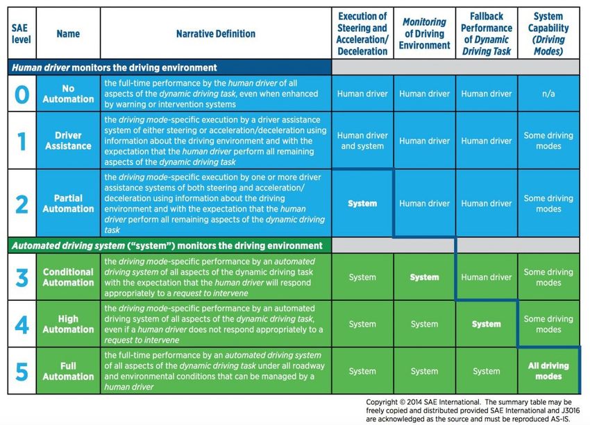
IEEE P2020 Automotive Imaging
         White Paper

                                                   Authored by
                                      Members of the IEEE P2020
                                                Working Group

                                                                  i
       Copyright © 2018 IEEE. All rights reserved.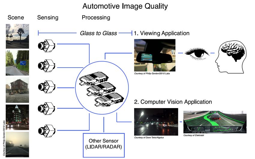
Trademarks and Disclaimers
IEEE believes the information in this publication is accurate as of its publication date; such
information is subject to change without notice. IEEE is not responsible for any inadvertent errors.

The Institute of Electrical and Electronics Engineers, Inc.
3 Park Avenue, New York, NY 10016‐5997, USA

Copyright © 2018 by The Institute of Electrical and Electronics Engineers, Inc.
All rights reserved. Published August 2018. Printed in the United States of America.

IEEE is a registered trademark in the U. S. Patent & Trademark Office, owned by The Institute of Electrical and Electronics
Engineers, Incorporated.

PDF: ISBN 978‐1‐5044‐5113‐0         STDVA23262

IEEE prohibits discrimination, harassment, and bullying. For more information, visit
http://www.ieee.org/web/aboutus/whatis/policies/p9‐26.html.

No part of this publication may be reproduced in any form, in an electronic retrieval system, or otherwise, without the prior
written permission of the publisher.

To order IEEE Press Publications, call 1‐800‐678‐IEEE.
Find IEEE standards and standards‐related product listings at: http://standards.ieee.org

                                                                                                                              ii
                                         Copyright © 2018 IEEE. All rights reserved.
Notice and Disclaimer of Liability
                                     Concerning the Use of IEEE‐SA Documents

This IEEE Standards Association (“IEEE‐SA”) publication (“Work”) is not a consensus standard document.
Specifically, this document is NOT AN IEEE STANDARD. Information contained in this Work has been created by, or
obtained from, sources believed to be reliable, and reviewed by members of the IEEE P2020 Working Group activity
that produced this Work. IEEE and the IEEE P2020 Working Group members expressly disclaim all warranties
(express, implied, and statutory) related to this Work, including, but not limited to, the warranties of:
merchantability; fitness for a particular purpose; non‐infringement; quality, accuracy, effectiveness, currency, or
completeness of the Work or content within the Work. In addition, IEEE and the IEEE P2020 Working Group
members disclaim any and all conditions relating to: results; and workmanlike effort. This IEEE P2020 Working
Group document is supplied “AS IS” and “WITH ALL FAULTS.”

Although the IEEE P2020 Working Group members who have created this Work believe that the information and
guidance given in this Work serve as an enhancement to users, all persons must rely upon their own skill and
judgment when making use of it. IN NO EVENT SHALL IEEE OR IEEE P2020 WORKING GROUP MEMBERS BE LIABLE
FOR ANY ERRORS OR OMISSIONS OR DIRECT, INDIRECT, INCIDENTAL, SPECIAL, EXEMPLARY, OR CONSEQUENTIAL
DAMAGES (INCLUDING, BUT NOT LIMITED TO: PROCUREMENT OF SUBSTITUTE GOODS OR SERVICES; LOSS OF USE,
DATA, OR PROFITS; OR BUSINESS INTERRUPTION) HOWEVER CAUSED AND ON ANY THEORY OF LIABILITY,
WHETHER IN CONTRACT, STRICT LIABILITY, OR TORT (INCLUDING NEGLIGENCE OR OTHERWISE) ARISING IN ANY
WAY OUT OF THE USE OF THIS WORK, EVEN IF ADVISED OF THE POSSIBILITY OF SUCH DAMAGE AND REGARDLESS
OF WHETHER SUCH DAMAGE WAS FORESEEABLE.

Further, information contained in this Work may be protected by intellectual property rights held by third parties or
organizations, and the use of this information may require the user to negotiate with any such rights holders in
order to legally acquire the rights to do so. IEEE and the IEEE P2020 Working Group members make no assurances
that the use of the material contained in this work is free from patent infringement. Essential Patent Claims may
exist for which no assurances have been made to the IEEE, whether by participants in this IEEE P2020 Working
Group activity or entities outside the activity. The IEEE is not responsible for identifying essential patent claims for
which a license may be required, for conducting inquiries into the legal validity or scope of patents claims, or
determining whether any licensing terms or conditions, if any, or any licensing agreements are reasonable or non‐
discriminatory. Users are expressly advised that determination of the validity of any patent rights, and the risk of
infringement of such rights, is entirely their own responsibility. No commitment to grant licenses under patent
rights on a reasonable or non‐discriminatory basis has been sought or received from any rights holder. The policies
and      procedures      under     which       this    document      was      created      can     be     viewed      at
http://standards.ieee.org/about/sasb/iccom/.

This Work is published with the understanding that IEEE and the IEEE P2020 Working Group members are supplying
information through this Work, not attempting to render engineering or other professional services. If such services
are required, the assistance of an appropriate professional should be sought. IEEE is not responsible for the
statements and opinions advanced in this Work.

                                                                                                                      iii
                                      Copyright © 2018 IEEE. All rights reserved.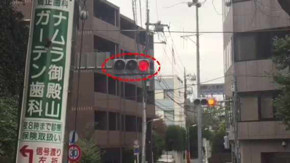
CONTENTS

ABSTRACT .................................................................................................................................................. 1

ACRONYMS AND ABBREVIATIONS .............................................................................................................. 1

1.       OVERVIEW ....................................................................................................................................... 2

A. GOALS OF THIS WHITE PAPER ................................................................................................................ 4

B. STRUCTURE OF THIS WHITE PAPER ......................................................................................................... 5

C. MOTIVATION FOR IEEE P2020 ................................................................................................................. 6

D. IEEE P2020 OVERVIEW AND LONG‐TERM OBJECTIVES............................................................................. 6

E. SUBGROUPS ........................................................................................................................................... 7

2.       PROBLEM STATEMENT ..................................................................................................................... 7

A. SUBGROUP 1—LED FLICKER STANDARDS................................................................................................ 7

B. SUBGROUP 2—IMAGE QUALITY FOR VIEWING ..................................................................................... 10

C. SUBGROUP 3—IMAGE QUALITY FOR COMPUTER VISION ...................................................................... 14

3.       GAP ANALYSIS ............................................................................................................................... 16

4.       REFERENCES .................................................................................................................................. 23

5.       AUTHORS (CONTRIBUTORS) ........................................................................................................... 24

                                                                                                                                                                iv
                                                    Copyright © 2018 IEEE. All rights reserved.
IEEE P2020 Automotive Imaging
                              White Paper
Abstract
The IEEE‐SA P2020 working group on automotive imaging standards was established in order to address the
considerable ambiguity in measurement of image quality of automotive imaging systems, both human and
computer vision based. This white paper outlines the goals, achievements, rationale and plans of the subgroup,
which has started to work on development of a new standard.1

Image quality plays a crucial role for both automotive viewing and automotive computer vision applications and
today’s image evaluation approaches do not necessarily meet the needs of such applications. Currently there is not
a consistent approach within the industry to measure automotive image quality. The IEEE P2020 working group is
attempting to remedy these deficiencies by connecting people in the field, identifying gaps in existing standards,
and working to address these by creating a coherent set of key performance indicators by which camera systems
and components may be evaluated in a manner consistent with their intended use. This white paper provides an
overview of current activities including initial gap analysis and details of what may be expected from the full
standard when published.

Acronyms and abbreviations
The following list of acronyms and abbreviations will be useful when reading this white paper:
ADAS                                          advanced driver assistance system
ADC                                           analog to digital converter
AEC                                           automatic exposure control
AI                                            artificial intelligence
AWB                                           automatic white balance
CaaS                                          car‐as‐a‐service
CDP                                           contrast detection probability
CFA                                           color filter array
CMS                                           camera monitor system
CPIQ                                          camera phone image quality (as used in IEEE Std 1858‐2016 [5])
CRA                                           chief ray angle
CSP                                           color separation probability
DR                                            dynamic range
ECU                                           electronic control unit

1
    For information on IEEE P2020, please visit http://sites.ieee.org/sagroups‐2020/

                                                                                                                1

                                                Copyright © 2018 IEEE. All rights reserved.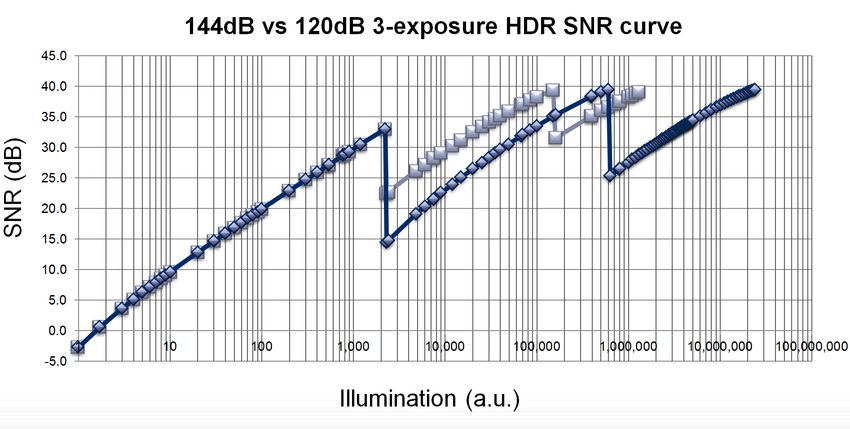
FoV                                 field of view/vision
FUN                                 Fidelity, Usefulness, and Naturalness
GDP                                 gross domestic product
HDR                                 high dynamic range
IQ                                  image quality
ISP                                 image signal processor
JND                                 just noticeable differences
KPI                                 key performance indicators
LTM                                 local tone mapping
MTF                                 Modulation Transfer Function
OECF                                Opto‐Electronic Conversion Function
PWM                                 pulse width modulation
QE                                  quantum efficiency
QoE                                 quality of experience
RVC                                 rear‐view camera
SAE                                 Society of Automotive Engineers
SNR                                 signal‐to‐noise ratio
SVS                                 surround‐view system
VGA                                 video graphics array (definition of a 640 x 480 resolution display)

Overview
Telephones were once for talking, and cars were once for driving. Things have changed. Mobile phones are now
ubiquitous digital assistants with cameras, sensors and extensive connectivity; while cars are on the verge of
becoming multi‐sensor, multi‐camera, multi‐modal autonomous artificial intelligence (AI) platforms. There are a
number of factors that drive this dramatic evolution of our vehicles—most notably, the ability to improve safety,
enable more efficient urban plans, and create new disruptive business models. The key driver for this dramatic
evolution in our vehicles is to increase safety.
The World Health Organization recently noted that more than 1.25 million people worldwide die each year as a
result of road traffic accidents and between 20 and 50 million more people suffer non‐fatal injuries, with many
incurring a disability due to their injury. This results in considerable economic losses to both individuals and their
families and to nations as a whole, which equates to approximately 3% of gross domestic product (GDP) for most
countries [1].
Advanced sensing will allow closer proximity inter‐vehicle travel distance than human‐controlled vehicles, reducing
the necessary lane width and freeing up space for wider sidewalks, bike lanes, and other amenities. As cities
transition away from ordinances that require large amounts of land to be used for parking and circulation, they will
need to determine how best to make use of that freed‐up space through new approaches of land use and zoning
(American Planning Association [2]). Furthermore, the transition to autonomous vehicles brings significant
opportunity in terms of new mobility business models (Gao et al. [3]). Car‐as‐a‐service (CaaS) also will provide car
mobility services for a large portion of the global population (Business Wire [4]), since no driver’s license is needed,
and it will prove to be an affordable transportation solution.

                                                                                                                      2

                                      Copyright © 2018 IEEE. All rights reserved.
While cameras are crucial for a vehicle to sense and perceive its surroundings, to date there has not been a
consistent approach in the automotive industry to measure image quality.
There is an existing standard for mobile phone camera image quality—IEEE Std 1858 [5]. This standard, however, is
generally not applicable to automotive requirements, and additionally other image quality standards, such as
EMVA1288 [6] or ISO 12233 [7], fall short for when it comes to automotive image quality use cases. Automotive
imaging imposes unique challenges due to its varied and distinct landscape of imaging conditions (fish eye, multi-
camera, high dynamic range (HDR), temperature range, etc.), which are not adequately addressed in existing
approaches. Therefore, the IEEE P2020 working group [8] has set the goal of shaping relevant metrics and key
performance indicators (KPIs) for automotive image quality, enabling customers and suppliers to efficiently define,
measure, and communicate image quality of their imaging systems.
Image quality (IQ) plays a crucial role for both viewing and computer vision applications. Figure 1 shows a generic
architecture of a multi-camera automotive system. In contrast to industrial machine vision systems, automotive
camera systems must deal with unconstrained environments, i.e., a wide range of weather, illumination, and
temperature conditions.

                          Figure 1 Architecture of multi-camera automotive system

For viewing-based camera systems (pathway 1 in Figure 1), the output image has to fulfill the pleasantness aspect
of image quality, which is related to the visual appeal of the image and is a key aspect of the quality of experience
(QoE) or level of satisfaction of the user. In such systems, however, the usefulness aspect of IQ, related to the
amount of useful information the visual image conveys (e.g., visible detail in shadow areas), is also vital. Balancing
pleasantness and usefulness is a challenge in the IQ tuning of viewing-based camera systems, since the two do not
always correlate.
For computer vision-based systems (pathway 2 in Figure 1), the individual products’ configuration of the hardware
components [lens, image sensor, image signal processor (ISP), etc.], their parameterization, as well as the
complete system IQ tuning, all have to prioritize usefulness. Here, it is important to note that biological vision and
computer systems do not necessarily interpret useful information in the same manner.

                                                                                                                    3

                                     Copyright © 2018 IEEE. All rights reserved.
Both viewing and computer vision camera systems are integral to many infotainment, driver assistance, and
automated driving functions. For some of these applications, images are the primary input for the human driver or
computer vision system to recognize and react to its environment. Therefore, it is extremely important that
meaningful KPIs are developed to quantify and describe the performance and limits of a camera system used in
such applications.
The Society of Automobile Engineers (SAE) has defined five levels of driver automation in SAE J3016 [9] with
increasing levels of driving function assigned to the system, see Figure 2. These automated vehicles will use suites
of sensors based on different technologies, of which camera systems are integral parts. As the automated driving
systems increasingly take more responsibility for human lives, it becomes urgent to develop standard metrics to
measure the performance and limits of image quality of these camera systems.
Figure 2 SAE autonomous driving levels as defined in the standard SAE J3016 [9]
A. Goals of this white paper
This white paper is the first publication of the IEEE P2020 Working Group on Automotive Imaging. A lesson learned
from the sibling group IEEE P1858 Camera Phone Image Quality (CPIQ) is that an ambitious standards development
effort in a rapidly changing technological field with so many different stakeholders can take many years to be
approved and published.
After our initial face-to-face meetings, it became clear that simply defining the relevant questions and listing the
open challenges would already be a useful achievement worth publishing. Typically, this information would be
published together with the actual IEEE P2020 standard, and would occur only after the new image quality metrics
4
Copyright © 2018 IEEE. All rights reserved.and new relevant KPIs have been defined, which may still take some time. Therefore, independent of the IEEE
P2020 standard publication stage, we decided to aim for intermediate publications to quickly communicate the
progress that the working group has made toward understanding automotive image quality. This white paper is
the first of these publications.
Consequently, the goals of this white paper are as follows:
1) Raise awareness that image quality for automotive application is not well-defined, critical metrics for
specification are missing, leading to repeated work efforts towards that matter. This white paper has two
sections that raise the awareness about missing image quality standards. Section 1-C gives the motivation
to start the IEEE P2020 effort in the first place. This includes information from the project authorization
request (PAR). Section 2 introduces several problem statements; each is a summary of findings by each
subgroup. In Section 3, a gap analysis of the existing image quality standards is provided. This is a list of
KPIs that are relevant for automotive image quality with a reference to existing standards, and also
provides an indication of the KPIs that do not have a standard (i.e., gaps in the standards landscape).
Further, the existing standards are often difficult or impossible to apply in automotive applications, or
they lack certain key features (e.g., in ISO 12233 [7], the evaluation of HDR is not covered). The presented
list contains commentary on what elements we consider missing or incomplete.
2) Raise awareness that the IEEE P2020 working group is trying to remedy these deficiencies to the best
extent as possible. It is time to develop a common language that customers and suppliers can use to
efficiently describe automotive image quality requirements. This publication attempts to raise awareness
that such an effort is under way.
3) Connect with other people already working on similar challenges. Because this field of technology is
advancing rapidly, and due to the enormous resources pouring into the development of new camera
systems for the automotive market, there are many people and organizations worldwide that are already
working on many individual aspects of automotive image quality. What applies to the goal of the standard
applies to the development of the standard itself—avoid duplicated efforts by connecting people working
in the field and raise synergies. This white paper points out the problematic state of automotive image
quality, and thus an important goal of this publication is to link together those who are already working
on solutions to fill the gaps.
4) Attract more people to help with the IEEE P2020 effort. This white paper is also a call to attract more
people and forge collaborations to help shape the future standards of automotive image quality.
B. Structure of this white paper
The rest of this section explains the motivation for the IEEE P2020 working group in more detail, the long-term
objectives of IEEE P2020 as well as the current structure of the working group with its different subgroups. The
actual content follows in the next two main sections:
A problem statement by each subgroup is given in Section 2.
A gap analysis is given in Section 3.
Section 2 describes the activity of each subgroup and formulates the challenges and missing standards in that area
into a problem statement. Currently, three of the later mentioned six subgroups are active and work to define new
quality metrics—subgroup 1: LED-Flicker, subgroup 2: IQ for viewing, and subgroup 3: IQ for computer vision.
The problem statements are generalized overviews of the main thrust of the work pursued by each subgroup. A
more detailed list of missing metrics and lacking standards is further given in the gap analysis in Section 3, where
Table 1 lists KPIs identified as important for automotive image quality. Where applicable, an existing standard is
5
Copyright © 2018 IEEE. All rights reserved.quoted. In some cases, the table already proposes new metrics to complement or replace existing KPIs. The gap
analysis list is a result of collaborative discussion by the working group before and during the preparation of this
white paper. We strongly hope that this list of existing standards and the indication of what is missing will be
extremely valuable for anyone working in the field of automotive image quality.
C. Motivation for IEEE P2020
The IEEE P2020 Working Group on automotive imaging was inaugurated at a plenary meeting prior to the
AutoSens 2016 Conference in Brussels, Belgium. The foundation of such a group arose from the needs of
stakeholders in the automotive imaging community after discussing relevant industry challenges.
Since the first automotive cameras were installed on vehicles, the Original Equipment Manufacturers (OEMs 1) and
the Tier 1 2 lacked a common language for describing the quality of images in a vehicle. The Tier 1 companies were
unable to exchange requirements with Tier 2 component suppliers that unambiguously reflected the aspirations of
the OEMs. There were standards developed for highly-restricted aspects of some components, but the industry
lacked empirically verifiable, repeatable, and commonly agreed upon descriptions for most salient aspects of the
image quality of a vision system in automotive.
In the absence of a clear description of image quality, the various stakeholders independently retreated into the
heuristic descriptions, to name one: “image quality is FUN” where FUN is an acronym for the Fidelity, Usefulness,
and Naturalness [10]. While providing a level of image quality semantics, this is an insufficient specification. The
ambiguity made projects more costly and tension in the projects more likely.
The ambiguity began with a lack of a basic description of image quality itself. While component-level descriptions
of performance criteria exist, their properties were neither monotonic indicators of image quality, nor did they
articulate image quality sufficiently. Examples of this include the MTF properties of lenses (using objective physical
units of cycles per mm) or the disparity of a recorded color value on a ColorChecker® chart 3 (using objective
physical units of Just Noticeable Differences in a color space).
After several engagements on a personal and professional level, largely facilitated by the AutoSens conference
environment, a group of automotive imaging professionals formed and organized themselves into the IEEE P2020
working group.
An overview on the state of IEEE P2020 was delivered at AutoSens 2017 in Detroit on 21 May 2017 as part of the
outreach work of the group in the industry [11].
D. IEEE P2020 overview and long-term objectives
The overview and long-term objectives of the IEEE P2020 standard are summarized as follows:
a) Scope: This standard addresses the fundamental attributes that contribute to image quality for
automotive advanced driver assistance systems (ADAS) applications, as well as identifying existing metrics
and other useful information relating to these attributes. It defines a standardized suite of objective and
subjective test methods for measuring automotive camera image quality attributes. Further, it specifies
tools and test methods to facilitate standards-based communication and comparison among OEM and
Tier 1 system integrators and component vendors regarding automotive image quality.
1
Original Equipment Manufacturers—the automobile companies.
2
A Tier 1 company is one that supplies components directly to the original equipment manufacturer (OEM) in the supply chain. A Tier n+1
company supplies a Tier n company in a supply chain.
3
ColorChecker is a registered trademark by X-Rite.
6
Copyright © 2018 IEEE. All rights reserved.b) Purpose: This standard specifies methods and metrics for measuring and testing automotive image quality
to ensure consistency and create cross-industry reference points.
c) Need for the project: Cameras are being used in greater numbers in automotive applications. Most of
these systems have been developed independently, with no standardized calibration or measurement of
image quality. Consumers have no standard reference point when using camera embedded systems, and
OEM or Tier 1 developers cannot compare camera systems side by side.
d) Stakeholders for the standard: Automotive OEMs, Automotive Tier 1 suppliers, image processing software
and hardware companies, optics companies, sensor manufacturers, safety certification bodies, end users
(drivers).
E. Subgroups
The various subgroups formed within the IEEE P2020 Working group are described below. An overview of the
projects is depicted in Figure 3.
Subgroup 0—Image quality requirements/specifications standards
Subgroup 1—LED flicker standards
Subgroup 2—Image quality for viewing
Subgroup 3—Image quality for computer vision
Subgroup 4—Camera subsystem interface
Subgroup 5—Image quality safety
Subgroup 6—Customer perception of image quality
Figure 3 IEEE-SA P2020 subgroups overview
2. Problem statement
This section describes the findings by the active Subgroups 1, 2, and 3.
A. Subgroup 1—LED flicker standards
1) Motivation: LED flicker is an artifact observed in digital imaging where a light source or a region of an imaged
scene appears to flicker. The light as observed on the vision system display may appear to switch on and off or
modulate in terms of brightness or color, even though the light source itself appears constant to a human
observer. An example of LED flicker is shown in Figure 4.
7
Copyright © 2018 IEEE. All rights reserved.Frame N Frame N+1
NOTE—The images above show two consecutive frames from a video sequence. In frame N, the traffic light in the front
(highlighted in red dashed circle) appears with red light on. However, in frame N+1, the traffic light in the front, which is still
visually observed by a human as a red light on, is no longer captured by the camera, thus leading all lights of the traffic light to
appear off.
Figure 4 Example of LED flicker 4
LED flicker is, in essence, a temporal/spatial sampling problem. It occurs when a light source is being powered by a
pulse width modulated (PWM) signal. LED lights may pulse several hundred times a second with varying duty cycle
(i.e. the fraction of one period when the light is active) in order to adjust their apparent brightness. At frequencies
greater than 90 Hz, the light will usually appear to be constant to most human observers. A camera capturing the
pulsed light source, however, may require a shorter exposure time than the temporal “ON ”period of the PWM
signal to prevent overexposure of the image, particularly in bright ambient light conditions. An illustrative example
of the timing phase mismatch that causes missing exposure is shown in Figure 5 [12].
2) Impact of LED Flicker: The implications of PWM flicker vary depending on the application. For simpler viewing
applications (e.g., a rear view park assist camera), LED flicker may be considered as an annoyance or at worst a
distraction for the driver. There is, however, a risk that LED flicker may trigger seizures in people with
photosensitive epilepsy. For a camera monitor system (CMS: a system that may optionally replace a conventional
vehicle mirror), flickering headlamps may be mistaken for turn signals and indicators or, as has been reported, may
cause the driver to misidentify a following vehicle as an emergency vehicle.
Flickering may also occur when a scene is predominantly illuminated by a pulsed light source. In this use case, a
large area or the entire image area may be affected. A typical example is a scene that is illuminated by a vehicle
headlamp or streetlight, which is driven by a pulsed signal. The flicker artifact has both temporal and spatial
characteristics. For example, if a rolling shutter image sensor is used, banding artifacts may occur, i.e., dark bands
across the image. An illustrative example of banding effect is shown in Figure 6. If global shutter read-out
architecture is used, the image brightness will vary from frame to frame.
4
Figures are modified from [12], reprinted with permission of IS&T: The Society for Imaging Science and Technology sole copyright owners of
Electronic Imaging, Autonomous Vehicles and Machine 2018.
8
Copyright © 2018 IEEE. All rights reserved.NOTE—In frame N, the LED pulse and the camera exposure time coincide, and the traffic light is captured. In frame N+1, the
LED pulse and exposure time do not coincide, and the traffic light appears off.
Figure 5 LED flicker root cause 5
NOTE—This image was captured with a rolling shutter image sensor. In this example, the scene is illuminated by a diffuse LED
light source, driven by a 75Hz, 10% duty cycle signal. The image shows a typical banding effect with darker horizontal stripes,
representing the rows missing the exposure of LED illumination ON timing.
Figure 6 Example of banding artifact5
5
Figure is a modified from [12], reprinted with permission of IS&T: The Society for Imaging Science and Technology sole copyright owners of
Electronic Imaging, Autonomous Vehicles and Machine 2018.
9
Copyright © 2018 IEEE. All rights reserved.For computer vision-based ADAS or autonomous driving applications, the consequences may be more severe. LED
flicker may cause misidentification of traffic signals, speed signs, or safety messages. It should also be noted that
LED flicker can adversely affect automatic exposure (AE) algorithms, causing oscillations in overall image
brightness. The goals of subgroup 1 are as follows:
Document the root cause and manifestations of flicker.
Capture use cases and potential impact of flicker.
Define standard test methodologies and KPIs for flicker effect measurement. Note that the KPIs and test
metrics are intended to be applicable for black box testing as system.
Correlate objective flicker metrics with subjective (visual) experience of flicker.
Correlate objective flicker metrics with computer vision performance.
B. Subgroup 2—Image quality for viewing
1) Motivation: Subgroup 2 on image quality for viewing will be engaged in developing meaningful KPIs to
characterize image quality for automotive cameras including rear-view cameras (RVC), camera monitor systems
(CMS), and surround view systems (SVS) and their components such as lens, color filter array (CFA), sensor, image
signal processors (ISP), and displays. The complete imaging chain (glass to glass, see Figure 1) is to be covered and
a preliminary approach is to measure the signal prior to the display, assuming a reference display and viewing
setup to be defined and applicable (display size, viewing distance, environmental illumination, etc.). A bottom up
approach is used to design metrics on the component level first and derive system performance as concatenation
of multiple components, thus benefiting from component level KPIs.
2) Problem statement: The image quality requirements for viewing application can hardly converge into a single
setup if different use cases are considered. Further needs to co-exist with the emerging computer vision
application make this problem even more difficult, imposing conflicting goals.
For example, even within purely viewing-based systems, the users will judge the image by two contradicting
judgements: By its usefulness (e.g., displayed details) as well as visual aesthetics (e.g., less noise). Different image
quality aspects contribute to a pleasing image but may conflict with one another, e.g., noise vs. brightness vs.
sharpness vs. texture vs. color saturation. Figure 7 shows an example of how an image could look according to
different capture settings and/or processing.
In the context of automotive imaging, image quality KPIs for viewing need to be able to meet these competing
aims simultaneously. This is challenging and it may largely depend on the task performed by a driver viewing the
images provided by the camera visual system.
Automotive IQ KPIs need to reflect such conflicting goals of the images’ use.
10
Copyright © 2018 IEEE. All rights reserved.(a) (b)
(c) (d)
NOTE—Images (a) and (b) demonstrate an example of trade-offs between image usefulness and visual aesthetics. Both are
night images of the same scene that were captured using two compatible camera modules in HDR mode but with different
operation settings. While one may observe more details and, therefore, be able to better distinguish between the objects in
image (a), image (b) taken with different settings provides a more pleasant image thanks to lower noise levels and a higher
contrast between bright and dark objects. For comparative purposes, images (c) and (d) show a crop of the central region of
images (a) and (b) respectively.
Figure 7 Tradeoff example
There are a number of major challenges to incorporate current image quality standards in an automotive
environment, such as the following:
Fish eye lens, focus, resolution—The use of fish eye lenses with wide angular field of view and fixed
focus, combined with relative low resolution image sensors imposes specific challenges. In these scenarios,
typical test chart sizes and setups are too small, resulting in images without a sufficient number of pixels
for robust analysis. Decreasing the distance between test chart and camera introduces new problems. On
the one hand, if the chart is positioned at a distance to cover the entire image area, that distance may
become shorter than the camera designed depth of field and result in a blurred image. On the other hand,
fish eye lenses usually suffer from lens distortion. This introduces other problems (failure of the charts’
patch automated detection with existing tools, distorted patch sizes at different locations within the
image, etc.). Simply increasing the test chart size will not solve the problem and introduces other
challenges, e.g., achieving a uniform illumination over the entire charts area that are often required for
most image quality standard evaluation procedures.
11
Copyright © 2018 IEEE. All rights reserved. HDR—High dynamic range imagers are often combined with local tone mapping image processing. This
creates challenges of texture and local contrast preservation, color fidelity/stability, SNR stability (see
Figure 8), and motion artefacts.
Multi-cam—In applications such as SVS, image capture originating from multiple cameras with
overlapping field of views are combined or “stitched” together. The created virtual image evaluation is
problematic due to the individual characteristics of each camera and captured portion of the scene, i.e.,
different fields of view, local processing, different and mixed camera illumination.
Distributed—Distributed systems with some local image processing close to the imager and some ECU
centralized processing. Local processing (e.g., tone mapping) does not preserve the original information at
the camera and is therefore not invertible to be post recovered in the central ECU (e.g., glossy
compression/quantization).
Dual purpose—The same camera feed may have to serve both for viewing and computer vision needs.
Extrinsic components—System level image quality is affected by additional components of the vehicle
(lights, windshield, protection cover window, etc.).
Video—Automotive systems use video imagery. Many of current imaging standards, however, were
originally targeted for still image application and typically do not cover motion video image quality.
Illumination—The huge variety of the scene illumination in automotive use cases imposes additional
challenges for testing (e.g., xenon light, d65 light, sunlight, various LED street lamps).
Another issue is that the existing standards do not necessarily cover the specific challenges that occur in
uncontrolled use environments, in which automotive camera applications need to operate.
Figure 8 shows a typical SNR versus illumination curve of camera using a multi-exposure type of HDR operation.
When a high dynamic range scene (e.g., tunnel entrance/exit) is captured, a counterintuitive phenomenon may
occur in regions of the image above the intermediate SNR drop point. Brighter regions above those drops will
exhibit higher noise than regions with a lower brightness. This means that there is more noise in the intermediate
bright regions than in the dark ones. In the case where an application requires a certain minimum level of SNR,
these intermediate drops become an issue because existing standards on HDR do not consider such intermediate
SNR drops. Figure 8 illustrates an example SNR curve of a sensor operated in an optimized configuration to achieve
improved SNR at these drop points. This consequently leads to reduced dynamic range from 144 dB down to
120 dB, according to operation adjustment required to achieve an improved overall SNR level.
Figure 8 SNR vs. illumination for multi exposure HDR imagers
12
Copyright © 2018 IEEE. All rights reserved.SNR spatial drop within an image may also be observed in camera using wide angular field of view fish eye lenses.
Typically, cameras with a wide FoV lens have a high degree of lens shading, which means the signal drops radially,
in some case to a level lower than 50%. If we consider a SVS where typically four different wide field of view
camera images are processed to generate a virtual bird’s eye view image from above a vehicle, brightness
correction is performed to compensate for the darker peripheral image (as in image shown in Figure 9). The lens
shading correction is applied to mitigate the bordering effect of the image coming from different cameras, which in
turn leads to an inhomogeneity in the SNR as higher gain is applied to the peripheral area of the fish eye lens. This
non-uniform, spatially varying effect gets extremely prominent, especially for a multi-camera combined SVS. The
higher the gain to compensate for the lens shading at the peripheral area of the images causes the borders of the
stitching areas to generate a large step of visible noise, in some case to a perceivable level when observing these
images.
NOTE—The left side image is a combination of a left, front, right, and rear mounted camera image to create a virtual top view
image in a SVS image. The right side image is native image of rear camera to provide view corresponding to a RVC image. All
images from cameras are capturing a near uniformly illuminated white flat chart. In the right side, one can observe a signal drop
toward the periphery, and the left side, one can observe steps in the signal along the merging stitching lines along of
neighboring camera in a SVS view.
Figure 9 Brightness inhomogeneity due to lens shading in a combined multi-camera view
Typically, in the existing IQ standards, one major requirement prior to the calculation of a metric is the
linearization of output values. This involves the calculation of the Opto-Electronic Conversion Function (OECF) and
correction of any system non-linearity accordingly. The typical automotive camera system with HDR and Local
Tone Mapping is a nonlinear system. The linearization of the input signal under strictly controlled parameters is
still possible, but in a typical automotive application use case, e.g., in scenes with high dynamic range, the same
conventional linearization procedure cannot be used anymore. As many KPI are calculated assuming a linear
relationship of the output signal, the unavailability of OECF has a significant impact on the calculation of several
conventional IQ standards such as sharpness, noise texture, etc.
Furthermore, due to the high dynamic range of the imager, technical challenges arise for the optical design of the
lenses. Repeated reflections of the light inside the lens will lead to ghost images such as the headlights of a car. As
we use a HDR sensor combined with LTM (local tone mapping), the ghost image of the headlights will be amplified
to a significant level at dark region of the same captured image. For CMS camera systems, this will lead to two to
three pairs of headlights in the actual image, which can be misguiding for the driver. Unfortunately, the higher the
imager DR and LTM performance, the more serious these ghosting problems will become.
13
Copyright © 2018 IEEE. All rights reserved.A number of challenges arise when using the texture measurement metric in automotive applications (used by
CPIQ), which is based on the dead leaves test chart. Again, the wide FoV and low resolution will not provide
enough pixel counts for a robust and reliable measurement. Decreasing the distance or increasing the target size
will distort the well-defined frequency distribution and geometrical invariances of the dead leaves within the test
chart due to the high lens distortion. Typically, low texture KPI values are caused by high noise reduction filtering in
the image. However, if we now have an image where the SNR is not a continuous function of the illumination due
to the SNR drops, and the noise reduction filtering is hence not necessarily done equally over the whole image,
then we have to ask: How much can we benefit from the measuring method as presently described in the CPIQ
standard?
Given the multitude of use cases and complexity to achieve good KPIs, subgroup 2 has decided to first work on
development of the following ease implementation ones, in a bottom up approach, before further moving to
complex KPIs:
Dynamic range
Sensitivity
Depth of field
Focus stability
Dark current
Our ultimate goal is to design KPIs to characterize image quality with regard to both the pleasantness and
usefulness to the automotive viewing camera systems; and will further tackle new KPIs at next stage.
C. Subgroup 3—Image quality for computer vision
1) Motivation: Video-based environment recognition is expected to be one of the major components of an
advanced driver assist system (ADAS) or automated driving system. The process of environmental visual data
acquisition is the result of a complex effect chain, also called imaging chain, which starts from a light source and
ends with the final image stored in memory. In this information transfer chain, the signal suffers from a variety of
intermediate disturbances, thus degradation of the signal quality will always take place to some extent. It is
important that the system is designed so that enough relevant information about the world is still preserved in the
chain. Hence, it is evident that meaningful KPIs need to be defined. Because the tasks of computer vision are so
diverse and are solved in many and constantly evolving ways, existing standards such as EMVA 1288 [6], are
typically restricted to component-level characterization. However, to cover special automotive use cases, the
complete system along the imaging chain has to be considered. Existing international standards for image quality,
while application based, almost exclusively focus on the case of digital imaging for human consumption. The
machine vision use cases of automotive imaging are so diverse, and the penalty for failure so severe in critical
cases, that existing standards are inadequate for computer vision automotive application. What might lead to
merely acceptable image quality degradation for human consumption may lead to sudden unacceptable failure for
a computer vision system.
As an example, consider the scenario illustrated in Figure 10, wherein a vehicle passes from being in direct sunlight
into a tunnel. The vehicle has a dirty windshield and the forward-facing camera is essentially blinded by veiling
glare introduced at the surface by haze and/or reflections. Thus, the distinguishability of the scene feature (i.e., the
car) is vastly reduced. The car becomes clearly visible once the vehicle windshield enters the tunnel and the veiling
glare is not present anymore. A situation such as dirt on the windscreen will drastically reduce the detection
probability of the relevant object (e.g., a car), regardless of the specifics of the system analyzing the video feed.
Intelligent driving systems that make use of these video feeds and other sensors modalities are not allowed to fail
in such cases. Therefore, it is vital to provide these systems with all the necessary information from the
environment in order to make proper decisions.
14
Copyright © 2018 IEEE. All rights reserved.NOTE—Two sequential video frames while entering a tunnel that demonstrate contrast reduction by veiling glare, caused by
sunlight illuminated dust particles. In the left image, the effect significantly hinders the recognition of a preceding car while in
the right image (only a few milliseconds later) the sunlight is blocked away and a robust detection of the car is possible.
Figure 10 Two sequential video frames while entering a tunnel that demonstrate contrast reduction by veiling glare 6
2) Problem statement: Traditionally, the evaluation and characterization of components in the imaging chain were
covered by specific expertise in the field of each component. For example, optics KPIs such as Modulation Transfer
Function (MTF) and such as the quantization of various effects of scattered light in the optical system are not
directly compatible with image sensor KPIs like signal-to-noise (SNR) and dynamic range (DR). The overlapping
effects between components often do not have a common unified evaluation standard across the component
chain. Following the example in Figure 10, a standard approach might have been to quantify how much veiling
glare a dirty windshield adds to such an imaging situation, and for the vision system designers to account for this in
their design, whatever the application might be.
Thus, the definition of the components requirements for an ADAS system is a complex procedure. A particular
effect observed in the intermediate data flow is not necessarily isolated and it requires a complex analysis of the
complete information transfer flow. This means it is necessary to analyze the chain from optical level down to
electronic signal level (see Figure 11), and this must be done considering the use cases in which the system is
expected to operate. Therefore, it is essential that components are not just characterized as isolated elements but
rather all effects in the chain are well covered under a single framework so that the total system can be
appropriately characterized.
Given the example of Figure 10, the reduced contrast after the windshield could still be detected by an image
sensor with sufficient contrast detection ability and consequently the ISP may reconstruct an image that allows
detecting the car even in the left hand side image with a still sufficient detection probability.
6
Figure from [13] reprinted with permission of IS&T: The Society for Imaging Science and Technology sole copyright owners of Electronic
Imaging, Autonomous Vehicles and Machine 2018.
15
Copyright © 2018 IEEE. All rights reserved.Figure 11 Example flow diagram of an imaging chain6
In order to design robust systems for the automotive industry, IEEE P2020 subgroup 3 (Image Quality for Computer
Vision on System and Component Level) aims to develop consistent metrics that both describe various
degradations and give bounds on their confidence. We will explore the probabilistic approach of distinguishability,
such as the contrast detection probability (CDP). This helps to visualize the overall signal chain and aims to improve
the cross domain barrier. CDP is a metric designed to specifically measure this fundamental aspect, using a
framework well founded in theory (Geese et al. [13]). Moreover, CDP has the ability to be applied to each element
of the imaging system chain, so that the original task can be described at each step in the imaging chain.
3) Outlook and Conclusion: Within the discussions, subgroup 3 gave awareness for new top-level image quality KPIs
for automotive computer vision applications. In a first approach, these new top-level KPIs will be based on the
principle of detection probabilities. As the first of these new probabilistic KPIs, the Contrast Detection Probability
[13] is already defined in the scientific community; IEEE P2020 will adapt this definition into a first proposal by the
end of 2018. Here, a validation of this CDP approach with exemplary cameras will be demonstrated in laboratory
test environments by members of the working group. For the distinguishability of traffic-relevant colors, the
discussion of a probabilistic approach has already begun in analogy to the principles of CDP and is referred to as
color separation probability (CSP). A further important domain of image quality is the geometric resolution that
will follow with high priority. For all definitions and KPIs, subgroup 3 plans to contribute an example
implementation to verify and develop the newly defined KPIs against the currently established KPIs, while a
laboratory validation is intended to follow as described above.
3. Gap analysis
Because automotive imaging is quite unique with regards to hardware setup and customer functions, it became
clear that existing image quality KPI standards are not sufficient to address such systems. Table 1 exemplarily
depicts some obvious gaps. The goal is to identify the attributes within the relevant environmental conditions that
affect the image quality of automotive systems and subsequently define universal methods to quantify them.
16
Copyright © 2018 IEEE. All rights reserved.Table 1 Gap analysis
Technical Existing Original use case of Correlated Item,
Item industry existing standard, or Gap to automotive particular needs Cat.
category standards comments comments
Dynamic range ISO 15739: Evaluation on Dynamic range definition on multi-exposure type of sensor; Window glare, Sensor
2017 [14], monotonical response dynamic range of displayed imaged with adaptive tone optics flare, sensor
EMVA 1288 input image. Given as mapping; dynamic range considering a minimum SNR intrinsic dynamic
[6] the ratio of the signal required over its defined range. (A minimum SNR required to range and
saturation to the perform intended operation, e.g., distinguishing an object.) quantization,
absolute sensitivity compression I/F
threshold
Contrast New — Gap to close: Define the dynamic range and other — System
Detection approach in dependencies, where the signal allows the detection of a and
Probability IEEE P2020 certain Object Category (feature: Contrast) for the targeted Compon
(Dynamic range application. For more details, see literature [13]. For ent Level
that meets example, guarantee detection even if SNR drops are present
specific CDP) in multi-capture systems.
Sensitivity ISO 12232 Digital Still Camera, Definition extend to IR spectrum. — Sensor
[7], Visual spectrum
Speed; EMVA
1288 [6], QE
Tonal
Low light ISO 19093 Smartphone camera Low light performance on actual use condition, definition SNR, Temperature Sensor
response performance [15] (in evaluation is main considering trade-off operation according to application (2D, dependency, NR
development) focus of this standard 3D NR operation dependence on scene brightness, ...). operation
SNR 1/5/10 — Illuminance in lux that Alternative to low light performance. — Sensor
delivers image with at
least the defined SNR
value equal to 1, 5, or
10 for a neutral grey
patch.
Tonal shading ISO 17957 Metrics defined using Needs adaptation to wide view angle application. Optical, CRA Sensor
[16] a flat target chart
Chroma shading ISO 17957 Metrics defined using Needs adaptation to wide view angle application. Optical, opto- Sensor
[16] a flat target chart device, device
cross-talk
OECF ISO 14524 OECF (Evaluation on Evaluation on adaptive tone mapping operation. — Sensor
[17] monotonical response
input image)
17
Copyright © 2018 IEEE. All rights reserved.Technical Existing Original use case of Correlated Item,
Item industry existing standard, or Gap to automotive particular needs Cat.
category standards comments comments
Resolution ISO 12233: Units given relative to Definition required according to intended use FoV; — Optics
2017 [7] image full Metric to evaluate scene distinguishability performance;
dimension/optical Partial/converted image resolution from a fish eye lens.
definition (Example: CMS where output image evaluation is based on
displayed image instead of camera intermediate image).
Limit resolution (can be Defined according to For automotive visual application, object in the range of — Optics
derived from required use case interest must be distinguishable. The spatial frequency
ISO 12233: where MTF drops to 10%, or MTF10, is adopted for
2017 [7]) automotive visual application as representative
characterization value, e.g., CMS applications.
Sharpness (can be — The peripheral vision plays an important role in the first — Optics
derived from stage of visual detectability of object and it is known that the
ISO 12233: edge contrast stimulates the peripheral vision. The spatial
2017 [7]) frequency where MTF drops to 50%, or MTF50, is adopted
for automotive visual application as representative
Spatial characterization value.
response Depth of field — — There are industry practices to measure depth of field/focus, — Optics
but no standard exists based on object distance and MTF
requirements. In principal, one may expect a camera to be
assembled in hyper-focal distance with good focus achieved
in a range from half of the hyper-focal range to infinity, if
otherwise not mentioned.
Texture ISO 19567-1 Low distortion image Optics
[18], to maintain chart
ISO 19567-2 spatial frequency
[19] characteristics
Motion Blur No existing This item is more an intrinsic effect due to the exposure time Sensitivity, various
(Single exposure standard used to capture a frame image. Electronic Shutter
tail, Multi operation
exposure Ghost in
HDR single frame)
Temporal Flicker (observed No standard (Temporal to spatial Need to cover the emerging use of LED light source, which — Sensor
response undulation effect) for camera transformation due to nowadays largely used in many road environments
(Focal Plane Shut- operation, time-sequential (including reflected scene illuminated by such type of
18
Copyright © 2018 IEEE. All rights reserved.Technical Existing Original use case of Correlated Item,
Item industry existing standard, or Gap to automotive particular needs Cat.
category standards comments comments
ter) at low to Standard sampling characteristic source) Intra/Inter-frame static, semi-static, moving
middle range defined only of the focal plane undulation.
scene luminance for light shutter sensor
source operation)
Flicker (observed No standard (HDR operation used Need to cover the emerging use of LED light source in road Localized (point) Sensor
flickering effect) for camera to cover for the environment (traffic sign, headlamp, tail lamp, traffic signs, light source
(FPS & HDR operation, highlight are affected etc.)
w/Local Tone but as light by the adaptive tone
Mapping: LTM) source mapping and/or
further time
sequential multi
sampling , and its
multi-frame merging
signal process,
creating non-linear
artefacts)
Flicker (Global No standard Need to cover the emerging LED light source used in road — Sensor
Shutter) for camera environments, parking, etc.
operation,
but as light
source
Spectral Quantum EMVA 1288 — — — Sensor
Efficiency [6]
Color Rendering — — Automotive scene may contain scene illuminated under a — Variable
variety of different light source. Also light source captured as
part of the scene may largely differ from the scene
illumination. Compared to post adjustable use case of
Spectral photographic application like DSC or post processed video
response application, a precise color rendering is not expected to be
achievable.
Distinguishability — — Although a precise color rendering is not applicable or Distinguishability Various
of traffic relevant feasible, the extent of color deviation shall be such that of traffic relevant
color traffic relevant colors are still distinguishable within same light source colors
color classification range. Red as red, green as green, amber
as amber.
19
Copyright © 2018 IEEE. All rights reserved.Technical Existing Original use case of Correlated Item,
Item industry existing standard, or Gap to automotive particular needs Cat.
category standards comments comments
Lens flare ISO 18844 — In automotive use environment, headlamps direct light Distinguishability Optics
[20], IEC and/or direct sun light often enters the FoV or hit the optics of target objects
62676-5 [21] of the camera system. Stray light of incident light onto affect by flare
optical system shall be evaluated in term of veiling effect
that deteriorate image visual or post processing
performance.
Ghost — Secondary image of — Optics
primary light source
created by stray light
reflected within the
optical components
Veiling glare ISO 9358 [22] Stray light that — Lens flare, Optics
Optical reduces the image or distinguishability
artifact display contrast over a of objects affected
significant area of the by flare
total image or display
area
Lens color ISO 19084 — — — Optics
aberration [23]
Stray light — Stray light is a general — — Optics
term that refers to
light affecting the
image quality that is
unintended by the
optical system.
SNR ISO — Noise reduction operation is largely adopted in camera — Sensor
15739:2013 systems, but may result in spatial resolution degradation.
[14] Therefore, for the comparative evaluation of system,
measuring operation condition shall be defined in
accordance. HDR operation suffers the degradation of SNR in
Noise intermediate brightness rather than at low light condition.
Read-out noise EMVA 1288 — — Sensor
[6]
Temporal noise ISO 15739: Temporal Read Noise — — Sensor
2013 [14], is the time-dependent
20
Copyright © 2018 IEEE. All rights reserved.You can also read