Imaging the vascular network of the human spleen from immunostained serial sections
←
→
Page content transcription
If your browser does not render page correctly, please read the page content below
Eurographics Workshop on Visual Computing for Biology and Medicine (2014)
I. Viola, K. Bühler, and T. Ropinski (Editors)
Imaging the vascular network of the human spleen from
immunostained serial sections
Christine Ulrich1 , Oleg Lobachev2 , Birte Steiniger3 , and Michael Guthe2
1 Technical Workshop, Psychology Faculty, Philipps-University Marburg, Germany
2 Visual Computing, University Bayreuth, Germany
3 Institute for Anatomy and Cell Biology, Medical Faculty, Philipps-University Marburg, Germany
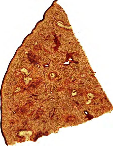
Figure 1: From left to right: One slide of an immunostained specimen of the human spleen stained for CD34 occurring endothelial
cells of capillaries and larger blood vessels and in a small fibroblast population; the scan resolution is 25856 × 32000. Detail
of the slide showing the stained capillaries. Detail of the iso-surface reconstruction from the aligned serial sections. Volume
rendering of a further spleen immunostained for CD34, smooth muscle alpha actin and CD271 (first two targets colored brown,
the latter one colored blue), both aligned with our technique.
Abstract
The spleen is one of the organs, where the micro-structure and the function on that level are not completely
understood. It was for example only recently found that is has an open circulation, which distinguishes it from all
other organs. Imaging the complete vascular network from the arteries to open-ended capillaries would greatly
facilitate research in this area.
The structure of such tissue is best uncovered using immunehistological staining. This can however only be applied
to thin tissue sections and larger structures span several slices. Due to the deformation induced when cutting the
specimen, standard registration algorithms cannot be used to merge the images into a volume.
We propose a specialized matching algorithm to robustly determine corresponding regions in the images. After
a rigid alignment of the scans, we use a cubic B-spline to deform and align the images. During this process we
minimize the total deformation to produce as accurate results as possible.
Categories and Subject Descriptors (according to ACM CCS): I.4.3 [Image Processing and Computer Vision]:
Enhancement—Registration
1. Introduction the other hand, small structures of less than 1 µm are also im-
portant to understand the structure and function of the tissue.
Imaging blood vessels, nerves or other mesoscopic structures
Therefore, only microscopy based approaches are applicable
has several applications in biology and anatomy. Such struc-
in this context.
tures may span regions of one or several millimeters and
specimen of such size need to be digitized as a whole. On Our methods aim at providing insights into the course of
c The Eurographics Association 2014.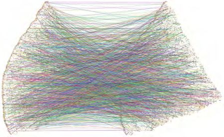
Ch. Ulrich et al. / Imaging the vascular network of the human spleen

arterial blood vessels in the human spleen. The spleenic vas-           activity is blocked. We first use a specific antibody, which
cular network is open: the capillaries have open ends and               binds to the surface and/or the interior of the cut cell. Then
no connections to the venous sinuses. Thus, the blood flows             a second antibody binding to the first one is subsequently
through the connective tissue without any separating wall               applied. This secondary antibody has been conjugated to the
and – interestingly – without clotting. This behavior is be-            small molecule biotin. Biotin is used, because it is bound by
lieved to be unique to the spleen, signifying the importance            the protein avidin at one of the highest affinities known in
of the study of its blood vessel system. In addition, the human         biological systems. To detect the biotin-labeled secondary
spleen has specialized capillary vessels (called sheathed cap-          antibody, we using a molecular complex of avidin and biotiny-
illaries), which do not occur in any other organ. The location,         lated peroxidase containing many unoccupied biotin-binding
shape and function of these vessels need to be clarified. Our           sites in the avidin molecules.
goal is to enable answers to these questions by depicting the
                                                                           When the molecular complex is applied to the sections, it
shape of the vessels in an aligned stack of serial sections.
                                                                        binds to the biotin of the secondary antibodies. This means,
Registered serial sections are then used to obtain volume or
                                                                        that many peroxidase molecules are present at the site of
mesh data of the capillary network. It does not make sense to
                                                                        the antigen. Peroxidase is an enzyme which catalyzes an
regard a single slide, as it is too thin to contain blood vessels
                                                                        oxidative polymerization of soluble color substances such as
connected at a mesoscopic dimension.
                                                                        diaminobenzidine to an insoluble product in the presence of
   Injections or genetic modifications, which are commonly              hydrogen peroxide. Thus, a permanent brown precipitate is
used in biological models, are not possible in humans. As a             deposited, where the enzyme has exerted its function at the
consequence, staining of specific cells to discriminate them,           location of the first antibody.
has to be performed after removal of the specimen. The only
                                                                           After sealing the stained section it with a cover slip, the
applicable technique that is versatile enough, is immuno-
                                                                        slide can be scanned for further digital processing. Figure 1,
histological staining. Unfortunately, staining substances do
                                                                        left, shows a detail of a scanned immunostained specimen
not penetrate a specimen further than a few micrometers.
                                                                        using diaminobenzidine (brown) only. This staining desig-
Despite recent advances in confocal microscopy, it is there-
                                                                        nates capillary endothelial cells, blood stem cells, and certain
fore not possible to examine specimens with a thickness of
                                                                        fibroblasts in the spleen. We use it to visualize the vascular
more than approximately 50 µm using immunostaining. The
                                                                        network. Some specimen (like Figure 1, right) are also im-
only technique left is preparing 5–10 µm thick serial sections.
                                                                        munostained for further targets, shown in brown and blue
This allows immunohistological staining, but disassembles
                                                                        color. In our experiments, we utilize CD34 immunostaining
the overall structure in mesoscopic dimension and produces
                                                                        as a standard.
deformations. As a result aligning the sections and recon-
structing the volume is needed. Series with up to 400 sections             We used a Leica SCN 400 slide scanner with an opti-
are possible, amounting to a total thickness of up to 4 mm.             cal magnification factor of 20. With this magnification, the
Smaller series with up to 50 sections are simpler to produce            scanner produces images with a spatial resolution of about
and we thus currently work with this range. Our techniques              0.33 × 0.33 µm per pixel. The section thickness is approxi-
are however applicable to these larger series as well.                  mately 7 µm.
   So far only small details of serial sections have been used to
examine blood vessels or nerves. With the recent introduction           1.2. Aligning Serial Sections
of automated slide scanning microscopes, large serial sections          After scanning the immunostained serial section, the images
can be digitized with high resolution. However, the special             have to be aligned to assemble them back into a volume. This
properties of serial sections pose several challenges for such          alignment process however poses several challenges.
a reconstruction, which we will discuss in the following.
                                                                        • The sections are significantly deformed by the cutting
                                                                          knife of the microtome. While small deformations are
1.1. Immunohistological Staining                                          tolerable for a single section, they need to be corrected for
                                                                          a 3D reconstruction. This means that some non-linear local
Immunohistological staining is a procedure to detect proteins
                                                                          deformations have to be applied to the scanned slides.
or other antigens in thin sections of tissue that have been
                                                                        • Removing the embedding material has the consequence
either fixed and embedded in paraffin or a similar material for
                                                                          that no external markers can be used for the alignment.
cutting with a microtome. Alternatively, frozen sections may
                                                                          In contrast to many other applications, it is therefore not
be used. There are different detection systems available. The
                                                                          possible to use registration markers since they would be
system used for our experiments is called the “ABC”-system
                                                                          lost during staining.
(avidin-biotinylated peroxidase complex system).
                                                                        • The specimen is human or animal tissue scanned at a high
   For processing of the sections the embedding material                  resolution. Therefore, the images contain highly repetitive
needs to be removed in a first step. Then appropriate antigen             structures – i. e. cells – and pose high demands on the
retrieval is performed and endogenous biotin and peroxidase               processing algorithms. Among other things, this implies

                                                                                                           c The Eurographics Association 2014.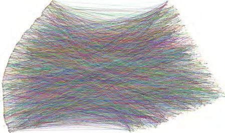
Ch. Ulrich et al. / Imaging the vascular network of the human spleen

  that gradient domain, block- and feature matching cannot                  MRT data sets. Ma et al. [MLW∗ 08] developed a method
  be used directly.                                                         to align sections of a mouse lymph node. It is based on
                                                                            first globally aligning a binary image generated by a fore-
   The main contribution of the paper is a novel, feature based
                                                                            ground/background segmentation. Then a multi-resolution
registration and alignment algorithm that was specifically de-
                                                                            algorithm is used to refine the rigid alignment. A similar ap-
signed for immunostained serial sections of tissue. It solves
                                                                            proach was proposed by Tanacs and Kato [TK11] for MRT
several problems that render classical image registration tech-
                                                                            images. Ju et al. [JWC∗ 06] utilize the continuity of the bio-
niques unsuitable in the context of serial section alignment. It
                                                                            logical matter to reduce “jitter” in the registration of a slide
is robust to highly repetitive smaller structures that otherwise
                                                                            series with warp filtering.
lead to erroneous alignments. Using an iterative re-matching
of the features, it is able to find correct correspondences for a              As Steiniger et al. already noted: “Slight distortions of the
large number of features and automatically removes outliers.                single sections during the cutting process (and other reasons)
It minimizes the overall deformation of the specimen since                  led to an irregular outline of the vessels” [SRB03]. Rigid-only
we do not align to a single reference slice. Thus it reduces the            registration was studied in context of MRI and similar kinds
influence of the cutting-induced distortions in the individual              of data [RPMA01, JS01, MBNV04].
slices.

                                                                            2.2. Non-rigid Registration
2. Related Work
                                                                            Cifor et al. [CBP11] register 2D histological scans using the
Shams et al. [SSKH10] provide an extensive survey of paral-                 smoothness assumption: the surface-to-reconstruct is a bio-
lelized algorithms for medical image registration. The meth-                logical artifact that should not have non-continuous jumps.
ods they discuss are however all based on local difference                  The elastic method is a quite popular approach [GBB∗ 01,
measures and thus not directly suitable for our problem. Sim-               CBR∗ 11]. Gefen et al. [GTN03] use a 3D wavelet to
ilarly, Hill et al. [HBHH01] compared various approaches to                 elastically transform histological images. Bajcsy and Ko-
register MRI and PET images with CT data.                                   vačič [BK89] developed a multi-resolution elastic algorithm
   There are also several books on medical image regis-                     to register CT data sets. Saalfeld et al. [SFCT12] use a 2D
tration algorithms. Goshtasby [Gos05] gives a very broad                    elastic triangulation of Hookean springs for block matching.
overview of the methodology and applications of differ-                     Wirtz et al. [WPFS05] use higher-order image derivatives.
ent techniques. More detailed descriptions of various ap-                   Thirion [Thi98] used a diffusion model based on thermody-
proaches and a deeper mathematical background are provided                  namic concepts to register two images. Bagci et al. [BCU12]
by [SWL05, Sch06, HH10]. All of these books explicitly dis-                 review the modern state of the art approach based on multi-
cuss non-rigid registration methods in the context of clinical              resolution methods. All multi-resolution methods however
imaging, i. e. CT, MRI, and PET data. An overview of bio-                   require data containing large structures which are not present
imaging software tools is given by Eliceiri et al. [EBG∗ 12].               in our specimen.
                                                                               Rueckert et al. [RSH∗ 99] developed a non-rigid registra-
2.1. Registration of Serial Sections                                        tion of 3D models, especially breast MRTs. It is similar to
                                                                            our work as it also uses a B-spline based deformation. The
Only few methods to align serial sections of tissue exist.
                                                                            matching is however based on the mutual information of the
Among these are manual alignment techniques [vKTVHW85,
                                                                            images [WVA∗ 96, PLD05] and thus requires clear edges and
SRB03]. This approach was later improved by Steiniger et
                                                                            larger uniform areas in the images. This approach was fur-
al. [SBS11] using a joystick as input device.
                                                                            ther improved to utilize multi-level B-splines [SRQ∗ 01]. This
   One of the first practical approaches was the ICP algo-                  allows simulating a non-uniform control point grid, but the
rithm [BM92]. Several semi-automatic approaches for the                     similarity measure is still not suitable for our context. Com-
registration of immunostained serial sections of human capil-               pared to Xie and Farin [XF04], our work features orders of
laries in tumors targeting CD34 [GWM∗ 05,GvdLP∗ 06] were                    magnitude larger data sets with comparable execution time.
proposed. After an approximate manual pre-alignment using
                                                                               Chui and Rangarajan [CR03] developed an algorithm
a rigid transformation, an affine transformation is computed,
                                                                            for non-rigid registration of medical data sets, especially
that minimizes the pixel-wise normalized cross-correlation.
                                                                            CT/MRT data. They also include a survey on different reg-
These are however only suitable for small regions due to the
                                                                            istration methods in their work. Their method circumvents
pure linear correction and for small series because of the
                                                                            the matching problem by reformulating the registration as
manual pre-alignment.
                                                                            point cloud matching of the features. This idea however does
   A fully automatic approach was proposed by Ourselin                      not work in our case, because the point cloud formed by
et al. [ORS∗ 01] that is based on block matching. Nikou et                  the features is a dense random point set without much struc-
al. [NHN∗ 03] minimize a global energy function for auto-                   tural information. In the context of CT data the results of the
radiography sections, however, they operate on a very small                 EMPIRE10 challenge are of interest [MvGR∗ 11].

c The Eurographics Association 2014.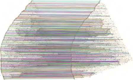
Ch. Ulrich et al. / Imaging the vascular network of the human spleen

   Wan et al. [WBDM13] also use feature detection based                the other direction is the same, some mismatches almost al-
on SURF and thin-plate splines for the non-rigid registra-             ways remain. These are usually filtered out using the random
tion of a set of synthetic brain MRI images. This method               sample consensus algorithm [FB81] or one of its variants.
however requires an exhaustive training step for feature se-
lection and thus cannot be used for “one-shot” specimen
in the context of medical research. Kim et al. [KBFM97]                3. Overview
utilize thin-plate splines for alignment of auto-radiography           The overall registration and alignment algorithm is split
images. They used a low-resolution undistorted video feed              into three steps. First, we determine suitable features in all
as guide images. Again, large structures are required for              scanned sections. Then we use those features to perform an
this method. In contrast to Auer et al. [ARH05] we oper-               initial pairwise rigid alignment of all sections. This alignment
ate on much larger images – complete histological scans at             is used to iteratively deform the images and to identify the fea-
20× magnification. Auer et al. combine a multi-resolution              ture correspondences. The non-rigid alignment is performed
rigid registration with thin-plate spline non-rigid step. We           in such a way, that the overall deformation of the images is
use one-step rigid transform and a B-spline-based non-rigid            minimized. Minimizing the deformation leaves an overall
step. Song et al. [STBM13] register a set of immunostained             rigid transformation of the images as only degree of freedom.
sections with alternated different staining.                           We fix this by preventing rotation and translation of the first
   Existing methods all rely on a reference slice to which all         slice. This means that the remaining ones are rigidly aligned
others are deformed. As shown by Bagci and Bai [BB10],                 to the first, but all of them are deformed. This does not mean
selecting the “best” reference is crucial for the final result.        that the first slide is used as a reference for the distortion of
In contrast to that, we perform a global optimization step to          all other slides. Finally, the deformed images are generated,
minimize the energy of the non-linear distortions of all slides.       forming an aligned stack. Figure 2 shows the overall work
                                                                       flow of our method.

2.3. General Image Registration                                                       Input images
                                                                                                                 Detect
                                                                                                                features
There is an extensive research on image registration and its
various applications. Early works [LK81] date back more                                                      Rigid feature
than 30 years ago. Friston et al. [FAF∗ 95] describe the im-                                                  alignment
age registration process as a least-squares problem where the
                                                                                                            Find pairwise
differences between images are minimized. Several surveys                                no
                                                                                                           correspondences
on image registration methods exist [Bro92, ZF03]. Image
registration, as a process of overlaying different images of                            Iteration           Non-rigid fea-
the same or similar objects typically consists of four phases:                         converged?           ture alignment
feature detection, feature matching, estimation of the trans-
formation, application of the transformation. In our case we
first estimate the rigid transformation and then the non-rigid                                yes
one.                                                                                Deform images             Image stack

2.4. Feature Detection and Matching                                    Figure 2: Overall work flow of our non-rigid registration and
                                                                       alignment algorithm.
Numerous image feature detection algorithms exist. Re-
cent algorithms detect scale and rotation invariant features.
Among them are the SIFT features [Low04], SURF is
their improvement in term of run-time efficiency [BETV08].             4. Initial Rigid Alignment
BRISK [LCS11] aims to further reduce run-time compared                 The purpose of the initial rigid alignment step is to roughly
to SURF without sacrificing the detection quality. Due to the          register the slices and to facilitate the non-rigid alignment.
low run-time and memory consumption, we chose to use this              First, we need to choose adequate feature candidates and then
detector in our work. Further feature detectors can be found           perform a pairwise matching. Based on these matches that
in the survey of Heinly et al. [HDF12]. The n-SIFT [CH09]              still contain a high number of outliers, we then calculate a
is a generalization of SIFT to volume and otherwise multi-             robust alignment.
dimensional data. n-SIFT can be used in the registration of
multiple volume data sets against each other.
                                                                       4.1. Choosing Candidate Features
   After the features are detected, they need to be matched in
pairs between two images. Typically, each feature is matched           The first step we perform for each input image, is finding
with the most similar one in the other image. Despite prun-            all feature points. The slides have been normalized prior to
ing strategies, like only keeping pairs where the matching in          feature detection. For this purpose, we use the BRISK feature

                                                                                                           c The Eurographics Association 2014.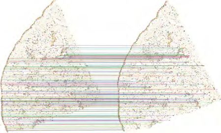
Ch. Ulrich et al. / Imaging the vascular network of the human spleen

detector [LCS11]. Unfortunately, we cannot directly use the
detected features and compute pairs by searching for the
most similar one in the reference image as shown in Figure 3.
The reason for this is that many small features cannot be
reliably used because they originate from single cells or other
common structures.

                                                                            Figure 4: The relative number of false matches is reduced
                                                                            using larger features only. Nevertheless, still many outliers
                                                                            exist. As before, we show only each 10th match to reduce
                                                                            visual clutter.

                                                                            this pair, if
Figure 3: Using standard image registration results in almost
random matches due to ambiguous features. Every 10th match                               1      kPa,tgt − Pb,tgt k
                                                                                              ≤                    ≤ 1 + εg              (2)
is shown only to reduce visual clutter.                                                1 + εg   kPa,ref − Pb,ref k
                                                                                                   kPa,tgt − Pb,tgt k ≥ dmin · simage    (3)
                                                                                                  kPa,ref − Pb,ref k ≥ dmin · simage ,   (4)
   On the other hand, larger features – about an order of
magnitude larger than a single cell – are usually much less                 where Pa,tgt is the position of a in the target image, etc., εg
ambiguous. Therefore, we select the Nselect features in each                the maximum global stretch, with εg ≤ εl , simage the image
input image i whose descriptors have the largest diameters.                 size, and dmin the minimum relative distance between the
Then we compute pairs by selecting the most similar feature                 points. Based on the selected pair, we compute a candidate
in the reference image i − 1. The possible candidates can                   transformation Ri .
again be reduced by exploiting the fact that there is not much
                                                                               In addition to quickly rejecting futile candidates, we also
scaling between structures in adjacent sections. Thus we only
                                                                            augment computing the consensus score with the matching
consider features with a similar descriptor diameter.
                                                                            score of the pairs that are determined as inliers for the given
                          1      dtgt                                       transformation. Instead of simply counting all matches j with
                               ≤      ≤ 1 + εl ,                  (1)
                        1 + εl   dref                                       kRi Pj,tgt − Ri−1 Pj,ref k ≤ simage · εg , we accumulate

where dtgt and dref are the target and reference diameters                                                 1
                                                                                                                     ,                   (5)
respectively, and the threshold εl the maximum local stretch.                                         1 + wmatch δ j
Figure 4 shows the matches found when only using larger                     where δmatch is the difference of the descriptors and wmatch a
features. Although the quality improved, the matches still                  weighting constant.
contain a high amount of outliers and we have to perform a
robust alignment procedure.                                                    After finding a good transformation using the RANSAC
                                                                            algorithm, we again compute the inlier set. From this, we
                                                                            compute a rigid transformation with a weighted least squares
                                                                            error. The weighting is the same that we already used to
4.2. Pairwise Alignment
                                                                            compute the consensus score (see Equation 5). Figure 5 shows
After finding initial pairs, we perform a random sample con-                the found rigid transformation between two sections together
sensus (RANSAC) [FB81] based registration. A rigid trans-                   with the matches in the consensus set.
formation in 2D is defined by two points and their movement.
Actually, this has one degree of freedom more than a rigid
                                                                            5. Non-rigid Alignment
transformation because the distance of points cannot change.
Since we know that the distance between two corresponding                   The non-rigid alignment is an iterative process because each
point pairs on neighboring sections can only change due to                  deformation of the images may change the inlier/outlier clas-
deformation of the specimen, we can restrict the candidate                  sification and thus the matching pairs. We first start by find-
set. We choose two random matches a and b, and only use                     ing a corresponding feature in the reference images. Then

c The Eurographics Association 2014.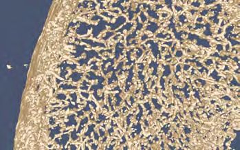
Ch. Ulrich et al. / Imaging the vascular network of the human spleen

Figure 5: Rigid registration between two sections with the               Figure 6: Pairwise matches found in the first iteration, where
consensus set of matching features. Notice that the upper area           only high confidence matches – i.e. weight ≥ 0.2 – are shown.
cannot be aligned due to local deformations.                             Note that despite the increased density of matches, there are
                                                                         still very sparsely covered regions where large deformations
                                                                         are present, e.g. at the top of the image.

we perform a least-squares deformation trying to align all
found pairs. Finally, we compute the feature positions after             following constraint of the control points:
deformation and check if the matches are still valid or if we                              14 14
can find a better correspondence that is now within the local                              ∑ ∑ Bl (u)Bm (v)αil,m = Ri Pj,i ,                 (7)
search radius. If all pairs remain – or if we have performed a                            l=0 m=0

maximum number of iterations itmax – the registration termi-                         ui = u Ti (Pj,i ))    vi = v Ti (Pj,i )) ,              (8)
nates. We do not select a reference slide and deform all slides
                                                                         where u and v are the mappings of a pixel in the aligned
to match it, but rely on global optimization to minimize the
                                                                         image to the parameter values, and αil,m are the control points
energy of the deformation.
                                                                         of the B-spline of image i. Again, we use the same confidence
                                                                         weighting described in Equation 5.
5.1. Finding Pairwise Matches                                              In addition, we want to prevent large deformations and
                                                                         smooth areas where we have no matches. We achieve this by
In each iteration, we first start finding new matches. For each          adding a constraint for each edge of the control meshes:
feature j in image i we search a corresponding feature k
in image i − 1 with the most similar descriptor under the

                                                                                           i         i
                                                                                                                 dx
                                                                                         αl+1,m − αl,m wα =                       (9)
constraint that                                                                                                   0

                                                                                                                0
                                                                                         αil,m+1 − αil,m wα =

           kTi Pj,i − Ti−1 Pk,i−1 k ≤ simage · εg ,         (6)                                                        ,         (10)
                                                                                                                  dy
where Ti is the non-rigid transformation of image i. Note                where dx and dy are the distances between two neighboring
that in the first iteration, this is the rigid transformation Ri .       control points in the output image in x and y direction and wα
Figure 6 shows the matches found in the first iteration.                 is the smoothing weight. Note that this also induces a penalty
                                                                         for rotations but this is unproblematic because we already
                                                                         performed a global rigid alignment.
5.2. Computing Image Deformations
                                                                            Combining all of the constraints leads to a sparse linear
The non-linear deformation is based on a uniform bi-cubic B-             equation system. We solve this using the conjugate gradient
spline over a 9×9 control point grid with three additional con-          method [PTVF07] for sparse matrices. As initial value we
trol points outside the image. The control point net initially           use the control points from the previous iteration. For the
covers the first image. The aligned images are constructed in            first iteration, we simply set αil,m = ((l − 3)dx , (m − 3)dy )T
the parameter domain of the B-spline that is scaled such that            which is a non-deformed control grid.
it has the same size as the first input image. This means that
                                                                            As the first image is not deformed, this leaves an overall
we can simply evaluate the B-spline to compute the source
                                                                         deformation of all images as a degree of freedom. We use
position in the deformed image for each pixel of the output.
                                                                         this to minimize the mean square deformation of all images
   We register each image to the previous one, starting with             after each registration pass. Moving each control point of all
the registration of the second to the first. For each matching           images by the same offset does not change the matching. We
feature pair j, k in image i and i − 1 respectively, we have the         can thus minimize the mean square deformation by moving

                                                                                                              c The Eurographics Association 2014.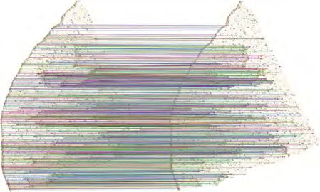
Ch. Ulrich et al. / Imaging the vascular network of the human spleen

the control points, such that the average of each control point
l, m over all images (including the first one) lies on a grid. In
other words, we constrain the control points such that:
                  Nimg
                                 (l − 3)d
                   ∑ αil,m = (m − 3)dxy .                   (11)
                  i=1

  This uses the remaining degrees of freedom in the align-
ment to force the “average deformation” to be zero. Previous
approaches simply fixed a reference slice such that it was not
deformed at all.

5.3. Deforming the Images
To deform the images, we use the OpenCV [Bra00] func-
tion remap. First, we compute the position in the source
image for each pixel of the output image and store it in an
array. Instead of evaluating the complete B-spline function
for each pixel, we can exploit the fact that the image is a
uniform grid. For each row of control points, we evaluate the
1D cubic B-spline for the x-coordinate of each pixel. Then
we only need to compute 1D cubic B-splines instead of bi-
cubic B-splines per pixel. As the number of image lines is
significantly higher than the number of control point rows
we only need to compute 4 basis functions instead of 8 per
pixel and accumulate 4 instead of 16 control points. In total,
this roughly saves 70% of the computation time. Then, the
                                                                            Figure 7: Overview of the complete aligned data set of the
computed pixel location array is used to generate the aligned
                                                                            human spleen specimen. Capillary and larger vessel endothe-
image. For the reconstruction, we use bi-linear filtering.
                                                                            lia and certain fibroblasts are colored brown, visualizing the
                                                                            vascular network.
6. Results
Figure 7 shows an overview of the complete data set of the
human spleen specimen consisting of 24 sections with a reso-                is also compiled as 64 bit. We use the following constants for
lution of 25856 × 32000 pixels each. The thickness of each                  the alignment:
section is approximately 7 µm, so the digitized specimen has                •   Number of features selected per image Nselect = 20, 000
a total thickness of about 170 µm. The image is generated us-               •   Minimum RANSAC edge length dmin = 0.1
ing a volume renderer that combines all sections into a single              •   Maximum local deformation εl = 0.01
thick specimen. Such view would be impossible without the                   •   Maximum global deformation εg = 0.005
registration.                                                               •   Descriptor weight for matches wmatch = 10
                                                                            •   Maximum number of non-rigid iterations itmax = 20
   Figure 8 shows two interesting areas of the spleen speci-
                                                                            •   Smoothing weight wα = 0.2
men. On the left, it shows the shape of a larger artery, dividing
up further until the capillaries, and the right side shows the                 The final matches found for the alignment of two sections
blood supply of a follicle. Single sections do not contain                  are shown in Figure 9. Matching feature pairs have been
longer portions of blood vessel, as Figure 1, second image,                 found for the whole area.
visually depicts. On a larger scale, the shape of the capillary
                                                                               In our experiments we also encountered teared or otherwise
network in the spleen can be reconstructed from our volume
                                                                            damaged slides. Because of our global optimization approach
data using standard visualization algorithms like marching
                                                                            it was possible to register the batch with sufficient accuracy.
cubes (third image).
                                                                            The final aligned data set is shown in Figure 1, right. Although
                                                                            the damage was not “repaired” by our method, it is robust
6.1. Alignment                                                              enough to align all parts.
The complete registration and alignment pipeline is imple-                     Figure 10 compares our registration with the standard ICP
mented in C++ using the OpenCV Library [Bra00] version                      algorithm [BM92]. We used the implementation of Pomer-
2.4.8. The run-times are measured on an Intel Core i7 with                  leau et al. [PCSM13]. Starting from the original images, the
16 GB of RAM running Windows 7 64 bit and the executable                    ICP algorithm converges to a local minimum (top left). Using

c The Eurographics Association 2014.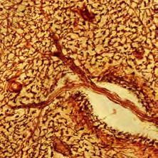
Ch. Ulrich et al. / Imaging the vascular network of the human spleen

Figure 8: In the top left a larger artery develops into a network       Figure 10: Alignment comparison showing the upper right
of smaller vessels. The shape of the blood vessel network               corner of two consecutive spleen sections stained for CD34
in human spleens is unexplored, except for the fact that it             and smooth muscle alpha actin in brown, and for CD271 in
has open ends. The top right image shows the blood supply               blue. Top left: result of the ICP algorithm applied to the orig-
of a lymphatic follicle. The bottom images show similar                 inal images. Top right: ICP with initial manual positioning
structures in the two-color specimen. Such in-depth views of            of the sections. Bottom left: result of our rigid registration.
were impossible so far.                                                 Bottom right: the result of our non-rigid registration (final
                                                                        output of our method).

                                                                           Table 1 shows the timings for the different steps of the
                                                                        algorithm. The initial number of features detected per image
                                                                        is between 430k and 450k, so we keep the 4–5% largest
                                                                        ones. Despite the iterative non-rigid alignment procedure,
                                                                        the actual deformation of the images requires most of the
                                                                        time. This is due to the fact, that the bi-cubic B-spline has
                                                                        to be evaluated for every pixel of the output images. Note
                                                                        that using thin plate splines, this step would take significantly
                                                                        longer due to the high number of matched features. The run
                                                                        times for both data sets were identical since the images have
Figure 9: Final matches found during alignment of two sec-              the same size and both contain 24 slides. Due to the pairwise
tions, where only high confidence matches – i. e. weight                matching and the sparse linear system, our method is linear
≥ 0.2 – are shown. The whole images are densely covered                 in the number of slides.
with correctly matched feature pairs.
                                                                               time          feature       rigid     non-rig.        image
                                                                             (mm:ss)        detection     transf.     transf.        recon.
a manual pre-alignment, it obtains better results (top right).            imagea /pairb       0:42a        0:08b       1:03b          1:17a
Due to the ambiguities, caused by the repetitive structures in            total              16:58         3:20      24:02           30:35
human tissue, a consecutive non-rigid alignment, e. g. using
the method of Chui and Rangarajan [CR03] cannot correctly               Table 1: Execution times for the spleen data sets with 24
align the scans. In contrast to that, our method achieves much          sections. The first line shows the average time for various
better results on the same data with the rigid stage only (bot-         phases of our method that is required per image or pair. The
tom left). The final non-rigid stage (bottom right) drastically         second line shows total time for each phase.
improves the alignment.

                                                                                                             c The Eurographics Association 2014.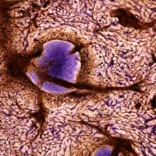
Ch. Ulrich et al. / Imaging the vascular network of the human spleen

7. Conclusion and Limitations                                                  histological images. IEEE Trans. Med. Imaging 29, 9 (2010),
                                                                               1688–1696. 4
After aligning stacks of immunostained spleen serial sections,
                                                                            [BCU12] BAGCI U., C HEN X., U DUPA J.: Hierarchical scale-
we have produced volume renderings of two different speci-                    based multiobject recognition of 3-D anatomical structures. IEEE
men, as well as a 3D-model of the vessels (Figures 1 and 7).                  Trans. Med. Imaging 31, 3 (2012), 777–789. 3
These enable the domain experts to analyze and discuss the                  [BETV08] BAY H., E SS A., T UYTELAARS T., VAN G OOL L.:
shape and function of capillaries and arterial blood vessels in               SURF: Speeded Up Robust Features. Comput. Vision Image
the spleen at a level impossible without our method. Details                  Understanding 110, 3 (2008), 346–359. 4
of interesting areas already discovered are shown in Figure 8.              [BK89] BAJCSY R., KOVAČI Č S.: Multiresolution elastic match-
                                                                              ing. Comput. Vis. Graph. Image Process. 46, 1 (1989), 1–21.
   To achieve this goal, we have presented a method that                      3
is able to robustly register and align immunostained serial
                                                                            [BM92] B ESL P. J., M C K AY N. D.: A method for registration of
sections. This is an especially challenging task due to the                   3-D shapes. IEEE Trans. Pattern Anal. Mach. Intell. 14, 2 (1992),
highly repetitive cellular structures in the tissue. Our algo-                239–256. 3, 7
rithm tolerates relatively large local and global deformations.             [Bra00] B RADSKI G.: The OpenCV Library. Dr. Dobb’s Journal
We measured a global deformation of up to 2% of the image                     of Software Tools (2000). 7
diagonal and a local stretch of up to 5%.                                   [Bro92] B ROWN L. G.: A survey of image registration techniques.
   The most time consuming part of our method is the re-                      ACM Comput. Surv. 24, 4 (1992), 325–376. 4
construction of the deformed images. Therefore, we plan                     [CBP11] C IFOR A., BAI L., P ITIOT A.: Smoothness-guided 3-d
to implement this step on the GPU in the future. A second                     reconstruction of 2-D histological images. NeuroImage 56, 1
                                                                              (2011), 197–211. 3
candidate for a GPU implementation is the conjugate gra-
dient solver which needs most of the time in the non-rigid                  [CBR∗ 11] C HAPPELOW J., B LOCH B. N., ROFSKY N., G ENEGA
                                                                              E., L ENKINSKI R., D E W OLF W., M ADABHUSHI A.: Elastic
alignment phase.                                                              registration of multimodal prostate MRI and histology via multi-
                                                                              attribute combined mutual information. Med. Phys. 38, 4 (2011),
   Although we have developed and used our approach for
                                                                              2005–2018. 3
human spleen specimens, it is much more widely applicable.
                                                                            [CH09] C HEUNG W., H AMARNEH G.: n-SIFT: n-dimensional
Due to the use of feature detection to find similar structures
                                                                              scale invariant feature transform. IEEE Trans. Image Process. 18,
in adjacent sections, our approach is only limited to tissue                  9 (2009), 2012–2021. 4
that contains at least some special histological structures. At
                                                                            [CR03] C HUI H., R ANGARAJAN A.: A new point matching al-
a mesoscopic scale this is however no limitation, as blood                    gorithm for non-rigid registration. Comput. Vision Image Under-
vessels always provide sufficient landmarks in human organs.                  standing 89, 2–3 (2003), 114–141. 3, 8
   While our method appears to be robust even to teared                     [EBG∗ 12] E LICEIRI K. W., B ERTHOLD M. R., G OLDBERG I. G.,
                                                                              I BÁÑEZ L., M ANJUNATH B. S., M ARTONE M. E., M URPHY
or damaged slides, explicitly repairing the damage before
                                                                              R. F., P ENG H., P LANT A. L., ROYSAM B., ET AL .: Biological
alignment would have several advantages. The alignment                        imaging software tools. Nat. Methods 9, 7 (2012), 697–710. 3
will be more precise close to the fracture as there will be
                                                                            [FAF∗ 95] F RISTON K. J., A SHBURNER J., F RITH C. D., P OLINE
consistent feature pairs on both sides. On the other hand, the                J.-B., H EATHER J. D., F RACKOWIAK R. S. J.: Spatial registra-
reconstructed volume will also not be fractured any more. We                  tion and normalization of images. Human Brain Mapping 3, 3
therefore want to develop a method to find and “repair” the                   (1995), 165–189. 4
fractures in the scanned slides.                                            [FB81] F ISCHLER M. A., B OLLES R. C.: Random sample con-
                                                                              sensus: A paradigm for model fitting with applications to image
                                                                              analysis and automated cartography. Commun. ACM 24, 6 (1981),
Acknowledgments                                                               381–395. 4, 5

We would like to thank Anja Seiler and Kathrin Lampp from                   [GBB∗ 01] G UEST E., B ERRY E., BALDOCK R., F IDRICH M.,
                                                                              S MITH M.: Robust point correspondence applied to two- and
Philipps-University Marburg for producing the sections and                    three-dimensional image registration. IEEE Trans. Pattern Anal.
performing the immunostaining. In addition, we thank San-                     Mach. Intell. 23, 2 (2001), 165–179. 3
dra Iden and Astrid Schauss from the CECAD Cluster of                       [Gos05] G OSHTASBY A. A.: 2-D and 3-D image registration: for
Excellence at University Cologne and Verena Wilhelmi from                     medical, remote sensing, and industrial applications. Wiley, 2005.
Philipps-University Marburg for helping a lot with the image                  3
acquisition.                                                                [GTN03] G EFEN S., T RETIAK O., N ISSANOV J.: Elastic 3-D
                                                                              alignment of rat brain histological images. IEEE Trans. Med.
                                                                              Imaging 22, 11 (2003), 1480–1489. 3
References
                                                                            [GvdLP∗ 06] G ILHUIS H. J., VAN DER L AAK J. A., P OMP J.,
[ARH05] AUER M., R EGITNIG P., H OLZAPFEL G.: An automatic                    K APPELLE A. C., G IJTENBEEK J. M., W ESSELING P.: Three-
  nonrigid registration for stained histological sections. IEEE T.            dimensional (3D) reconstruction and quantitative analysis of the
  Image Process. 14, 4 (2005), 475–486. 4                                     microvasculature in medulloblastoma and ependymoma subtypes.
                                                                              Angiogenesis 9, 4 (2006), 201–208. 3
[BB10] BAGCI U., BAI L.: Automatic best reference slice se-
  lection for smooth volume reconstruction of a mouse brain from            [GWM∗ 05]      G IJTENBEEK J. M., W ESSELING P., M AASS C.,

c The Eurographics Association 2014.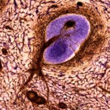
Ch. Ulrich et al. / Imaging the vascular network of the human spleen

  B URGERS L., VAN DER L AAK J. A.: Three-dimensional recon-               [RPMA01] ROCHE A., P ENNEC X., M ALANDAIN G., AYACHE
  struction of tumor microvasculature: simultaneous visualization of         N.: Rigid registration of 3-D ultrasound with MR images: a new
  multiple components in paraffin-embedded tissue. Angiogenesis              approach combining intensity and gradient information. IEEE
  8, 4 (2005), 297–305. 3                                                    Trans. Med. Imaging 20, 10 (2001), 1038–1049. 3
[HBHH01] H ILL D. L. G., BATCHELOR P. G., H OLDEN M.,                      [RSH∗ 99] RUECKERT D., S ONODA L. I., H AYES C., H ILL D.
  H AWKES D. J.: Medical image registration. Phys. Med. Biol. 46,            L. G., L EACH M. O., H AWKES D.: Nonrigid registration using
  3 (2001), R1–R45. 3                                                        free-form deformations: application to breast MR images. IEEE
                                                                             Trans. Med. Imaging 18, 8 (1999), 712–721. 3
[HDF12] H EINLY J., D UNN E., F RAHM J.-M.: Comparative
  evaluation of binary features. In Computer Vision – ECCV 2012,           [SBS11] S TEINIGER B., B ETTE M., S CHWARZBACH H.: The
  LNCS 7573. Springer, 2012, pp. 759–773. 4                                  open microcirculation in human spleens: a three-dimensional ap-
                                                                             proach. J. Histochem. Cytochem. 59, 6 (2011), 639–648. 3
[HH10] H AJNAL J. V., H ILL D. L.: Medical image registration.
  CRC press, 2010. 3                                                       [Sch06] S CHERZER O. (Ed.): Mathematical models for registra-
                                                                              tion and applications to medical imaging. Springer, 2006. 3
[JS01] J ENKINSON M., S MITH S.: A global optimisation method
   for robust affine registration of brain images. Med. Image Anal. 5,     [SFCT12] S AALFELD S., F ETTER R., C ARDONA A., T OMAN -
   2 (2001), 143–156. 3                                                       CAK P.: Elastic volume reconstruction from series of ultra-thin
                                                                             microscopy sections. Nat. Methods 9, 7 (2012), 717–720. 3
[JWC∗ 06]    J U T., WARREN J., C ARSON J., B ELLO M., K AKA -
   DIARIS  I., C HIU W., T HALLER C., E ICHELE G.: 3D volume               [SRB03] S TEINIGER B., RÜTTINGER L., BARTH P. J.: The three-
  reconstruction of a mouse brain from histological sections using           dimensional structure of human splenic white pulp compartments.
  warp filtering. J. Neurosci. Methods 156, 1–2 (2006), 84–100. 3            J. Histochem. Cytochem. 51, 5 (2003), 655–663. 3

[KBFM97] K IM B., B OES J. L., F REY K. A., M EYER C. R.:                  [SRQ∗ 01] S CHNABEL J. A., RUECKERT D., Q UIST M., B LACK -
                                                                             ALL J. M., C ASTELLANO -S MITH A. D., ET AL .: A generic
  Mutual information for automated unwarping of rat brain autora-
  diographs. NeuroImage 5, 1 (1997), 31–40. 4                                framework for non-rigid registration based on non-uniform multi-
                                                                             level free-form deformations. In Medical Image Computing and
[LCS11] L EUTENEGGER S., C HLI M., S IEGWART R. Y.: BRISK:                   Computer-Assisted Intervention, LNCS 2208. Springer, 2001,
  Binary robust invariant scalable keypoints. In IEEE Conf. Com-             pp. 573–581. 3
  puter Vision (2011), ICCV ’11, IEEE, pp. 2548–2555. 4, 5
                                                                           [SSKH10] S HAMS R., S ADEGHI P., K ENNEDY R., H ARTLEY R.:
[LK81] L UCAS B. D., K ANADE T.: An iterative image registration             A survey of medical image registration on multicore and the GPU.
  technique with an application to stereo vision. In Proc. Intl. Joint       IEEE Signal Process Mag. 27, 2 (2010), 50–60. 3
  Conf. Artificial Intelligence (1981), IJCAI ’81, pp. 674–679. 4
                                                                           [STBM13] S ONG Y., T REANOR D., B ULPITT A., M AGEE D.:
[Low04] L OWE D. G.: Distinctive image features from scale-                  3D reconstruction of multiple stained histology images. Journal
  invariant keypoints. Int. J. Comput. Vision 60, 2 (2004), 91–110.          of Pathology Informatics 4, 2 (2013), 7. 4
  4                                                                        [SWL05] S URU J. S., W ILSON D. L., L AXIMINARAYAN S.:
[MBNV04] M ALANDAIN G., BARDINET E., N ELISSEN K., VAN -                     Handbook of biomedical image analysis, vol. 3. Springer, 2005. 3
  DUFFEL W.: Fusion of autoradiographs with an MR volume using             [Thi98] T HIRION J.-P.: Image matching as a diffusion process: an
  2-D and 3-D linear transformations. NeuroImage 23, 1 (2004),               analogy with Maxwell’s demons. Med. Image Anal. 2, 3 (1998),
  111–127. 3                                                                 243–260. 3
[MLW∗ 08] M A B., L IN Z., W INKELBACH S., L INDENMAIER                    [TK11] TANACS A., K ATO Z.: Fast linear registration of 3D
  W., D ITTMAR K. E.: Automatic registration of serial sections              objects segmented from medical images. In Conf. Biomedical
  of mouse lymph node by using image-reg. Micron 39, 4 (2008),               Engineering and Informatics (2011), BMEI ’11, pp. 294–298. 3
  387–396. 3
                                                                           [vKTVHW85] VAN K RIEKEN J. H., T E V ELDE J., H ERMANS
[MvGR∗ 11] M URPHY K., VAN G INNEKEN B., R EINHARDT J.,                      J., W ELVAART K.: The splenic red pulp; a histomorphometrical
  K ABUS S., D ING K., ET AL .: Evaluation of registration methods           study in splenectomy specimens embedded in methylmethacrylate.
  on thoracic CT: The EMPIRE10 challenge. IEEE T. Med. Imaging               Histopathology 9, 4 (1985), 401–416. 3
  30, 11 (2011), 1901–1920. 3
                                                                           [WBDM13] WAN T., B LOCH B. N., DANISH S., M ADABHUSHI
[NHN∗ 03] N IKOU C., H EITZ F., N EHLIG A., NAMER I. J.,                     A.: A novel point-based nonrigid image registration scheme based
  A RMSPACH J.-P.: A robust statistics-based global energy function          on learning optimal landmark configurations. In Medical Imaging
  for the alignment of serially acquired autoradiographic sections.          2013: Image Processing (2013), Proc. SPIE 8669, pp. 866934–
  J. Neurosci. Methods 124, 1 (2003), 93–102. 3                              866934–12. 4
[ORS∗ 01] O URSELIN S., ROCHE A., S UBSOL G., P ENNEC X.,                  [WPFS05] W IRTZ S., PAPENBERG N., F ISCHER B., S CHMITT
  AYACHE N.: Reconstructing a 3D structure from serial histologi-            O.: Robust and staining-invariant elastic registration of a series of
  cal sections. Image & Vision Comput. 19 (2001), 25–31. 3                   images from histologic slices. In Proc. SPIE (2005), Proc. SPIE
                                                                             5747, pp. 1256–1262. 3
[PCSM13] P OMERLEAU F., C OLAS F., S IEGWART R., M AGNE -
  NAT S.: Comparing ICP variants on real-world data sets. Auton.           [WVA∗ 96] W ELLS III W. M., V IOLA P., ATSUMI H., NAKA -
  Robot 34, 3 (Feb. 2013), 133–148. 7                                        JIMA S., K IKINIS R.: Multi-modal volume registration by maxi-
                                                                             mization of mutual information. Med. Image Anal. 1, 1 (1996),
[PLD05] P ENG H., L ONG F., D ING C.: Feature selection based
                                                                             35—51. 3
  on mutual information criteria of max-dependency, max-relevance,
  and min-redundancy. IEEE Trans. Pattern Anal. Mach. Intell. 27,          [XF04] X IE Z., FARIN G.: Image registration using hierarchical
  8 (2005), 1226–1238. 3                                                     B-splines. IEEE Trans. Visual Comput. Graphics 10, 1 (2004),
                                                                             85–94. 3
[PTVF07] P RESS W. H., T EUKOLSKY S. A., V ETTERLING
  W. T., F LANNERY B. P.: Numerical Recipes: The Art of Sci-               [ZF03] Z ITOVÁ B., F LUSSER J.: Image registration methods: a
  entific Computing, 3 ed. Cambridge University Press, 2007. 6               survey. Image & Vision Comput. 21, 11 (2003), 977–1000. 4

                                                                                                                   c The Eurographics Association 2014.
You can also read