Impact of robot antenna calibration on dual frequency smartphone based high accuracy positioning: a case study using the Huawei Mate20X
←
→
Page content transcription
If your browser does not render page correctly, please read the page content below
GPS Solutions (2021) 25:15
https://doi.org/10.1007/s10291-020-01048-0

 ORIGINAL ARTICLE

Impact of robot antenna calibration on dual‑frequency
smartphone‑based high‑accuracy positioning: a case study using
the Huawei Mate20X
Francesco Darugna1,2 · Jannes B. Wübbena1 · Gerhard Wübbena1 · Martin Schmitz1 · Steffen Schön2 ·
André Warneke1

Received: 8 June 2020 / Accepted: 15 October 2020
© The Author(s) 2020

Abstract
The access to Android-based Global Navigation Satellite Systems (GNSS) raw measurements has become a strong motivation
to investigate the feasibility of smartphone-based positioning. Since the beginning of this research, the smartphone GNSS
antenna has been recognized as one of the main limitations. Besides multipath (MP), the radiation pattern of the antenna
is the main site-dependent error source of GNSS observations. An absolute antenna calibration has been performed for the
dual-frequency Huawei Mate20X. Antenna phase center offset (PCO) and variations (PCV) have been estimated to correct
for antenna impact on the L1 and L5 phase observations. Accordingly, we show the relevance of considering the individual
PCO and PCV for the two frequencies. The PCV patterns indicate absolute values up to 2 cm and 4 cm for L1 and L5,
respectively. The impact of antenna corrections has been assessed in different multipath environments using a high-accuracy
positioning algorithm employing an undifferenced observation model and applying ambiguity resolution. Successful ambigu-
ity resolution is shown for a smartphone placed in a low multipath environment on the ground of a soccer field. For a rooftop
open-sky test case with large multipath, ambiguity resolution was successful in 19 out of 35 data sets. Overall, the antenna
calibration is demonstrated being an asset for smartphone-based positioning with ambiguity resolution, showing cm-level
2D root mean square error (RMSE).

Keywords Absolute robot antenna calibration · GNSS · Smartphone-based high-accuracy positioning

 Introduction

 The Global Navigation Satellite System (GNSS) antenna
 quality is a crucial factor in smartphone-based positioning.
* Francesco Darugna
 The use of an omnidirectional linearly polarized antenna in
 francesco.darugna@geopp.de
 mobile devices has advantages in terms of received signal
 Jannes B. Wübbena
 strength and the number of received signals (Pathak et al.
 jannes.wuebbena@geopp.de
 2003), but also makes the antenna very sensitive to mul-
 Gerhard Wübbena
 tipath (MP) effects. This is generally accepted since the
 gerhard.wuebbena@geopp.de
 design drivers of smartphone antennas (e.g., continuous
 Martin Schmitz
 signal reception in any location) lead to seeking the highest
 martin.schmitz@geopp.de
 sensitivity. Moreover, the smartphone antenna is affected
 Steffen Schön
 by the other components of these portable devices, e.g., the
 schoen@ife.uni‑hannover.de
 screen of the cell phone (Xiao et al. 2019). The high levels
 André Warneke
 of non-suppressed local MP cause significant and hard to
 andre.warneke@geopp.de
 predict phase errors, making ambiguity resolution even more
1
 Geo++ GmbH, Steinriede 8, 30827 Garbsen, Germany challenging, as pointed out by Pesyna Jr et al. (2014) and
2
 Institut für Erdmessung, Schneiderberg 50, 30167 Hannover, Humphreys et al. (2016). Smartphone-based high-accuracy
 Germany

 13
 Vol.:(0123456789)
15 Page 2 of 12 GPS Solutions (2021) 25:15

positioning is therefore challenging, but several studies sug- To our knowledge, no attempt to perform an absolute
gest that, under some pre-requisites, it is feasible. antenna calibration for a smartphone has yet been pub-
 Multiple authors investigated the quality of smartphone lished. Netthonglang et al. (2019) computed an approxi-
GNSS measurements (Massarweh et al. 2019) and devel- mated antenna phase center of the Xiaomi Mi8 smartphone
oped strategies to improve positioning results in precise by averaging the post-processing coordinates in northing and
point positioning (PPP) type solutions without ambiguity easting. Their study showed centimeter-level relative posi-
resolution (Zhang et al. 2018; Wu et al. 2019). tioning using roughly 5 and 20 km baselines after mainly
 Various research groups investigated the potential of removing the multipath effects. Wanninger and Heßelbarth
ambiguity resolution with a smartphone receiver, using an (2020) presented results of a relative calibration of the L1
external GNSS antenna. Humphreys et al. (2016) suggested frequency of a Huawei P30 with respect to a geodetic refer-
that smartphones seem to be fully capable of supporting cm- ence antenna. With the calibration, they were able to achieve
accurate carrier-phase differential GNSS positioning when 2 cm-accurate positioning after 60 min of convergence.
placed in appropriate locations. For example, Geng and Li Here, we perform an absolute, multi-frequency antenna
(2019) show that with a Xiaomi Mi8 smartphone coupled calibration exemplarily for a Huawei Mate20X phone. We
with an external antenna, it is possible to obtain a reliable employ the robot-based absolute antenna field calibration
ambiguity-fixed solution. (Wübbena et al. 1997, Wübbena et al. 2000, Schmitz et al.
 A different approach to achieve ambiguity resolution with 2002, Rothacher 2001) to retrieve PCO and PCV correc-
smartphones is to directly use the smartphone antenna but tions. These parameters are demonstrated to be an asset to
employ the phone in specifically designed test cases with smartphone-based positioning. The impact of antenna cor-
highly reduced multipath. Darugna et al. (2019) demon- rections on the positioning performance is investigated,
strated that ambiguity resolution is indeed possible with and the outcome is reported. In the first section, we present
smartphones when used with a choke ring type of ground the robot antenna calibration concept, along with the PCV
plane on a moving platform. Bochkati et al. (2020) show description. Successively, we discuss the resulting PCV
comparable results when the smartphone is undergoing a pattern. In the following section, the positioning results are
slow circular motion. reported after applying the antenna corrections, showing
 The site-dependent effects of GNSS measurements are high-accuracy positioning with fixed ambiguities in open
only partly due to reflections in the vicinity of the antenna. sky environments. Finally, we summarize the main conclu-
Another contribution is the signal reception in the antenna sions and suggest possible future work.
itself. In the case of phase observations, these distortions
are called phase center variations (PCV) and refer to a mean
center, an imaginary point thought of as the point where the
signals are on average received. This center does typically Absolute robot‑based field calibration
not align with the antenna reference point (ARP), which is of GNSS antennas
a well-defined point accessible from outside the antenna.
The mean phase center and the geometric offset to the ARP PCV are not homogenous in space. They can be expressed
define the so-called phase center offset (PCO), which is as a function of two angles: azimuth and zenith . As pre-
the vector between ARP and mean phase center, pointing sented in Rothacher et al. (1995), such a function can be
toward the mean phase center. Here, we report on the PCV expanded with spherical harmonics. Accordingly, the PCV
computed for L1 and L5 frequencies derived from a com- can be described as:
mon adjustment of GPS and Galileo observations. Nowa- nmax n
days, high precision applications require mm-level PCV
 ∑ ∑
 PCV( , ) = [Anm cos (m ) + Bnm sin(m )]Pnm cos ( ).
for the most extensive elevation range possible (Teunissen n=0 m=0
and Montenbruck, 2017). The full description of the phase (1)
behavior is called antenna correction, and the procedure to In Eq. 1, and refer to the position of a specific satellite
determine PCO and PCV is called antenna calibration. Dur- in the antenna coordinate system, Pnm are the fully normal-
ing the years, many working groups developed antenna cali- ized Legendre polynomials, and Anm and Bnm are the coef-
bration techniques, e.g., anechoic chamber measurements ficients estimated for maximum degree nmax and maximum
(Schupler et al. 1994), relative field calibrations (Rothacher order mmax ≤ nmax.
et al. 1995; Mader 1999), and absolute field calibrations It is worth observing that the PCV depend on the fre-
(Wübbena et al. 1997, 2000; Menge 2003; Kersten 2014, quency of the received signal, being independent of the
Willi 2019). A comparison between the chamber and abso- GNSS involved (here, GPS and Galileo). Therefore, the
lute field calibrations can be found in Görres et al. (2006) results are the same for L1-E1 and L5-E5a and here reported
and Willi et al. (2020). equivalently.

13
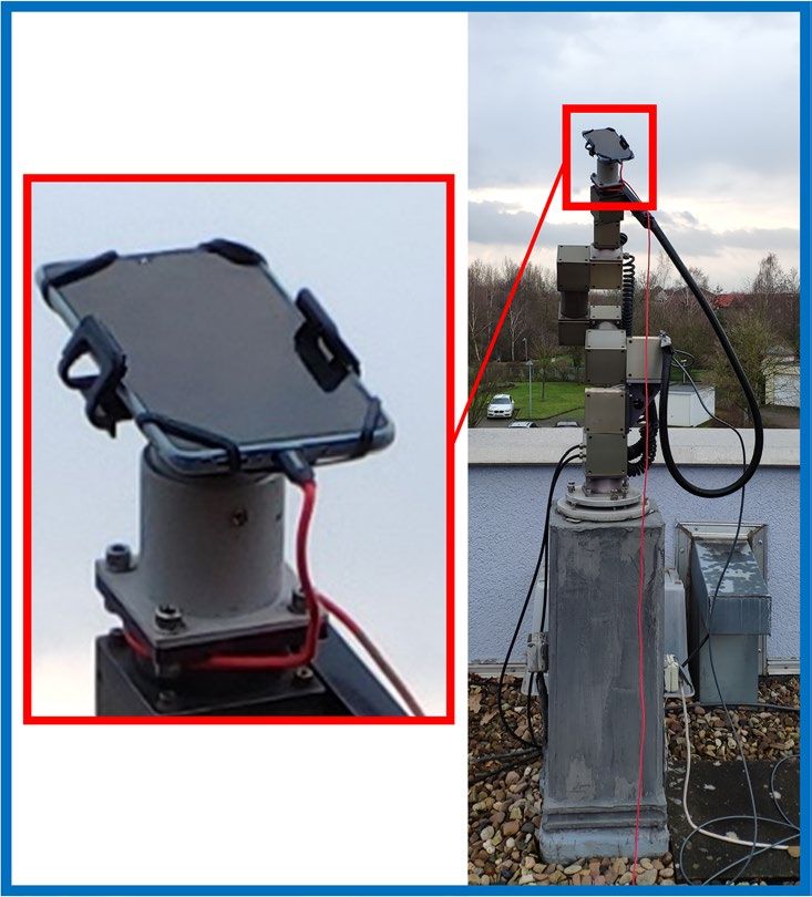
GPS Solutions (2021) 25:15 Page 3 of 12 15

 The antenna calibration provides the antenna correc- At the end of the process, antenna corrections in the
tions, i.e., PCO and PCV, applied to the positioning algo- ANTEX format (Rothacher and Schmid, 2010) are gener-
rithm. Since in a GNSS observation equation, the effect ated to describe the elevation- and azimuth-dependent PCV
of the two sources of station dependent errors cannot be completely. In the following paragraph, the results of the
distinguished, the determination of PCV or MP requires calibration are applied in smartphone positioning.
the elimination or separation of one of the two (Schmitz
et al. 2002). The rapid movement of the robot used in robot Analysis of smartphone’s PCV
antenna calibration causes a change in the antenna orienta-
tion (rotations, tilts), introducing a variation of only the The magnitude of the PCV is shown in Figs. 2 and 3 for L1
PCV every epoch, thus allowing the separation between and L5 frequency, respectively. PCV magnitudes up to about
antenna errors and multipath. This effect is taken into 2 cm and 4 cm are observed for L1 and L5, respectively,
account in the Kalman filter process, where the residual with formal STDs (1 ) lower than 1.6 mm. These STDs are
multipath is estimated as a stochastic process with a cor- related to the variance–covariance matrix of the whole state
relation length of 60 s (Wübbena et al. 2000), allowing to estimation process. Consequently, they are affected by both
assess the antenna phase variation through fast orientation the estimation of the parameters of the spherical harmon-
changes. Several thousands of robot positions are evalu- ics and the quality of the observations. The variations over
ated through the tilts and rotations, allowing to define the azimuth and elevation of the magnitude of the estimated
shape of the PCV. The azimuth- and elevation-dependent PCV values are 7 mm and 10 mm for L1 and L5 frequen-
PCV are described by a spherical harmonic expansion cies. The Mate20X PCV are larger than those of a typical
(see (1)). We used spherical harmonics of degree eight rover antenna that shows typically PCV lower than 10 mm,
and order five. Moreover, the PCV are centered to zero with a variation smaller than 2 mm. The largest magnitudes
for zenith angles equal to zero, i.e., PCV( = 0) = 0 . We of the PCV occur for azimuthal angles ∈ [270◦ , 360◦ [ for
refer to Wübbena et al. (1997), Wübbena et al. (2000) and the L1 frequency (see Fig. 2) and for ∈ [230◦ , 360◦ [ for the
Schmitz et al. (2002) for further details about the concept L5 frequency (Fig. 3). Comparing Figs. 2, 3, and 4, it can
of the robot-based absolute antenna calibration. be observed that the largest absolute values of PCV are in
 Figure 1 shows the setup for the antenna calibration of directions of the major part of the smartphone’s body with
the smartphone and the simplified dataflow to estimate respect to the antenna phase center locations. The smart-
the antenna corrections. The Mate20X was mounted on phone components (housing and active electronics), as well
the robot, aligning the geometrical center of the smart- as near field effects in that direction, might affect the signal
phone with the rotational center of the robot. In this case, reception resulting in larger PCV.
the rotational center corresponds to the ARP. The smart- Twelve distinct antenna calibrations have been carried
phone’s observations acquired during the calibration have out with the Mate20X to assess the repeatability of the
been post-processed in a multi-frequency GNSS antenna absolute PCV. A single antenna calibration duration goes
calibration along with GNSS observations from a geodetic from a minimum of six hours to a maximum of 37 h. As an
reference station. example, Fig. 5 and 6 show the magnitude of the difference

Fig. 1  From left to right: robot
 Antenna Geodetic
antenna calibration setup and
 under test antenna
simplified processing scheme of on the robot Ephemeris
the calibration of the smart-
phone antenna. The Mate20X
was carefully mounted, allow-
ing the device to be continu-
 Robot Reference
ously charged
 orientation site
 + +
 Rinex Rinex

 GNSMART

 ANTEX files
 (PCV)

 13
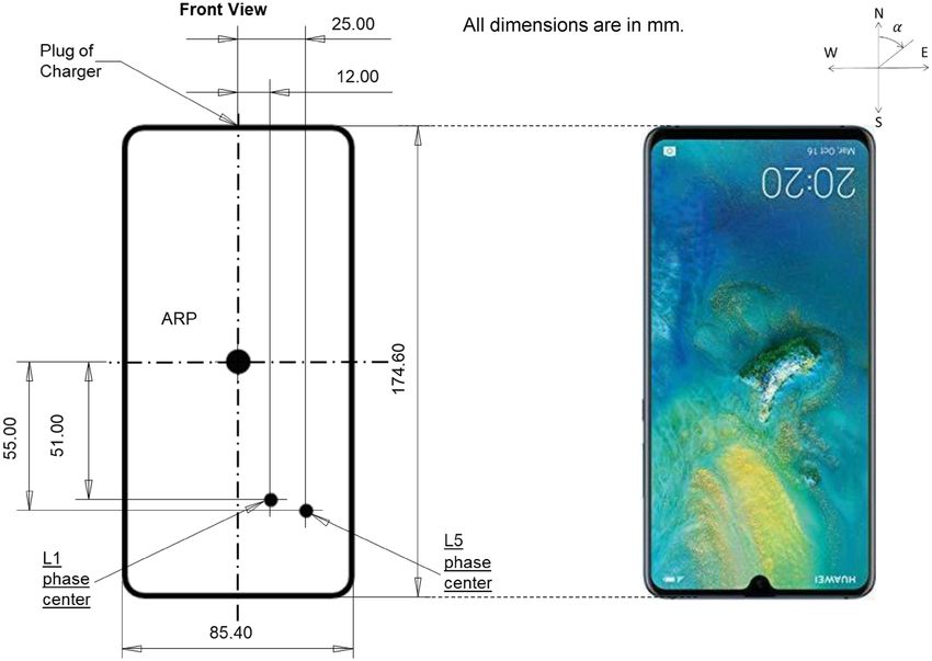
15 Page 4 of 12 GPS Solutions (2021) 25:15

Fig. 2  L1 PCV of the Mate20X
smartphone antenna. Polar and
3D plot with respect to azimuth
and elevation are reported

Fig. 3  L5 PCV of the Mate20X
smartphone antenna. Polar and
3D plot with respect to azimuth
and elevation are reported

Fig. 4  Location of the estimated
phase centers for L1 and L5
frequencies within the Mate20X
and the north definition of the
antenna calibration. The larger
magnitudes of PCV depicted in
Figs. 2 and 3 are in correspond-
ence of the opposite corner of
the antenna phase center loca-
tions. All the dimensions are
reported in mm. The plug of the
charger is defined as the NRP

13

GPS Solutions (2021) 25:15 Page 5 of 12 15

Fig. 5  Example of L1 PCV
difference between a single
calibration and the type mean.
Polar and 3D plot with respect
to azimuth and elevation are
reported

Fig. 6  Example of L5 PCV
difference between a single
calibration and the type mean.
Polar and 3D plot with respect
to azimuth and elevation are
reported

between the correction values of a single calibration of 12 h a rover antenna, i.e., lower than about 4 mm at the horizon
and the type mean correction computed from all calibrations. and, on average, roughly 1 mm between 15 and 20 deg.
In the type mean correction, a rigorous adjustment of the To our knowledge, no published information concern-
individual PCV spherical harmonic expansions with their ing the Mate20X antenna type and location is available.
complete variance–covariance matrix is executed (Wübbena However, following what was reported by other authors
et al. 2006). Some elevation-dependent considerations can (Banville et al. 2019, Lachapelle and Gratton 2019), the
be drawn from the comparisons shown in Fig. 5 and Fig. 6. Mate20X is equipped with an omnidirectional linearly
The agreement between the type mean and the individual polarized antenna. Different factors might contribute to
calibration is better than 5 mm for elevations higher than the larger PCV variation of the L5 differences. The L5
20°. For low elevations, significant discrepancies are vis- tracking performance and the geometry of the constel-
ible for the azimuth angle ranges mentioned above. This is lation of L5-capable satellites are not optimal (because
uncommon for the antenna calibration and may be attributed not all the GPS satellites broadcast L5). Furthermore, the
to the capability to calibrate the smartphone antenna in those Mate20X is equipped with two antennas. Figure 4 shows
particular elevation and azimuth regions. the location of the estimated antenna centers along with
 In addition, for each calibration, the deviation from the the computed PCO. In Fig. 4, the orientation angle is the
type mean is computed for the elevation-dependent PCV and azimuth angle introduced in (1). In the calibration setup,
shown in Fig. 7. The PCV differences indicate a deviation the plug of the charger is defined as the North Reference
of up to 4 mm for L1 and 12 mm for L5, especially for high Point (NRP), as shown in Fig. 4. The dimensions reported
elevations. These values are larger than usually observed for in Fig. 4 have small uncertainties up to few mm due to

 13

15 Page 6 of 12 GPS Solutions (2021) 25:15

 Application of antenna corrections:
 positioning results

 The PCO and PCV corrections obtained from the calibra-
 tion have been applied in the positioning algorithm of the
 GNSMART software to perform smartphone-based posi-
 tioning. The PCO can be expressed in terms of PCV (Leick
 et al. 2015). Therefore hereafter, we refer to PCV as the
 total contribution. The concept behind the employed posi-
 tioning algorithm is state space modeling (SSM). The main
 description of the SSM approach can be found in Wübbena
 and Willgalis (2001), and Wübbena et al. (2001). For the
 tests, we assume that the two receivers experience the same
 atmospheric effects. The post-processing algorithm employs
 an extended Kalman filter (EKF), and an elevation mask of
 10 degrees is applied. We achieved ambiguity-fixed epochs
 with at least four satellites fixed to integers successfully. A
 satellite has been considered fixed when the ambiguity is
 fixed to an integer value for two frequencies (i.e., L1 and
 L5). The ratio test shows values higher than 3, being coher-
 ent with what is suggested by Euler and Schaffrin (1991).
 To evaluate the impact of the antenna corrections, we
Fig. 7  Elevation-dependent difference from type mean of the esti- carried out tests in different environments. Since the smart-
mated L1 (top row) and L5 (bottom row) PCV computed for each
 phone antenna is susceptible to MP, we collected some
calibration
 measurements on a soccer field (see Fig. 8) to prevent signif-
 icant ground reflections. The soccer field is located roughly
the precision in positioning the mechanical mount used in 12 km northwest from a geodetic reference station in Garb-
the calibration setup. A 1 cm distance (in E-W direction) sen, Germany. The second environment considered is an
between the two estimated centers is observed. Besides, open sky environment on the rooftop of the Geo++ building
the Up component of the PCO is 2 mm and 7 mm for L1 (see Fig. 9) in Garbsen. In the same rooftop conditions and
and L5, respectively. measurements from the same smartphone model, Darugna
 et al. (2019) already showed that it is not possible to solve
 ambiguities reliably because of the residual phase biases
 possibly caused by multipath.

Fig. 8  Soccer field setup. Left
and middle panel: the geodetic
receiver has been used to com-
pute the correct reference posi-
tion of the smartphone. Right
panel: the Mate20X has been
aligned to geographic north,
with the bottom edge eccentric
over the reference point (the
hole in the piece of cardboard)

13

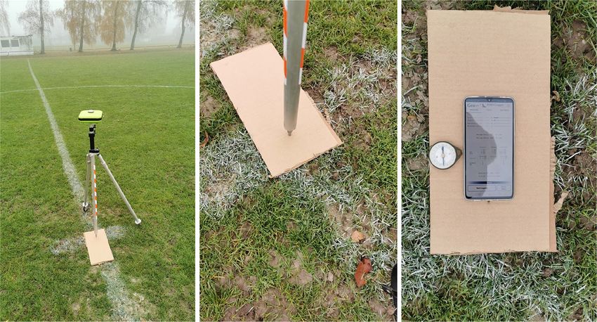
GPS Solutions (2021) 25:15 Page 7 of 12 15

Fig. 9  Rooftop and multipath environment of the Geo++  building.
The pillars within the red squares were chosen as locations for the
smartphone tests

Soccer field test
 Fig. 10  Positioning performance in the soccer field: the Mate20X is
 the rover and the JAVAD receiver about 50 m away is the reference
Figure 8 shows the setup used to perform the measurements. station. The 2D error obtained with and without PCV is compared.
First, we installed a JAVAD geodetic receiver over the Results with float and resolved (AR) ambiguities are reported
center of the pitch. We compute the position of the geodetic
receiver using a reference station at the Geo++ building
(see Fig. 9), roughly 12 km away. The resulting coordinates than 180 s. While also improving the float solution for most
are then used as a reference to evaluate the quality of the of the time, the primary outcome of the experiment is that
smartphone-based positioning.
 Second, we laid down the Mate20X on the ground ori-
enting the NRP toward north properly and the bottom edge
over the reference point coordinated with the geodetic
receiver (right panel). We evaluate the performance of the
smartphone-based positioning for a local and a remote refer-
ence station. The local reference was the geodetic receiver
placed over the penalty point, roughly 50 m away, and the
remote setup used the stationary reference station at the
Geo++  building, 12 km away. About 30 min of measure-
ments was gathered and analyzed.
 Figures 10 and 11 show the improvement in positioning
that antenna calibration can provide in terms of 2D error.
Float and ambiguity resolved results are shown in the two
figures, with and without antenna corrections. Figure 10
depicts the 2D positioning error obtained with respect to
the local geodetic receiver on the pitch, while Fig. 11 shows
the results with respect to the reference station 12 km away.
Both figures suggest that the ambiguities were fixed cor-
rectly to integers when applying the PCV in both experi-
ments, yielding a 1.5 cm and 3.9 cm 2D error, respectively.
The RMSE in the height component is 3.5 cm and 6.1 cm,
respectively. The larger values for the remote setup are
 Fig. 11  Positioning performance in the soccer field: the Mate20X is
expected since the atmospheric conditions have a stronger the rover while the reference station is about 12 km away. The 2D
influence on the long baseline. In both cases, the time to error obtained with and without PCV corrections is compared.
fix ambiguities (TTFA) of at least four satellites is lower Results with float and resolved (AR) ambiguities are reported

 13

15 Page 8 of 12 GPS Solutions (2021) 25:15

the use of antenna corrections opens the possibility to fix observations are available). In the first case (Fig. 12), correct
ambiguities correctly. ambiguity resolution was not possible, while it was in the
 second case. Figure 12 shows poor position dilution of preci-
Rooftop test sion (PDOP) both for GPS single-frequency and for Galileo
 dual-frequency, while the same parameters are significantly
To further evaluate the impact of the antenna corrections better in Fig. 13, giving a good indication of why ambiguity
on ambiguity resolution, a local setup on the roof of the resolution was only possible in the latter case. In addition,
Geo++ building is considered. It is an open sky environ- for the sake of completeness, geometric (G), horizontal (H),
ment, where several pillars with known coordinates present and vertical (V) DOP are reported. Also, Figs. 12 and 13
favorable locations for GNSS testing. The observations of a show the number of usable satellites is much lower for the
close (< 10 m) reference station have been exploited using smartphone than the geodetic reference receiver, with num-
the same positioning approach as in the soccer field test. bers as low as 3 or 4 per constellation. This means that there
Here, the repeatability of the performance comparable to the is often not much redundancy in the positioning solution
soccer field test case is investigated in more detail. and a single satellite with increased measurement errors can
 As shown in Fig. 9, three different pillars were chosen easily make the difference between a reliable and noisy posi-
as support for the smartphone (the pillars are squared in tioning solution. It is worth mentioning that a small PDOP
red color). The three pillars are differently affected by the does not assure a successful ambiguity resolution (Wang
small building-block on the top left corner that can be seen et al. 2020). However, it is shown that simple considerations
in Fig. 9. The smartphone was placed on the surface of the about geometry and signal strength provide the user with a
pillar, with the screen facing up and with the NRP correctly fast apriori indication about obtaining a precise solution with
oriented toward north. The device lies directly on top of the smartphone’s measurements based only on the geometry.
pillar to remove ground reflections, which can significantly Figure 14 shows the significant impact of the PCV cor-
affect the measurements. We collected 35 samples of obser- rections for the 19 high-quality measurements on the differ-
vations over the three pillars on five different days of the year ent pillars. While for all datasets only float solutions could be
(DOY) in 2019: 234, 235, 338, 340, 344. In 54% (19 out of achieved without corrections, a centimeter-level fixed posi-
35) of the samples, we achieved a solution with successfully tioning was possible when applying them. Figure 14 indicates
fixed ambiguities. that, like in the pitch case, the antenna corrections improve
 To understand the underlying reason for the success or the float solution by roughly 1 cm. When applying the antenna
failure of fixing, we investigated the satellite geometry and corrections, a 2D RMSE of 1.6 cm and an RMSE of 3.8 cm in
the measured signal strength for the different datasets. A the height component can be achieved when the ambiguities
representative comparison between good and bad geometry are successfully fixed to integers (see Fig. 14 and Table 1).
is reported in the following example. Figures 12 and Fig. 13 The time to fix ambiguities (TTFA) is less than 3 min in 84%
show two different observation periods for the phase meas- of the cases, while all the 19 samples are fixed in less than
urements of GPS single-frequency (L1 or L5 observation 6 min, as shown in Fig. 14 looking at the light blue colored
is available) and Galileo dual-frequency (both E1 and E5a lined and summarized in Fig. 15. Moreover, a sub-meter 2D

Fig. 12  Top: number of
carrier-phase locked satellites
of Mate20X (blue line) and the
geodetic receiver (orange line).
Bottom: geometric (G), position
(P), horizontal (H), and vertical
(V) DOP. GPS single-frequency
constellation (left) and Galileo
dual-frequency (right) during
hour 15 (GPS time) at DOY
338. This configuration was not
suitable for reliable ambiguity
resolution

13

GPS Solutions (2021) 25:15 Page 9 of 12 15

Fig. 13  Top: number of
carrier-phase locked satellites of
Mate20X (blue line) and of the
geodetic receiver (orange line).
Bottom: geometric (G), position
(P), horizontal (H), and vertical
(V) DOP. GPS single-frequency
constellation (left) and Galileo
dual-frequency (right) during
hour 16 (GPS time) of DOY
338. This configuration was
demonstrated suitable for reli-
able ambiguity resolution

 influence of the precise phase measurements is comparably
 small, and noisy code observations dominate the solution.
 In fact, the soccer field test case presents an entirely dif-
 ferent multipath environment with respect to the rooftop.
 The code MP combination is evaluated to assess the mul-
 tipath level. While in the soccer field, all the absolute val-
 ues are lower than 2 m, in the roof case, the magnitudes of
 the MP combination go up to more than 8 m. Besides, the
 STD of the MP combination is about 0.63 m and 0.57 m
 for L1 and L5, respectively. In the soccer field, instead, the
 STD does not exceed 0.43 m and 0.28 m for L1 and L5,
 respectively.
 Figure 16 shows the results in the 16 cases where ambigu-
 ity resolution was not possible in terms of 2D error (shaded
 lines) and 2D RMSE. Although a successful ambiguity reso-
 lution was not feasible, a 2D RMSE of 20 cm is achieved in
 less than 10 min (600 s).
 Summarizing, ambiguity resolution with smartphone
 observations is still challenging because of the constella-
 tion geometry of the available phase measurements and
Fig. 14  Positioning error RMS computed over 19 samples of data
collected using the Mate20X lying on a pillar of the Geo++ rooftop.
 the significant impact of the multipath due to the type of
The application of antenna calibration corrections improves the posi- antenna used. Nevertheless, it has been demonstrated that,
tioning performance and allows ambiguity resolution, resulting in when ground reflections are partially removed, PCV correc-
cm-level positioning accuracy. The light blue colored lines show the tions make ambiguity resolution feasible, and cm-level 2D
2D error of all the 19 samples. The reference station is at a distance
lower than 10 m. In the float RMSE, the bump after about 400 s is
 RMSE can be achieved.
due to the behavior of some specific samples in which the error was
much larger than in the other cases
 Conclusions

solution is obtained in about 1 min. Note that, in the soccer- The Geo ++ absolute antenna field robot calibration has been
field measurements, a sub-meter 2D error was achieved within used to determine PCV for the Huawei Mate20X smart-
a few seconds (Table 1). The difference between the times to phone. The calibration has been evaluated over twelve dif-
reach sub-meter errors can be explained by the much higher ferent runs, showing repeatability with elevation-dependent
code multipath level in the rooftop environment. This leads to PCV differences lower than 4 mm and 12 mm for L1 and L5,
bad positioning performance during the first epochs, where the

 13

15 Page 10 of 12 GPS Solutions (2021) 25:15

Table 1  Time to achieve Setup Approx. TTFA with PCV (aver- 2D RMSE
sub-meter solution (TTSM), TTSM (s) age) (s) with PCV
time to fix ambiguities (TTFA) (cm)
with PCV and 2D RMSE with
antenna corrections for the Soccer field ref. station distance 50 m 5 151 1.5
setups analyzed
 Soccer field ref. station distance 12 km 5 166 3.9
 Rooftop ref. station distance < 10 m 60 142 1.6

Fig. 15  Histogram of the TTFA for the 19 samples with successful Fig. 16  Positioning 2D error of 16 samples of data collected using
ambiguity resolution the Mate20X lying on a pillar of the Geo++ rooftop. The refer-
 ence station is at a distance below 10 m. It was not possible to solve
 ambiguities successfully for the data samples. However, a 2D error
respectively. The absolute PCV reach up to about 4 cm with of 20 cm is achieved in less than 10 min (600 s). In the RMSE, the
 bump after about 500 s is due to the behavior of some specific sam-
an empirical STD that does not exceed 1 cm. ples in which the error was much larger than in the other cases
 Different multipath environments have been tested. High-
accuracy positioning using the Mate20X and a geodetic
receiver has been performed. While without antenna calibra- care of the smartphone’s attitude and enabling the use in
tion, no reliable ambiguity-fixed solution could be obtained, different orientations. We believe that expedients to reduce
a 2D error lower than 2 cm (4 cm) has been demonstrated multipath will unveil new GNSS-based semi-professional
using observations of a reference station 10–50 m (about applications using Android devices.
12 km) away, when antenna corrections were applied. In
both cases, the TTFA is about 3 min. The difference in error Acknowledgment The investigations were funded in the framework
 of the research program Training REsearch and Applications Network
magnitude between the two solutions is most likely due to to Support the Ultimate Real-Time High-Accuracy EGNSS Solution
atmospheric effects. (TREASURE) project. TREASURE has received funding from the
 It can be concluded that the calculated PCV are applica- European Union’s Horizon 2020 research and innovation program
ble for phone devices, being an asset for smartphone-based under the Marie Skłodowska-Curie grant agreement No 722023. Also,
 we acknowledge the anonymous reviewers for the valuable contribu-
positioning with ambiguity resolution. The presented tion to the paper.
results open a new scientific research direction in high-
accuracy positioning using smartphones. Future studies Funding Open Access funding enabled and organized by Projekt
might take advantage of several sensors that are already DEAL.
inside smartphones. A sensor fusion technique can support
the antenna correction during moving applications taking

13
GPS Solutions (2021) 25:15 Page 11 of 12 15 Data Availability The data used in this work are not publicly available Menge F (2003) Zur Kalibrierung der Phasenzentrumsvariationen von and belongs to Geo++ GmbH. The data sharing can be agreed with GPS-Antennen für die hochpräzise Positionsbestimmung. Disser- Geo++ GmbH. tation, Leibniz University of Hannover Netthonglang C, Thongtan T, Satirapod C (2019). GNSS Precise Open Access This article is licensed under a Creative Commons Attri- positioning determinations using smartphones. In: 2019 IEEE bution 4.0 International License, which permits use, sharing, adapta- Asia Pacific Conference on Circuits and Systems (APCCAS), pp tion, distribution and reproduction in any medium or format, as long 401–404 as you give appropriate credit to the original author(s) and the source, Pathak V, Thornwall S, Krier M, Rowson S, Poilasne G, Desclos L provide a link to the Creative Commons licence, and indicate if changes (2003) Mobile handset system performance comparison of a lin- were made. The images or other third party material in this article are early polarized GPS internal antenna with a circularly polarized included in the article’s Creative Commons licence, unless indicated antenna. In: IEEE Antennas and Propagation Society International otherwise in a credit line to the material. If material is not included in Symposium. Digest. Held in Conjunction with: USNC/CNC/URSI the article’s Creative Commons licence and your intended use is not North American Radio Sci. Meeting, vol 3 no 3, pp 666–669 permitted by statutory regulation or exceeds the permitted use, you will Pesyna Jr KM, Heath Jr RW, Humphreys TE (2014) Centimeter posi- need to obtain permission directly from the copyright holder. To view a tioning with a smartphone-quality GNSS antenna. In: Proc. ION copy of this licence, visit http://creativecommons.org/licenses/by/4.0/. GNSS 2014, Institute of Navigation, Tampa, Florida, September 8-12, pp 1568–1577 Rothacher M (2001) Comparison of absolute and relative antenna phase center variations. GPS Solut 4(4):55–60 References Rothacher M, Schmid R (2010) ANTEX: the antenna exchange format, Version 1.4, 15 Sep 2010. ftp://igs.org/pub/station/general/antex Banville S, Lachapelle G, Ghoddousi-Fard R, Gratton P (2019) Auto- 14.txt mated Processing of Low-Cost GNSS Receiver Data. In: Proc. Rothacher M, Schaer S, Mervart L, Beutler G (1995) Determination ION GNSS 2019, Institute of Navigation, Miami, Florida, USA, of antenna phase center variations using GPS data. In: Proc. IGS September 16-20, pp 3636–3652 Workshop on Special Topics and New Directions, pp 205–220 Bochkati M, Sharma H, Lichtenberger C A, Pany T (2020) Demonstra- Schmitz M, Wübbena G, Boettcher G (2002) Tests of phase center tion of Fused RTK (Fixed) + Inertial Positioning Using Android variations of various GPS antennas, and some results. GPS Solut Smartphone Sensors Only. In: Proc. IEEE/ION PLANS, Portland, 6(1–2):18–27 OR, USA, April 20-23, pp. 1140–1154 Schupler BR, Allshouse RL, Clark TA (1994) Signal characteristics of Darugna F, Wübbena J, Ito A, Wübbena T, Wübbena G, Schmitz M GPS user antennas. Navigation 41(3):276–296 (2019) RTK and PPP-RTK Using Smartphones: From Short-Base- Teunissen PJ, Montenbruck O (2017) Springer handbook of global line to Long-Baseline Applications. In: Proc. ION GNSS 2019, navigation satellite system. Springer, Berlin Institute of Navigation, Miami, Florida, USA, September 16-20, Wang K, Teunissen PJ, El-Mowafy A (2020) The ADOP and PDOP: pp 3932–3945 two complementary diagnostics for GNSS positioning. J Survey Euler HJ, Schaffrin B (1991) On a measure for the discernibility Eng 146(2):04020008 between different ambiguity solutions in the static-kinematic Wanninger L, Heßelbarth A (2020) GNSS code and carrier phase GPS-mode. In: Schwarz KP, Lachapelle G (eds) Kinematic sys- observations of a Huawei P30 smartphone: quality assessment tems in geodesy, surveying, and remote sensing. International and centimeter-accurate positioning. GPS Solut 24(24):64 association of geodesy symposia, vol 107. Springer, New York Willi D (2019) GNSS receiver synchronisation and antenna calibration. Geng J, Li G (2019) On the feasibility of resolving Android GNSS Dissertation, ETH Zurich carrier-phase ambiguities. J Geodesy 93(12):2621–2635 Willi D, Lutz S, Brockmann E, Rothacher M (2020) Absolute field Görres B, Campbell J, Becker M, Siemes M (2006) Absolute calibra- calibration for multi-GNSS receiver antennas at ETH Zurich. GPS tion of GPS antennas: laboratory results and comparison with field Solut 24(1):1–15 and robot techniques. GPS Solut 10(2):136–145 Wübbena G, Willgalis S (2001) State space approach for precise real Humphreys TE, Murrian M, van Diggelen F, Podshivalov S, Pesyna time positioning in GPS reference networks. In: Proceedings Int. KM (2016) On the feasibility of cm-accurate positioning via a Symp. on Kinematic Systems in Geodesy, Geomatics and Naviga- Smartphone’s Antenna and GNSS Chip. In: Proc. IEEE/ION tion (KIS2001), pp 5–8 PLANS, Savannah, GA, USA, April 11-14, pp 232–242 Wübbena G, Schmitz M, Menge F, Seeber G, Völksen C (1997) A Kersten T (2014) Bestimmung von Codephasen-Variationen bei GNSS- new approach for field calibration of absolute GPS antenna phase Empfangsantennen und deren Einfluss auf die Positionierung, center variations. Navigation 44(2):247–255 Navigation und Zeitübertragung. München: CH Beck. Disserta- Wübbena G, Schmitz M, Menge F, Böder V, Seeber G (2000) Auto- tion, Leibniz University of Hannover mated absolute field calibration of GPS antennas in real-time. Lachapelle G, Gratton P (2019) GNSS precise point positioning with In: Proc. ION GPS 2000, Institute of Navigation, Salt Lake City, android smartphones and comparison with high performance Utah, USA, September 19-22, pp 2512–2522 receivers. In: Proc. IEEE Int. Conf. on Signal, Information and Wübbena G, Bagge A, Schmitz M (2001) RTK networks based on Geo ++ Data Processing, Chongqing, China, December 11-13 GNSMART–concepts, implementation, results. In: Proc. ION GPS Leick A, Rapoport L, Tatarnikov D (2015) GPS satellite surveying. 2001, Institute of Navigation, Salt Lake, UT, USA, September 11-14, Wiley, New York pp 368–378 Mader GL (1999) GPS antenna calibration at the national geodetic Wübbena G, Schmitz M, Boettcher G, Schumann C (2006) Absolute survey. GPS Solut 3(1):50–58 GNSS antenna calibration with a robot: repeatability of phase Massarweh L, Darugna F, Psychas D, Bruno J (2019) Statistical inves- variations, calibration of GLONASS and determination of carrier- tigation of android GNSS data: case study using Xiaomi Mi 8 to-noise pattern. In: Proceedings of the IGS Workshop, pp 8–12 dual-frequency raw measurements. In: Proc. ION GNSS 2019, Wu Q, Sun M, Zhou C, Zhang, P (2019) Precise Point Positioning Institute of Navigation, Miami, Florida, USA, September 16-20, Using Dual-Frequency GNSS Observations on Smartphone. Sen- pp 3847–3861 sors 19(9) 13
15 Page 12 of 12 GPS Solutions (2021) 25:15

Xiao B, Wong, H, Wang B, Yeung K L (2019) Effect of the screen to Martin Schmitz received his
 metal-frame smartphone antennas. In 2019 International Work- Ph.D. in geodesy from the Uni-
 shop on Antenna Technology (iWAT), IEEE, pp 9–32 versity of Hannover. He has been
Zhang X, Tao X, Zhu F, Shi X, Wang F (2018) Quality assessment working in the field of GNSS
 of GNSS observations from an Android N smartphone and posi- since 1991, and is involved in
 tioning performance analysis using time-differenced filtering research and development of pre-
 approach. GPS Solut 22(3):70 cise GNSS positioning with a
 focus on RTK networking,
Publisher’s Note Springer Nature remains neutral with regard to antenna and station calibration.
jurisdictional claims in published maps and institutional affiliations. He is a member of working
 groups of the IGS and RTCM.

 Francesco Darugna graduated in
 aerospace engineering at the
 University of Padua. Since 2017,
 he has worked at Geo++ GmbH Steffen Schön is a professor for
 within the H2020 TREASURE positioning and navigation at IfE
 project under a Marie since 2006. His research inter-
 Skłodowska-Curie fellowship ests are the correction and
 and is a Ph.D. candidate at the assessment of systematic errors
 Leibniz University of Hannover. in GNSS, absolute antenna cali-
 His research is mainly related to bration, receiver clock modeling,
 state-space modeling of atmos- and improved stochastic models
 pheric inf luences and their for GNSS observations based on
 impact on high-accuracy GNSS turbulence theory. He is also cur-
 positioning, focusing on smart- rently the spokesman of the DFG
 phone-based applications. research training group integrity
 and collaboration in dynamic
 Jannes B. Wübbena is a managing sensor networks, working on
 director at Geo++ GmbH. He interval mathematics for integ-
 graduated in technical physics at r ity and collaborative
 the Leibniz University of Han- navigation.
 nover, in mathematics at the Uni-
 versity of Hagen, and in photon- André Warneke received his
 ics at the Australian National degrees in geodesy from the Uni-
 University. He performed his versity of Hannover. He has been
 Ph.D. thesis work on novel working in the field of GNSS
 atomic clocks at the German since 2009. Since 2010, he is a
 National Metrology Laboratory support Engineer at
 (PTB) in Brunswick. He joined Geo++ GmbH, where he is
 Geo ++ in 2014 and is responsi- involved in the absolute robot-
 ble for the development of the based field calibration of GNSS
 core GNSS processing antennas.
 technology.

 Gerhard Wübbena received a
 Ph.D. in geodesy from the Uni-
 versität Hannover. He has
 worked in the field of GNSS
 since 1983. In 1990, he founded
 the company Geo++ GmbH,
 which develops satellite naviga-
 tion and positioning software
 and systems. Among these are
 the post-processing system
 GEONAP and the real-time sys-
 tem GNSMART. He is an active
 member of international working
 groups of the IGS and RTCM.

13
You can also read