USER MANUAL AND INSTALLATION GUIDE - PROCESSOR REGATTA Part number: nke Marine Electronics
←
→
Page content transcription
If your browser does not render page correctly, please read the page content below
PROCESSOR REGATTA
       Part number: 90-60-384

     USER MANUAL
AND INSTALLATION GUIDE
             Version V4.0

                                6 Rue Gutenberg – Zi de Kerandré
                                  56700 – HENNEBONT – France
                                 www.nke-marine-electronics.com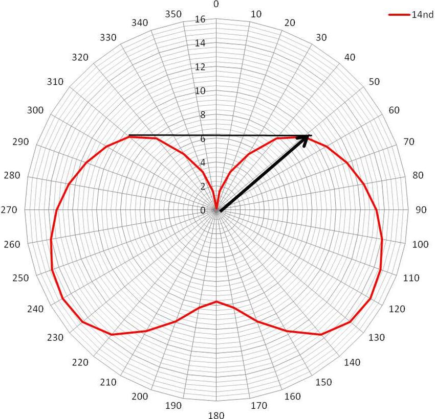
Contents
1. INTRODUCTION                                                                               3
2. THE TOPLINE NETWORK                                                                        3
3. THE PROCESSOR REGATTA                                                                      3
4. SYSTEM DESCRIPTION                                                                         5
5. INSTALLATION OF THE PROCESSOR REGATTA                                                      5
 5.1     INSTALLATION OF A BRAND NEW NKE SYSTEM                                                6
 5.2     INSTALLATION OF THE PROCESSOR REGATTA WITH AN EXISTING NKE SYSTEM                     6
 5.3     ADDING THE PROCESSOR REGATTA TO YOUR NKE SYSTEM                                       7
 5.4     ETHERNET CONFIGURATION                                                                8
 5.5     CONNECTING THE PROCESSOR REGATTA :                                                    8
 5.6     CONNECTION TO THE TOPLINE BUS                                                        10
 5.7     CONNECTOR NMEA1/COMPASS                                                              10
 5.8     NMEA 2 CONNECTOR                                                                     10
 5.9     NMEA INPUT                                                                           11
 5.10    NMEA SENTENCES INPUT PRIORITY RULES                                                  13
 5.11    NMEA OUTPUT                                                                          14
6. CONFIGURATION OF THE PROCESSOR REGATTA                                                     15
 6.1     CONFIGURE THE INSTALLATION FILE                                                      18
 6.2     CONFIGURE THE CONSTANTS CALIBRATION FILE                                             19
 6.3     CONFIGURE THE FILE VARIABLE.CSV                                                      20
7. ALGORITHM FOR THE PROCESSED FUNCTIONS                                                      21
 7.1     FUNCTIONS FOR BOAT MOTION                                                            21
 7.2     FUNCTIONS FOR BOAT SPEED                                                             22
 7.3     FUNCTION FOR WIND DATA                                                               23
8. CALIBRATING YOUR SYSTEM                                                                    24
 8.1    INTRODUCTION                                                                          24
 8.2    CALIBRATION ORDER                                                                     24
 8.3    CALIBRATING THE COMPASS                                                               25
 8.4    ROLL AND PITCH CALIBRATION                                                            25
 8.5    CALIBRATING BOAT SPEED                                                                25
   8.5.1    Linear boat speed response against boat’s heel angle                              26
 8.6    CALIBRATING FOR DRIFT                                                                 28
   8.6.1    Using a drift calibration adjustment value:                                       28
 8.7    CALIBRATING APPARENT W IND ANGLE                                                      28
 8.8    CALIBRATING TRUE WIND SPEED                                                           30
 8.9    CALIBRATING TRUE W IND ANGLE                                                          31
9. PERFORMANCE AND POLAR TABLES                                                               33
 9.1     READING A POLAR TABLE                                                                34
 9.2     READING A POLAR DIAGRAM                                                              35
 9.3     PERFORMANCE FUNCTIONS                                                                37
10.     ADDEDUM A                                                                             40
 10.1 CONFIGURING THE PC FOR THE FIRST CONNECTION TO THE PROCESSOR REGATTA                    40
   10.1.1 Connecting the Processor Regatta to the PC                                          40
   10.1.2 Configuring the network connection with Windows Seven                               40
   10.1.3 Configuring the network connection with Windows 10™                                 44
   10.1.4 Testing the connection with the Processor Regatta                                   47
11.     FREQUENTLY ASKED QUESTIONS                                                            48
12.     PROCESSOR REGATTA SOFTWARE EVOLUTION                                                  50

                                              2               47_processor_Regatta_um_UK_40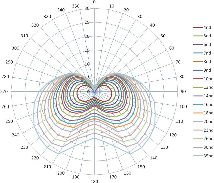
1. INTRODUCTION

Thank you for purchasing the nke Processor Regatta. This processor is the heart of the
system and provides the most accurate, dynamic and noise-free information to the
autopilot, the navigation programme, the tactician, the crew and of course the skipper.

In this manual you will find all the information necessary to:

-   Carry out Installation, configuration and calibration of the Processor Regatta and
    sensors
-   Access all the functions offered by the Processor Regatta
-   Get the best performance from your boat

2. THE TOPLINE NETWORK
The Topline system consists of sensors and displays networked with a single 3 wire cable
(shield: 0V, white: +12V, black: Data). Data is carried on the black “DATA” wire.
Displays have a variable address ranging from 1 to 20 while the sensors have a fixed
address with a value comprised between 21 and 210. The network is managed from one
of the displays that will be chosen as “MASTER” during the system commissioning. Its
address will be “1”.
Once turned on, the “MASTER” will scan all the addresses to discover all the displays and
sensors which are connected to the network.
Once the “MASTER” has scanned the network, it will ping only the channels it has
identified. Also, the “MASTER” will randomly ping the channel “0” (non identified display).
A specific answer from a display will generate an address for that display to integrate
dynamically the network.

3. THE PROCESSOR REGATTA

The Processor Regatta provides the following:

1. Performance:
   • Accurate measurement of wind speed and angle (true and apparent), boat speed,
     speed over ground, the boat movements, all with sensitivity to small changes.
   • Accurate measurement of acceleration and the boat’s attitude (magnetic heading,
     angles, acceleration, turn rates, magnetometric vector)
   • Accurate dynamic calculation of true wind as a result of the compensation of
     measured data from the masthead sensor, the geometry between the mast and the
     hull and the use of corrections table.

                                            3             47_processor_Regatta_um_UK_40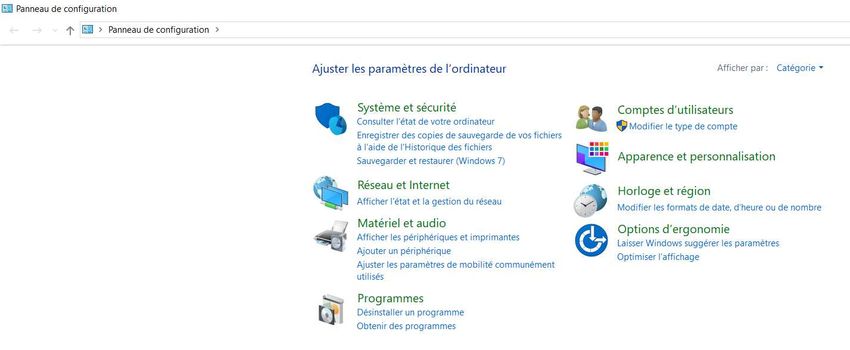
2. Fast data provision:
   • High speed data flow (fast reactivity to the measurements from sensors providing
     high speed updates to the autopilot and data display).
   • Fast data rate interface with the onboard PCs for the major navigation packages
     (via the SailNet protocol on IP and various gateways). Compatible with the Proteus
     communication system.

3. Safe and secure operation:
   • Integrated safety: various safe modes allow use of the main functions without the
     Processor Regatta.
   • The use of the lightest possible Linux OS ensures real time operation without
     background task (or virus) and avoiding mechanical moving parts (such as hard
     disk, fans…)
   • Auto diagnostic log for a good understanding in case of malfunction.

4. Standardisation :
    Simple and open formats and protocols specified for:
   • Variables logs
   • Variable exchange protocol via fast RS232/NMEA0183 or IP.
   • Adjustment for the linear calibrations, filtering, alarms and non-linear calibration
      files, polar tables.
   • Use of one single variable definition base for each level: in the remote Gyropilot
      Graphic display, the Processor Regatta, the variables log, the compatible
      navigation software (Deckman), the IP broadcast, the post-processing software
      (Excel..), the diagnostic software (Toplink ...).

5. Post-processing:
   • Internal communication for diagnostics and modeling.

6. Open data:
   • Functions can be customized or translated (display on the Gyropilot Graphic,
     Deckman, Tools).
   • Open IP protocol for « SailNet » variables exchange (Linux/windows libraries with
     samples supplied, possibility to use several boats and/or navigation programs
     simultaneously).

7. Upgrades:
   • Easy Processor Regatta update via IP
   • Use of the Topline peripherals with a Flash memory for onboard update with PC
     Toplink.
   • Processor Regatta interface page on the Gyropilot Graphic display for easy HCI
     update.

8. Power management:
   • Allows the on board PC to operate in standby mode while getting the performance
     data on the nke displays.
   • The Processor Regatta enhances the wind data (faster refresh and less noise). As
     a consequence, the autopilot steering is optimized and reduces the use of the ram’s
     motor.

                                         4            47_processor_Regatta_um_UK_40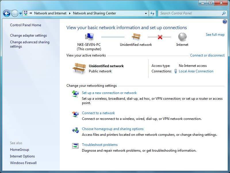
4. SYSTEM DESCRIPTION

               The equipment featured in this drawing is for indication only.
                         It does not reflect your own system.

5. INSTALLATION OF THE PROCESSOR REGATTA
In this chapter we will cover the installation of the unit and all calibration required in the
Topline network environment.

       IMPORTANT:
-   Please take time to read this manual carefully before you start installation

-   Any connection to the TOPLINE bus must be performed through the specific interface
    box # 90-60-417 and only with the TOPLINE bus cable # 20-61-001
-   Any work on the TOPLINE bus requires the system to be powered off.

                                           5              47_processor_Regatta_um_UK_40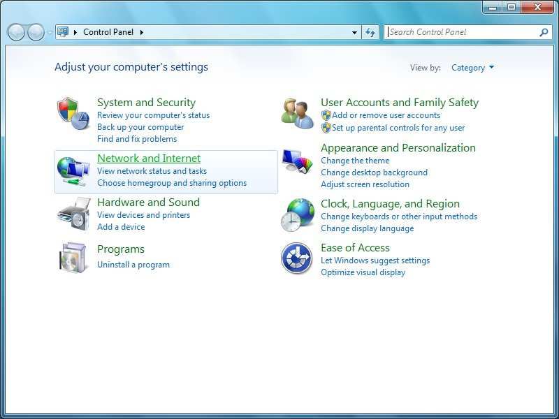
5.1 Installation of a brand new nke system

All units except the Processor Regatta must be installed first. Please refer to the manual
for each unit (sensors, displays…). We recommend using the Mutltigraphic or
Gyrographic as the system’s Master.
Once the system is installed, refer to “How to integrate Processor Regatta in an existing
nke system” to complete the installation.

5.2 Installation of the Processor Regatta with an existing nke system

As a first step, you need to update every component connected to the Topline network.
This is done with the « Toplink2 » software, or alternatively you can send the units to nke
customer support.

Firmware, database and the Toplink2 software (requires the Topline USB interface 90-60-
482) are all available for download at the following address: http://www.nke-marine-
electronics.com in the technical area (requires a password – access to trade only).

Table of compatibility with the Processor Regatta:

                                                               Minimum Version
  Type of unit                    Description
                                                                    required
Display           Multigraphic                                 All versions
Display           Multidisplay                                 All Versions
Display           Gyropilot Graphic                            V3.1
Display           TL25                                         V1.5
Display           Display and Pilot PAD                        All versions
Interface         Toplink 2                                    V2.0.11
Interface         Radio receiver                               V2.4
Interface         Wifi Box                                     All versions
Interface         Battery monitor 500                          All versions
Interface         Speed and depth Interface                    V2.0
Interface         Dual-speed and depth Interface               V2.0
Interface         Interface Loch for paddle wheel              V2.2
Interface         Interface sounder                            V2.2
Interface         Analog Monitor                               All versions
Interface         Analog Monitor 4X                            All Versions
Interface         Load Cell Monitor                            All Versions
Interface         Regatta Compass Interface                    V1.4
Sensor            Ultrasonic starboard / port                  V1.6
Sensor            Fluxgate compass                             N.C
Sensor            Carbowind HR                                 V1.8
Sensor            AG HR                                        V1.8
Sensor            9X Compass                                   All versions
Sensor            3D Sensor                                    V2 & V3
Sensor            HR 100 barometric sensor                     V1.0
Autopilot         Pilot processor                              V3.0

Once you have ensured that all units are up to date with a compatible version, you can
power the system on and check that it works properly. We strongly recommend choosing a

                                          6             47_processor_Regatta_um_UK_40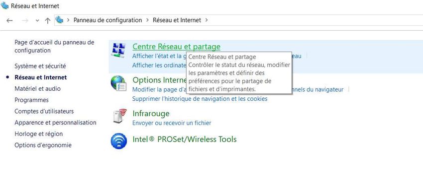
Multigraphic or Multidisplay as Master of the Topline network. This will make the
integration of the Processor Regatta easier to manage.

5.3 Adding the Processor Regatta to your nke system
When all the sensors, displays and interface units are up to date, compatible with the
Processor Regatta and fully working, you are ready to add the Processor Regatta to the
network. Once in place, it will become the Master. Therefore, the existing Master has to be
deleted so that the Topline network is clean of any Master.
You must reset the Multigraphic or Multidisplay master to assign it the 0 address. This
change of address is done in the menu, parameter, Maintenance, Topline address. See
the Multidisplay or Multigraphic manual to reset the Topline address.

          WARNING

The 3D sensor or Regatta Compass sensor must be connected to the « NMEA1
Compass » connector before connecting the PROCESSOR REGATTA (refer to the unit’s
manual). The PROCESSOR REGATTA will automatically detect those sensors (version
2.4 and up).
You must also connect the HF GPS if the version is lower than 2.2 or another GPS source
On the NMEA 2 input of the REGATTA PROCESSOR. In the case of a HF GPS version
2.2 or higher, it is not necessary to connect the NMEA 2 input. The Channels are
broadcast directly by Topline Bus by the antenna.

When powering the Topline network on, a blue LED situated on the front face of the
PROCESSOR REGATTA indicates the working status. The PROCESSOR REGATTA
always acts as the Master. When the system is powered on, the Master will create 2
« Lists ». Allow 30 seconds for boot completion.

     LED status                       Working status or fault description
      LED off          - Processor is powered off or faulty.
      Blue Led
    1 blip every 3     - Processor Regatta in normal working status
       seconds         - internal auto-check is correct
    ▲ 3s ▲
   100ms blip rate     - Processor Regatta is booting
  ▲▲▲▲▲▲▲
  1 blip per second    - The Processor has detected a serious error (lost a sensor,
  ▲ ▲ ▲ ▲              firmware version is not compatible...
      Fixed light      - Processor is out of work or booting.

Once the PROCESSOR REGATTA has started (Blue LED blips every 3 seconds), you
can give a new node number to the Multigraphic or Multidisplay which has been used
previously to check the system.
See the Multidisplay or Multigraphic manual to reset the Topline address.

                                          7             47_processor_Regatta_um_UK_40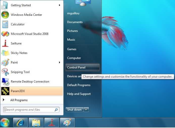
WARNING

The List creation is a long process (30 secondes). Always wait until the PROCESSOR
REGATTA boot is completed (blue LED = 1 blip every 3 seconds) before asking for a new
node number.

5.4 Ethernet configuration
Depending on the network configuration on board your boat, several connection options
are possible between your Processor Regatta and the PC.

    • Direct Ethernet connection:
The network cable is supplied with the Processor Regatta. It is a crossover cable that
allows direct connection to your PC.

                              RJ45 crossover network cable

   • Ethernet connection via a network:
The cable supplied with your Processor Regatta is a crossover cable. It allows
connection with the most recent Ethernet Switches. Please check your Ethernet Switch
compatibility with crossover cables. If not, you should use a straight-through cable.

5.5 Connecting the Processor Regatta :
Prior to connection, you must have configured your PC. The connection will operate via
ftp, http, and the Sailnet dll and will allow access to the calibrations tables, the log files
for trouble-shooting and software updating.

The default address of the Processor Regatta is 192.168.0.232 and the connection
credential is:
Login: root
Password: pass

                                           8             47_processor_Regatta_um_UK_40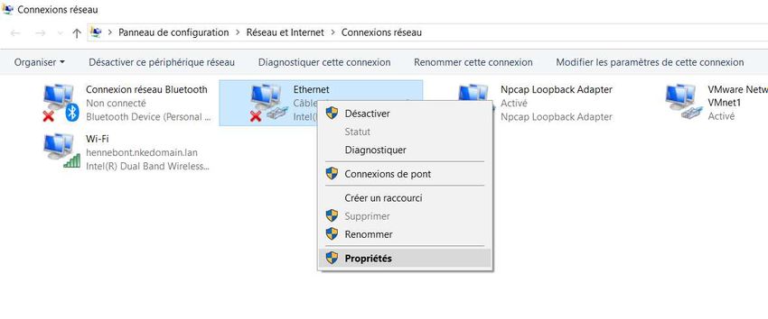
Please check the following points before any connection:
   • The blue LED indicates that the Processor Regatta works properly
   • On the Ethernet RJ45 on: yellow LED indicates activity / green LED indicates
      physical connection
   • Firewall: allow all ports for 192.168.0.232
   • If you use a Proxy: in the advanced connection settings of your web browser, add
      «192.168.0.232» in the section «not use Proxy for the addresses».
   • The HR processor does not manage DHCP server. If you use a point to point
      Ethernet and don’t have an IP address automatically attributed by DHCP, you
      should give your PC a fixed IP address such as 192.168.0.X where X is different
      from 232, which is the default address of the Processor Regatta. (see addendum
      A - Connecting the Pocessor Regatta)

With the http protocol:

Open your Internet browser (Internet explorer, Firefox etc.) and type in the address
http://192.168.0.232 in the address bar and press « Enter » or click on the connection
button to accept.

The Processor Regatta configuration page will appear.

With the FTP protocol :

To connect to the FTP server from your PC without having a user name and a password,
type in an Explorer window the address ftp://root:pass@192.168.0.232

In the above case Windows Explorer will ask for Login and Password.
Once entered they will be saved by Windows if you check “Save password”. In this case
you do not need to write root and pass in the ftp address.
ftp://192.168.0.232

                                        9               47_processor_Regatta_um_UK_40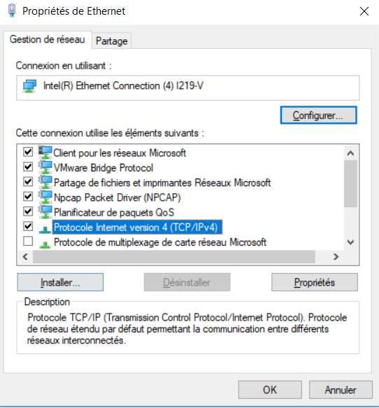
5.6 Connection to the Topline bus

The Processor Regatta features a Topline plug for connection to the Topline bus which
carries the 12 volts power supply as well.
Cable: twisted pair with aeronautical type shield.
Connector: Binder 5 pts série 620.

    Wire Colour              Function                     Termination
  Blue            Topline Data                        3 and 5 together
  White           +12V                                4
  Shield          Common                              1
  Not connected +5V OUT                               2

5.7 Connector NMEA1/Compass

Compass Regatta can be powered and communicate with this connector which can also
receive data from the 3D Sensor.

Cable: 3 wires + aeronautical type shield
Connector: Binder 5 pts series 620

   Wires Colour         Function            Termination
  Blue            TX Processor          5
  White           RX Processor          3
  Orange          +12V OUT              4
  Shield          Common                1

5.8 NMEA 2 connector

This connector can power and receive data from an NMEA device up to 115kb. Refer to
6.1 configure the installation file for the port configuration.
Cable: 3 wires + aeronautical type shield
Connector: Binder 5 pts series 620

                                                      Termination
    Wire colour             Function                                    Termination DB9pts
                                                         5pts
  Blue            TX Processor = RX NMEA 5                              2
  White           RX Processor = TX NMEA 3                              3
  Shield          Common                          1                     5
  Orange          +12V OUT                        4                     Isolate
  Not connected +5V OUT                           2                     Not connected

                                             10               47_processor_Regatta_um_UK_40
5.9 NMEA input
Below is the list of NMEA sentences accepted by the Processor Regatta
Each NMEA sentence matches with channels on the Topline bus
Channels are automatically detected. NMEA channels created by the Gyropilot Graphic
remain as priority input on the NMEA port of the Processor Regatta
Function
NMEA Code
number Possible Functions associated
64 Cross track error
APB 70 Autopilot status
71 Bearing Origin Waypoint to Destination Waypoint
BOD 71 Bearing Origin Waypoint to Destination Waypoint
62 Distance to waypoint
BWC
63 Bearing to waypoint
62 Distance to waypoint
BWR
63 Bearing to waypoint
76 speed of current
CUR
77 Direction of current
DBT 22 Depth
DPT 22 Depth
86 Latitude Degrees and Minutes
87 Latitude Minutes decimals
GGA
88 Longitude Degrees and Minutes
89 Longitude Minutes decimals
86 Latitude Degrees and Minutes
87 Latitude Minutes decimals
GLL
88 Longitude Degrees and Minutes
89 Longitude Minutes decimals
86 Latitude Degrees and Minutes
87 Latitude Minutes decimals
GNS
88 Longitude Degrees and Minutes
89 Longitude Minutes decimals
118 True Heading - geographical North
HDG
198 Magnetic Heading – Safe Mode
198 Magnetic Heading – Safe Mode
KVH 199 Heel Angle – Safe Mode
200 Trim Angle – Safe Mode
48 Air Temperature
MDA 49 Water Temperature
119 Barometric pressure – High resolution
MMB 119 Barometric pressure – High resolution
MTA 48 Air Temperature
MTW 49 Water Temperature
192 Apparent Wind Speed – High resolution
MWV
193 Apparent Wind Angle – High resolution
11 47_processor_Regatta_um_UK_4062 Distance to Waypoint
63 Bearing to Waypoint
RMB
64 Cross track error
67 VMG to Waypoint
27 UTC minutes and seconds
47 UTC Hour and day
69 UTC Year and month
86 Latitude Degrees and Minutes
RMC 87 Latitude Minutes decimals
88 Longitude Degrees and Minutes
89 Longitude Minutes decimals
208 Speed Over Ground
209 Heading Over Ground
ROT 207 Rate of turn and direction of turn.
21 Boat speed
42 Dead reckoned drift angle
VBW
208 Speed Over Ground
209 Heading Over Ground
76 Speed of Current
VDR
77 Direction of current
21 Boat speed
VHW
118 True Heading - geographical North
32 Log
VLW
31 Daily log
208 Speed Over Ground
VTG
209 Bearing Over Ground
192 Apparent Wind Speed – High resolution
VWR
193 Apparent Wind Angle – High resolution
WCV 67 VMG to Waypoint
64 Cross Track Error
XTE
70 Autopilot Status
XTR 64 Cross Track Error
27 UTC minutes and seconds
ZDA 47 UTC Hour and day
69 UTC Year and Month
62 Distance to Waypoint
ZDL_R
222 Time to Waypoint
225 Distance to Layline
ZDL_T
226 Time to Layline
12 47_processor_Regatta_um_UK_405.10 NMEA sentences input priority rules
A priority order is given to the data coming from the Topline bus on NMEA data.
NMEA sentences from the displays have a priority order on those coming from the
processor.
Each Function can be fed by several NMEA sentences. The table below indicates priority
between NMEA sentences.
Medium
Num Variable High Medium High Low
Low
21 Boat speed VBW VHW
22 Depth DPT DBT
27 UTC minutes and seconds ZDA RMC
32 Log VLW
31 Daily Log VLW
47 UTC Hour and day ZDA, RMC
48 Air Temperature MTA MDA
49 Water Temperature MTW MDA
62 Distance to Waypoint BWC RMB BWR ZDL_R
63 Bearing to Waypoint BWC RMB BWR
64 Cross Track Error RMB APB XTE XTR
67 VMG to Waypoint WCV RMB
69 UTC Year and Month ZDA RMC
70 Autopilot Status APB XTE
Bearing Origin Waypoint to
71 Destination Waypoint APB BOD
76 Speed of Current VDR
77 Direction of Currant VDR
86 Latitude Degrees and Minutes GNS GGA RMC GLL
87 Latitude Minutes decimals GNS GGA RMC GLL
88 Longitude Degrees and Minutes GNS GGA RMC GLL
89 Longitude Minutes decimals GNS GGA RMC GLL
118 True Heading – geographical North HDT HDG VHW
Barometric pressure – High
119 resolution MMB MDA
Apparent Wind Speed – High
192 resolution MWV VWR
Apparent Wind Angle – High
193 resolution MWV VWR
198 Magnetic Heading – Safe Mode KVH HDG
199 Heel Angle – Safe Mode KVH
200 Trim Angle – Safe Mode KVH
207 Rate of turn and direction of turn ROT
208 Speed Over Ground VBW RMC VTG
209 Course over Ground VBW RMC VTG
225 Distance to Layline ZDL_T
226 Time to Layline ZDL_T
222 Time to Waypoint ZDL_R
13 47_processor_Regatta_um_UK_405.11 NMEA output
Output frequency is linked to the baud rate selected.
The table below shows all NMEA sentences that can be output from the processor. An
NMEA sentence will be available for output if at least one value contained in the sentence
is used by the processor.
NMEA sentence Description
$INDBT … Depth below keel
$INDPT … Depth below keel
$INGGA … Global Positioning System Fix Data
$INGLL … Geographic position
$INHDG … Heading – Deviation and Variation
$INHDT … True heading
$INMTW … Sea Temp
$INMWV,x.x,R … Apparent Wind angle and speed
$INMWV,x.x,T … True Wind angle and speed
$INMWD … True Wind direction and speed
$INRMB … Recommended Minimum Navigation
$INRMC … Recommended Minimum GNSS Data
$INRSA … Rudder angle
$INVDR … Set and Drift
$INVHW … Water Speed and heading
$INVLW … Dual Ground/Water Distance
$INVPW … VMG
$INVTG … Course/Speed Over Ground
$INWCV … Waypoint closure velocity
$INXDR …,C,x.x,C,AIRT … Air Temperature
$INXDR …,P,x.x,B,BARO … Barometer
$INXDR …,N,x.x,N,FRST … Forestay
$INXDR …,A,x.x,D,ROLL … Heel angle
$INIXDR ...,H,x.x,P,HYGR … Humidity
$INXDR …,A,x.x,D,KEEL … Keel Angle
$INXDR …,A,x.x,D,LEEW … Leeway angle
$INXDR …,A,x.x,D,MAST … Mast angle
$INXTE … Cross track error, measured
$INZDA … UTC Time and Date
14 47_processor_Regatta_um_UK_406. CONFIGURATION OF THE PROCESSOR REGATTA
In this chapter we will cover the configuration of the Processor Regatta for your system.
You can access the Processor Regatta home page by typing this address in your Internet
browser: http://192.168.0.232 (refer to addendum A for PC configuration).
In this page several buttons link to the calibration tools.
Home Page: bring back to the home page.
15 47_processor_Regatta_um_UK_40Action: links to the Reboot and Stop buttons
Calibration: links to the true wind correction tables, boat speed correction tables, polar
tables and constants tuning.
16 47_processor_Regatta_um_UK_40Configuration: links to the Processor Regatta configuration.
Tools: links to various useful tools to get the best of the Processor Regatta.
17 47_processor_Regatta_um_UK_406.1 Configure the installation file
From the Processor Regatta home page press «configuration» to access the file
« Instal.ini ».
The path for this file is: ftp://root:pass@192.168.0.232/mnt/flash/processor/instal .
This file controls the configuration of your Processor Regatta. It contains two sections.
WARNING
The default configuration of this file is correct but you can apply modifications should
you want to customize your system.
Modifications are saved by pressing « Save File » and will be applied after you reboot
the Processor Regatta. This is done by pressing « Reboot » in the « Action » section.
[Language]
Language = 1 ; Gyropilot Graphic secondary language (0=French
1=English)
Performance = Y ; Performance calculus form polars Broadcasts the
performance data of the polar in processor memory on the Topline Bus.
Declination = Y ; Declination calculus Calculation of the declination from the table
in memory.
[Datalog]
ValidDatalog = Y ; Valid datalog (Y or N) Data recording on the USB stick.
[NMEA1]
ValidNmea1 = Y ; Valid NMEA1 Validates the input to which the compass is
connected. Automatic detection by default.
InstalNmea1 = 255 ; Type of compass sensor
; 7 = 3D Sensor
; 10 = Regatta Compass
; 11 = KVH Compass
; 13 = 3D Fusion
; 255 = AUTODETECT
BaudrateNmea1 = 4800 ; Baudrate of datas (if AUTOTEDECT is off)
[NMEA2] NMEA input output setting
ValidNmea2In = N ; Valid NMEA2 input (serial NMEA0183)
ValidNmea2Out = N ; Valid NMEA2 output (serial NMEA0183)
BaudrateNmea2 = 4800 ; baudrate NMEA183IN&OUT
[NMEAUdp] UDP input output setting
ValidUdpNmeaIn = N ; Valid NMEA183 input on UDP/IP
UdpNmeaInPort = 1001 ; UDP Port number for NMEA183 input on UDP/IP
ValidUdpNmeaOut= N ; Valid NMEA183 output on UDP/IP
UdpNmeaOutPort = 1000 ; UDP Port number for NMEA183 output on UDP/IP
UdpNmeaOutIP = 192.168.0.255 ; Recipient IP address (navigation PC)
(x.x.x.255 to broadcast)
[SailNet]
ValidSailNet = N ; Valid SailNet (IP variables synchronisation)
18 47_processor_Regatta_um_UK_40SailNetOutIP = 192.168.0.233 ; Recipient IP address (navigation PC)
SailNetOutPort = 4003 ; UDP Port number for SailNet output
SailNetInPort = 4004 ; UDP Port number for SailNet input
6.2 Configure the constants calibration file
Press « Calibration » on the Processor Regatta home page, and then on « Constants ».
It will give you access to the file « Calib.ini », which path is:
ftp://root:pass@192.168.0.232/mnt/flash/processor/constants .
Some constants, not accessible from a Multigraphic ou Multidisplay, can be adjusted
here.
[Constants];
HdgOff = 0.0 ; Offset cap additionnel (degrees)
Magnetic heading offset. It can be added to the one accessible from the Multigraphic or
Multidisplay. It is useful for adding an offset to the hundredth.
MastRotOff = 0.0 ; Offset angle de twist de mat (degrees)
Mast angle Offset. It can be added to the one accessible from the Multigraphic or
Multidisplay. It is useful for adding an offset to the hundredth.
MastDeflOff = 0.0 ; Offset Bascule/Deflection mat (degrees)
WindShear = 0.0 ; Cisaillement Vent Reel additionel(degrees)
Offset which compensates for the actual wind shear angle.
AWSOff = 0.0 ; Offset Vitesse Vent Apparent (noeuds)
Apparent wind speed Offset.
FailSafeBS = 6.0 ; Vitesse bateau secours (noeuds)
Boat speed taken into account in the event of loss of speedometer and speed over ground.
19 47_processor_Regatta_um_UK_40MeasLeewayOff = 0.0 ; Offset capteur de derive (degrees)
Offset of the drift sensor in degrees.
[MotionWindComp]
WindVaneHigh = 30.0 ; Hauteur Aerien/Centre Rotation avec gite (metres)
Height in meters of the wind sensor in relation to the center of rotation of the boat.
Coef1 = 6 Wind noise reduction coefficients configured for a sensor 3DV2,
Coef2 = 3 3DV3 and Quadrans. For KVH (Gyrotrack) use coefficients
Coef1 = 4, coef2 = 2.
6.3 Configure the file variable.csv
This file controls the way the functions are displayed on the Gyropilot Graphic and sets
them for export via the NMEA output port (NMEA2). It must be downloaded via the « ftp »
protocol at:
ftp://root:pass@192.168.0.232/mnt/flash/processor/SailNet/
Once modified and saved, it has to be uploaded to the same address in the Processor
Regatta. A « Reboot » will be required. This is performed from the home page by
pressing the “Action” button.
WARNING
We recommend keeping a copy of the file before doing any modification.
Num: id of the variable.
Help: English description of the variable.
En10Name: English name of variable.
En3Unit: Unit of variable (English).
Aide: French description of the variable.
Fr10Nom: French name of the variable.
Fr3Unit: Unit of variable (French).
View: toggle the variable display on Gyropilot Graphic. N = not displayed, Y = displayed.
Group: Name of the group of the variable.
ToplineDef: Name of the Topline variable. (Do not modify. For internal use only)
IntFormat: Format of the variable in the Topline bus and data log files. (Do not modify.
For internal use only)
FloatForm: Format of the variable in the Topline bus and data log files. (Do not modify.
For internal use only)
Zoom: Coefficient used to enhance data presence in data log files. (user can adjust this
value)
HzTopline: Definition of variables rate in Topline bus. (Do not modify. For internal use
only)
NmeaIN: This column indicates the NMEA sentences used by the NMEA input.
Custom: Gives authorization for a user’s variable coming from a NMEA input and a LUA
file.
20 47_processor_Regatta_um_UK_407. ALGORITHM FOR THE PROCESSED FUNCTIONS
This section describes the algorithms used to process the main functions used for the true
wind calculation and data for the autopilot. The following diagrams will help you
understand the system.
The following symbols will be used:
Manual
Apparent wind
Table of correction or
Sensor Mesurement
Or calculation speed Automatic
(MW_speedHR) Selection
Variable to display Variable
7.1 Functions for boat motion
Magnetic Declination
GPS 3D SENSOR HULL
File
Magnetic
Compensation
f
3DsensorMapper.exe
Magnetic
Declination Heading
(MagDecl) Compensation
Attitude calculation
Hull Trim Offset
Heel Offset
(OF_Gite)
(OF_Trim)
True Heading Hull Attitude
Pilot Magnetic Heading Measured Heel Angle Hull Pitch angle
Geographic North (3DH_Acc, 3DH_Gir,
(PilMagHdg) (MeasHeel) (3DH_Pitch)
(TrueHdgPil) 3DH_Mag)
25Hz 25Hz 25Hz 25Hz 25Hz
Heading Attitude, Heel, trim Heading Attitude, Heel, trim Heading Attitude, Heel, trim Heading Attitude, Heel, trim
Damping Damping Damping, Tangage Damping
(FI_Cap) (FI_Cap) (FI_Cap) (FI_Cap)
Cap Magnetic Heading True Heading Heel l _ Trim _
(MagHdg) (TrueHdg) (Heel) (Trim)
21 47_processor_Regatta_um_UK_407.2 Functions for boat speed
Port Ultrasonic Starbord Ultrasonic SOG Coefficient x AWS
CA_VitSuBa CA_VitSuTr
Port Surface Speed StarbordSurface Speed
Linear Calibration Linear Calibration
OF_VitSuBa OF_VitSuTr
Surface Speed Offset Surface Speed Offset
Port Starbord
PortUsBs StbdUsBs
2 Hz 2 Hz
Heel tack
selection AWA tack selection
Speed Calibration
According to the heel
BtSpdHeel.txt
Backup Selection
Boat Speed
_FI_VitSurf
Surface
Speed Damping
8 Hz
Surface Boat speed Surface Boat Speed pilot
(Boatspeed) (BtSpdPil)
22 47_processor_Regatta_um_UK_407.3 Function for wind data
Apparent wind speed Measured Mast Angle Apparent Wind Angle
Measured Heel Angle Hull Pitch angle
(MW_speedHR) (MesMastRot) (MeasHeel) (3DH_Pitch) (MW_angleHR)
25Hz 25Hz 25Hz 25Hz 25Hz
Attitude coque
(3DH_Acc, 3DH_Gir,
3DH_Mag)
Calculation of the 25Hz Calculation of the
dynamic compensation dynamic compensation
Height of the MHU to the
Apparent wind calculation Apparent wind calculation
Boat’s center of rotation
To a horizontal referential To a horizontal referential
Corrected Measured Boat Speed Corrected Measured
Wind Speed pilot Wind Angle
(CMWS) (BtSpdPil) (CMWA)
25Hz 8Hz 25Hz
True wind speed True wind angle
Calculation Calculation
Leeway Correction
(Leeway)
Uncorrected Uncorrected
True Wind Speed True Wind Angle
Course
(Orig_TWS) (Orig_AVR)
12.5Hz (Course) 12.5Hz
25Hz
True Wind Speed True Wind Angle
Table Table
True Wind Direction
(Adjvt.d) (Adjwa.d)
Calculation
WindShear
correction
Uncorrected (WindShear)
True Wind Direction
(Orig_TWD)
Apparent Wind Speed Apparent Wind Angle
12.5Hz
Retro Calculation Retro Calculation
12.5Hz 12.5Hz 12.5Hz 12.5Hz
True Wind Speed Apparent Wind Speed True Wind Angle Apparent Wind Angle True Wind Angle
Pilot pilote Table Pilot Pilote
(Adjwa.d)
(TWS_Pilot) (VVA_Pilote) (PilotAWA) (TWA_Pilot)
WindShear
PilotHR True Wind damping Apparent Wind Angle Damping Apparent Wind Angle Damping True Wind Angle Damping
correction
(TW_PilDamp) (FI_AVA1/ FI_AVA2) (FI_AVA1/ FI_AVA2) (TW_PilDamp)
(WindShear / Off_DVR)
True Wind Speed Apparent Wind Speed True Wind Direction Apparent Wind Angle True Wind Angle
(TW_Speed) (AW_speed) (TW_Dirn) (AW_angle) (TW_Angle)
23 47_processor_Regatta_um_UK_408. CALIBRATING YOUR SYSTEM
8.1 Introduction
Performance data is calculated and displayed using the polar table in the Processor
Regatta. It is important that wind, speed and compass sensors are correctly calibrated to
achieve accurate data for true wind direction and speed, target boat speed, VMG...
Wrong calibration may cause mistakes in tactical decisions.
8.2 Calibration order
Prior to typing values in the true wind angle table, all calibrations for the primary sensors
must have been achieved:
• Compass
• Speed sensors
• Wind sensors
We recommend processing the calibrations in the following order:
24 47_processor_Regatta_um_UK_408.3 Calibrating the compass
Please refer to the calibration section in the sensor’s manual.
8.4 Roll and pitch calibration
The calibration of these parameters can be achieved using a digital or laser level. Place
the level on the reference surface indicated by the architect. The 3D Sensor or Compass
Regatta must be free from any heavy metal presence such as a pontoon or a cargo ship
within a 20 meters radius. The boat must be well balanced. Check that the weight
distribution is normal on board. Ideally, the boat should be empty of all sails, anchors,
safety equipment, food, etc… Run this operation in calm water.
The calibration values will be typed in the following Multigraphic or Multidisplay menu:
Menu ► Sensors ►Heel angle ►Offset
Menu ► Sensors ►Trim angle ►Offset
8.5 Calibrating boat speed
Boat speed is measured in the boundary layer which varies from one boat to another.
Paddlewheel sensors measure boat speed inside a disrupted and accelerated water flow.
The measurement is not linear and the resulting error may vary against the heel angle.
The water speed measurement by ultrasonic speed sensors is about ten centimetres away
from the hull. The water flow is much less disrupted and the measure is linear.
Nevertheless, these measurements tend to be 1 or 2% optimistic when the boat is strongly
heeling. This is due to the growth of the boundary limit and the calibration being made with
the boat not heeling.
Calibration can be done in two different ways:
Consecutive runs on a given course:
With this method you need to choose a course with known distance, for example between
two buoys. Reset the log at the starting point, and motor between the two points. Note the
log once reaching the second point. Repeat the run in the opposite way, and note again
the log’s value.
Example:
Run 1: measured log 1,05
Run 2: measured log 1,09
The true distance between the two buoys is 0.97 miles.
0.97
Run 1: = 0.92
1.05
0.97
Run 2: = 0.88
1.09
25 47_processor_Regatta_um_UK_400.88 + 0.92
The calibration adjustment is: = 0 .9
2
Calibration using SOG as the reference:
With this method you need to motor at ten knots on two consecutive runs at opposite
headings (in order to eliminate the effect of the current). Both runs must be of equivalent
distance. SOG from the GPS will be the reference speed. The calibration adjustment will
be the result from averaged boat speed and averaged Speed Over Ground.
The calibration adjustment value can be calculated from the data logged in the internal
USB key. Useful data will be extracted for use with the formula below. Navigation software
which features a boat speed calibration tool can also be used.
Useful tip:
If the boat’s system has two ultrasonic sensors connected to an Interface Dual, you can
proceed as follows:
The calibration adjustment value will be entered for each sensor by identifying the correct
side and by forcing the heel with an offset greater than 3° for each. Heel values are
negative on the Multigraphic or Multidisplay for a starboard side heel.
Menu ► Sensors ►Boat speed ►Calibration
8.5.1 Linear boat speed response against boat’s heel angle
Modern monohull designs such as the Open 60, with flat bottoms and a hard chine, have
a wetted area where the longitudinal axis is different when heeling (such as a catamaran
with asymmetric hulls). Therefore the speed sensor cannot be aligned correctly when the
boat is flat or heeling. You may have to adjust the boat speed against the heel angle.
For that purpose, a table « BtSpdHeel.txt » is available in the Processor Regatta at the
following address: ftp://root:pass@192.168.0.232/mnt/flash/processor/tables
It can also be accessed from the home page by pressing the « Calibration » button, and
further the « Boat Speed vs Heel » button.
26 47_processor_Regatta_um_UK_40Heel BsCal
-40.0 0.960
-25.0 0.980
-10.0 0.990
0.0 1.000
10.0 0.990
25.0 0.980
40.0 0.960
Apply the same method as described for the boat speed calibration adjustment for each
heel angle (several runs at constant speed and heel angle). Enter the values in the
« BsCal » of the table.
WARNING
Always save the modifications by pressing « Save File ». Once the file has been saved,
you must reboot the Processor Regatta for the changes to be taken in account. This is
done by pressing « Reboot » accessible from the « Action » section.
27 47_processor_Regatta_um_UK_408.6 Calibrating for drift
Drift angle is not easy to evaluate, calculate or measure. It is linked to the hull shape, the
design and presence of centerboards, foils, canting keel… Current is also a factor to
consider.
The drift angle is determined between the longitudinal axis of the boat and the progression
vector over the water surface. The issue being that the boat progresses on the longitudinal
axis of the wetted area, which makes an angle with the longitudinal axis of the boat when
heeling.
There are two methods to adjust the calibration for drift.
8.6.1 Using a drift calibration adjustment value:
This value is found on the Multigraphic or Multidisplay
Menu ► Sensor ► Leeway angle ►Calibration
The drift formula is as below:
Where drift unit is degrees, heel angle unit is degrees, boat speed unit is knots and drift
will be °/nd². Drift adjustment is a global value applying to any navigation conditions. You
can either use an average value for any conditions or change that value for each wind
force. The drift angle against boat speed and heel angle can be found in the polar provided
by the architect. The drift adjustment values can be recalculated with the formula below,
and averaged.
8.7 Calibrating Apparent Wind Angle
Calibrating the Apparent Wind Angle will adjust the mast alignment error and apply
corrections for the wind shear effects.
This can be done only if the rig (backstays, headstay, kicker…) and sail tuning is
absolutely identical on port and starboard whilst sailing and carrying out the calibration.
The helmsman must keep focused on the telltales and completely ignore any information
coming from electronic instruments to avoid influences. Boat speed and heel must also be
identical from one side to the other. Set the correct sails for the weather conditions. We
recommend at least four legs are sailed in order to compare the readings and determine
an offset value to apply.
Inhibit the true wind correction table and reset the wind shear adjustment value. This can
be done from the home page by pressing on the « Calibration » button, and then choose
« Constants » (refer to § 6.2).
28 47_processor_Regatta_um_UK_40To measure the Apparent Wind Angle you can use the tools of performance software or
achieve the calculation on your own using the data logged on the USB key embedded in
the Processor Regatta, or alternatively use the application of the Gyropilot Graphic.
Warning! If you work with software such as « Tactique » from Adrena, the offset is
calculated from the function « Apparent Wind Angle ». This function is reverse calculated
from the true wind angle and damped for display. Therefore the true wind table needs to
be reset as well as the wind shear and you have to apply the offset to the existing value if
different from 0.
The l nke calibration wizard uses the raw data
AWA -24° AWA 27°
Apply the offset with the Multigraphic or Multidisplay :
Page ► Sensors ►App wind angle ► Offset
AWA port > AWA starbord :
Add half the difference between the two values
If AWA port < AWA starboard:
Substract half the difference between the two values
29 47_processor_Regatta_um_UK_408.8 Calibrating true wind speed
Even placed a meter away from the mast head on top of a carbon arm, the measure made
by the aerial sensor may suffer from disruption. When sailing downwind, the mainsail
creates an acceleration of the wind. Heel angle also has an influence on wind speed
measurement. For all these reasons we recommend calibrating for wind speed.
The correction table « Adjvt.d » is available in the Processor Regatta at the following
address: ftp://root:pass@192.168.0.232/mnt/flash/processor/tables
It can also be accessed from the home page by pressing the « Calibration » button, and
further the « True Wind Speed » button.
If the table is already filled with values, the corrections will have to be added to the existing
values.
Measurement procedure:
First, place the boat upwind and average the value read for wind speed.
Then, measurements have to be made in various wind strengths ranging from 5 to 30
knots. It is a continuous process. Note the wind speed values as you sail upwind, reaching
and downwind. You may find it useful to populate the correction table with the results from
averaging these values.
An example of the wind speed correction table is shown below. The column on the left
shows the wind speed. For each wind speed there are correction factors at various wind
angles, where V is the correction (in knots) and A is the wind angle (in degrees).
30 47_processor_Regatta_um_UK_40v1 a1 v2 a2 v3 a3
5.0 0.0 44 -0.3 93 -0.6 141
10.0 0.0 38 -0.6 96 -1.2 153
15.0 0.0 36 -0.9 95 -1.8 154
20.0 0.0 37 -1.2 93 -2.4 148
25.0 0.0 39 -1.5 96 -3.0 152
30.0 0.0 41 -1.8 98 -3.6 155
35.0 0.0 42 -2.1 100 -4.2 158
50.0 0.0 42 -3.0 100 -6.0 158
IMPORTANT
This is a very sensitive table and we recommend you use with the highest care.
Always save the modifications by pressing « Save File ». Once the file has been saved,
you must reboot the Processor Regatta for the changes to be taken in account. This is
done by pressing « Reboot » accessible from the « Action » section.
8.9 Calibrating True Wind Angle
The True Wind Angle table allows correction of the True Wind Angle without exploring the
causes of the angles discrepancies. This method is a global correction of all repeatable
errors (twist, flow acceleration downwind, sensor).
To complete the true wind calibration, it is necessary to tack often and record the True
Wind Direction values. We recommend running these measures with a fairly stable wind,
on several navigation sessions with wind speed ranging from 5 to 30 knots.
Tribord amure Bâbord amure
TWD 250° TWD 260°
Compas 210° Compas 300°
10°
45° 45°
31 47_processor_Regatta_um_UK_40TWD port > TWD starbord :
Add hald of the difference between both values.
For this purpose a correction table « Adjwa.d » is available at the following address in the
Processor Regatta:
ftp://root:pass@192.168.0.232/mnt/flash/processor/tables ,
Alternatively, you can access that table from the home page under « Calibration » and
then « True Wind Angle ».
If the table already contains values, the corrections will be added to the existing entries.
The table below is a True Wind Angle correction example. The column on the left shows
true wind speed in knots. V1 is the correction in degrees. A1 is the angle for which the
correction is applied. Same for V2 and A2 (reaching) ; and V3 and A3 (downwind).
32 47_processor_Regatta_um_UK_40v1 a1 v2 a2 v3 a3
0.0 -7.0 44 -2.0 93 4.0 141
5.0 -7.0 44 -2.0 93 4.0 141
10.0 -3.0 38 -1.0 96 3.0 153
15.0 -2.5 36 0.0 95 1.0 154
20.0 4.5 37 1.0 93 -1.0 148
25.0 6.5 39 1.0 96 -1.0 152
30.0 8.0 41 1.5 98 -2.0 155
35.0 8.0 42 1.5 100 -2.0 158
50.0 8.0 42 1.5 100 -2.0 158
WARNING
Always save the modifications by pressing « Save File ». Once the file has been saved,
you must reboot the Processor Regatta for the changes to be taken in account. This is
done by pressing « Reboot » accessible from the « Action » section.
9. PERFORMANCE AND POLAR TABLES
To optimize the boats performance it is essential to constantly understand the theorical
optimum speed of the boat against the wind speed and angle. The target boat speed is a
guide to fine tuning the sails and determining the optimum wind angle upwind as well as
downwind.
The polar table enables you to display the « Performance » functions. It can be loaded in
the Processor Regatta via a ftp link or the nke calibration wizard.
Polar tables are supplied by the architect or the boat builder. You can build your own by
recording the boat speed against wind angle for each wind speed.
The polar table is stored in the « Processor Regatta » at the following address:
ftp://root:pass@192.168.0.232/mnt/flash/processor/Tables/SpeedPolar.pol
Alternatively, you can access that table from the home page under « Calibration » and
then « Boat Speed Polar ».
33 47_processor_Regatta_um_UK_40A default polar table is stored in the Processor Regatta. It needs to be updated for your
boat.
WARNING
Always save the modifications by pressing « Save File ». Once the file has been saved,
you must reboot the Processor Regatta for the changes to be taken in account. This is
done by pressing « Reboot » accessible from the « Action » section.
9.1 Reading a polar table
The table below is an example of a polar table in the Processor Regatta. The index on
the top line shows the true wind speed in knots. The column on left shows the true wind
angles in degrees. Boat speeds are in knots.
34 47_processor_Regatta_um_UK_40TWA 4 6 8 10 12 14 16 20 25 30
33 2.761 4.076 5.08 5.624 5.904 6.044 6.107 6.104 5.84 5.176
36 3.043 4.448 5.475 5.975 6.23 6.354 6.422 6.446 6.28 5.802
39 3.302 4.782 5.806 6.259 6.477 6.587 6.654 6.694 6.594 6.277
50 4.07 5.688 6.572 6.882 7.052 7.172 7.26 7.361 7.368 7.256
60 4.541 6.156 6.918 7.251 7.437 7.581 7.695 7.85 7.932 7.899
70 4.821 6.383 7.107 7.542 7.762 7.942 8.101 8.352 8.534 8.583
80 4.925 6.456 7.206 7.708 8.063 8.308 8.524 8.876 9.223 9.434
90 4.974 6.664 7.422 7.796 8.253 8.662 8.949 9.526 10.134 10.566
105 5.055 6.682 7.495 8.106 8.559 8.962 9.404 10.567 11.631 12.578
120 4.695 6.456 7.339 7.943 8.679 9.454 10.104 11.327 13.237 15.149
135 4.085 5.849 6.926 7.676 8.433 9.235 10.102 12.202 14.791 17.174
140 3.805 5.538 6.723 7.491 8.213 9.048 10.07 11.912 15.335 17.898
150 3.246 4.833 6.166 7.019 7.683 8.373 9.187 11.582 15.493 18.583
165 2.494 3.77 4.988 6.076 6.876 7.511 8.122 9.662 12.464 16.247
The polar table file has the « .pol » extension. The maximum format is 32 lines for 17
columns, tabulation separator and point decimal sign.
If that format is not followed, an error message will appear in the log file of the Regatta
Processor.
9.2 Reading a polar diagram
The diagram below shows both sides, but usually, only the port side is shown, as both
tacks should be same.
The boat line is vertical, with the bow on the top. The radiuses feature the true wind angle.
Each curve represents the boat speed for a given wind speed.
35 47_processor_Regatta_um_UK_40The diagram shows the target boat speed against wind speed and wind angle.
As shown on the picture below, a target boat speed upwind is determined with a line
perpendicular to the boat speed axis and tangential to the highest point of the curve.
36 47_processor_Regatta_um_UK_409.3 Performance functions
The Processor Regatta generates performance functions from the polar table. They are
displayed on the following nke displays:
Multigraphic
Multidisplay
These functionss are a guide for fine tuning. Displaying these data in real time gives
information about boat speed and wind angle against the target (theoretical values)..
• VMG :
Stands for Velocity Made Good.
It is the component of velocity that is in the direction of the mark, should it be
upwind or downwind. In the case of sailing upwind, it is actually the speed towards
the wind. It is a useful indication
37 47_processor_Regatta_um_UK_40Wind
VMG = boat speed Xcosine (True Wind Angle)
VMG
• CMG :
Stands for Course Made Good.
It is the speed towards the mark.
.
Upwind and downwind it is not very relevant, while sailing reaching it is a very
valuable data.
Route CMG = Boat speed * cosine (Heading - Marks
bearing)
Wind Tangent point to polar
CMG
• Target boat speed:
It is the theoretical best VMG. Useful information when sailing downwind or upwind.
For other conditions it is better to use the polar speed.
• Target true wind angle :
It is the optimum wind angle for a given wind speed. This angle gives the best VMG
• Polar speed :
This function is calculated from the polar table against the wind speed and wind
angle. It shows the optimum speed for the wind conditions.
38 47_processor_Regatta_um_UK_40• % target boat speed :
It is the ratio between the actual boat speed and the target boat speed
• % Polar speed :
• It is the ratio between the actual boat speed and the polar boat speed
•
• Angle error VMG :
It is the error between the actual wind angle in degrees and the angle at VMG.
• Angle error CMG :
It is the error between the actual wind angle in degrees and the angle at CMG.
• % target VMG:
It is the ratio between the component of the velocity towards the wind and the target
VMG
• % target CMG :
• It is the ratio between the component of the velocity towards the wind and the target
CMG
.
39 47_processor_Regatta_um_UK_4010. ADDEDUM A
10.1 Configuring the PC for the first connection to the Processor Regatta
10.1.1 Connecting the Processor Regatta to the PC
Connect the Processor Regatta to your PC with the crossover cable
10.1.2 Configuring the network connection with Windows Seven
Set a local fixed IP for your PC:
Open the control panel from the start menu
40 47_processor_Regatta_um_UK_40Click on « View Network status and tasks»
41 47_processor_Regatta_um_UK_40On the right side, click on « Local area Connection »:
(or the connection used for the Processor Regatta).
Click on Local area Connection and choose Properties.
42 47_processor_Regatta_um_UK_40Double-click on Internet Protocol version 4 (TCP/IPv4). Tick the box, use the following IP
address and enter 192.168.0.233 ((where 233 can be replaced by any number between 2
et 254, except 232), and Subnet Mask = 255.255.255.0
Click OK.
43 47_processor_Regatta_um_UK_4010.1.3 Configuring the network connection with Windows 10™
Here, the computer and the HR Processor are networked by an RJ-45 cable.
They each have an IP address that allows them to communicate with each other. The local
network IP address can be fixed or dynamic. Since neither your computer nor the
processor has a DHCP server allowing dynamic addresses to be delivered, your
connection will be in fixed IP.
The first task is to define a fixed local IP address on the PC concerned. To get started,
type control panel, then ENTER.
Click on the link "network and Internet"
44 47_processor_Regatta_um_UK_40Select the "network and sharing center"
Click on "modify the card parameters"
On Ethernet card, right click and "Properties"
45 47_processor_Regatta_um_UK_40Double-click on the “Internet Protocol version 4 (TCP / IPv4)”
A new window appears. Check Use the following IP address. IP address put
192.168.0.233 * (you can replace 233 with any number between 2 and 254, except 232),
at Subnet mask enter 255.255.255.0
* By default, the Processor HR is configured to work with a PC at this address. Click on
OK to validate.
46 47_processor_Regatta_um_UK_4010.1.4 Testing the connection with the Processor Regatta
We shall run a PING command to check the connection.
Start \ Programs \ Accessories \ Run
The following window opens:
Enter cmd and clic OK. A DOS prompt will open in which you type ping 192.168.0.232
The Processor Regatta is now connected
47 47_processor_Regatta_um_UK_4011. FREQUENTLY ASKED QUESTIONS
1. Message on Gyropilot Graphic « Trop d’erreur sur le bus » or on Multigraphic,
Multidisplay « Bus en collision »
There may be a conflict between addresses on the Topline bus. Disconnect the
Processor and check each node address. Make sure there is no master on the bus.
You should see the message « Master missing» on each display. Then reconnect the
Processor.
2. Message on display « Maitre absent»
There is no Master. Check the data wire connections.
3. No deviation and / or the time is different from UTC
The deviation value is 0. Check the deviation on local official charts or navigation aids.
The deviation is a calculated value resulting from GPS data. Check that the Processor
receives all GPS data correctly and particularly that the status of position in the
GPGLL sentence is « A » (valid data)
4. The control led flashes once per second
Error mode. Disconnect all the elements from the bus, leaving only the Processor.
Power off the system again. If the led keeps on flashing, contact your dealer.
5. Boat speed shows « panne »
The Ultrasonic speed sensor cannot read flow (happens when the boat does not
move). In the event that boat speed is not available, the wind data will be calculated
using over ground speed if available on the bus. If not, a boat speed will be simulated
(see 6.3 « FAIL SAFE BS »).
6. No compass data
This data comes from the Topline compass or from the 3D Sensor. Check the sensor’s
parameters (see the sensors manual).
7. No True Wind data
Running safe mode, if the apparent wind data are correct, check boat speed. If boat
speed is correct reset the true wind calibration.
8. Message on Gyropilot Graphic « Défaut capteur 59 178 »
Apparent wind damping is over 32. Change it to a better value.
9. The Gyropilot Graphic does not accept a node address
With the Processor connect the Gyropilot Graphic on the Topline bus with the address
0. If it rejects the address given by the Processor and automatically turns Master, there
is a Topline bus reading error. Check errors in the log file. If there is no Topline bus
error, the file mvn.cfg is probably broken
10. Is it possible to export log files while the pilot is on?
In theory, yes. But this requires all the Processor’s resources. Therefore, the
Processor may slow down and this would disrupt the autopilot. To avoid any risk, we
recommend not doing this operation while the pilot is on.
48 47_processor_Regatta_um_UK_4011. Target boat speed function displays erratic values such as 300%...
The polar file is corrupted. Check the format (see 9.2 Reading a polar )
12. I cannot download the new firmware with Toplink
Downloading the firmware with toplink requires disconnecting the Processor Regatta
13. The Gyrographics display sounds continuously for 30 seconds when powered
on
Critical data is missing. It could be boat speed, speed over ground, wind data or
compass data.
49 47_processor_Regatta_um_UK_4012. PROCESSOR REGATTA SOFTWARE EVOLUTION
REV Date Information
V1.9 30/03/2010 - Addition of the True heading and True true wind direction channels
V2.0 - Calculation of the direction of the bottom wind
- Calculation of bottom wind speed
- Auto-detection of 3D hull sensor (V1, V2, Compas Regatta, KVH)
- Management of offsets in CAP MAG2 emergency magnetic heading mode
(KVH or NMEA)
- Addition of the autocompensation function of the Regatta compass
- Added management of offset heading, list and pitch in the Regatta
compass
- Added heading, heel and pitch filtering in the Regatta compass
V2.1 - Bug fixes
V2.2 - Modification Management of degraded water speed mode. If US speedo
not hooked, calculation on speed over ground and “Pan” display.
- Authentication of the elements of the bus when the list is created. If the
firmware is not up to date, the Processor does not start.
- Modification of the management of the blue control led
V2.3 - Limitation of heel angle calculation to a maximum of 60 °
- Limitation of the pitch angle calculation to a maximum of 40 °
- Added error message when 3DH data is outliers
V2.4 12/07/2011 - Compatibility with Topline GPS
V2.5 15/10/2012 - Compatibility with the latest 3DH V2 firmware
- Correction of sign error on pitch
- Addition of the Graphic Multifunction authentication
V2.6 - Correction of the loss of an NMEA source after a timeout (example during a
GPS stall)
V2.7 - Addition of identifiers of wifi interfaces
- Quick scan of the Multifunction graphic for the pilot
V3.2 28/10/2013 - Fixed a bug on wind noise reduction.
- Wind noise reduction coefficients, to be set in "Constants" according to the
compass sensor:
V3.7 14/09/2015 - Compatibility with 3D Fusion
- Fixed Processor crash when NMEA baudrate is incorrectly configured
- Not compatible with Sailtune V2.1
V3.9 12/09/2016 - Compatibility with 3D sensor V3
- Compensation available from the processor web page (for 3D Sensor V3)
- Compatibility with Loch paddle wheel
V4.0 07/02/2019 - Compatibility with Multidisplay and Pad
- Compatibility with the latest 3D Sensor V3 in automatic detection
50 47_processor_Regatta_um_UK_40You can also read