PD-96XXG - Microchip Technology
←
→
Page content transcription
If your browser does not render page correctly, please read the page content below
PD-96XXG
                  PD-96XXG PoE Multiport Series User Guide

Introduction
Microchip’s family of Power over Ethernet (PoE) Midspans PD-96xxG series inject power over data-carrying Ethernet
cabling. Employing these devices reduces the need for AC outlets, local UPS, and AC/DC adapters near Powered
Devices (PDs).
PD-9606G/9612G Midspans support 6 and 12 ports in a 10/100/1000BaseTx Ethernet network respectively, over
TIA/EIA-568 category 5/5e/6 cabling. The PD-96xxG family series can provide up to 95W according to the HDBaseT
PoE standard. These PD-96xxG series implements a Twin High (TH) PSE system, delivering 47.5W over 2 pairs
(total 95W). DC power is supplied over both spare and data pairs of wires within a cable (1/2, 3/6, 4/5, and 7/8) to
terminal units.
PoE Midspan powers devices that are PoE enabled or equipped to receive PoE. These devices are called PDs.
PoE Midspans offer the following key features:
 • Safe and reliable power over an existing Ethernet infrastructure.
 • Remote management using web control and/or SNMPv3.
 • High-level of network security.
 • Safe solution that protects network infrastructure.
                                         ®
 • Standards compliant: PoH and IEEE 802.3at.
 • Provides safe Power and Data over a single RJ45 cable.

© 2021 Microchip Technology Inc.                        User Guide                                DS00004055A-page 1
and its subsidiaries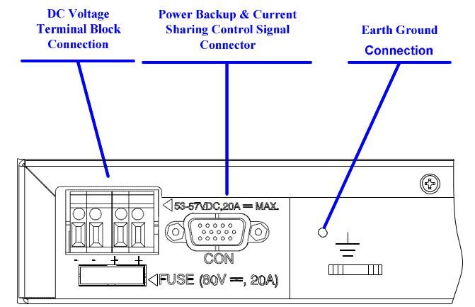
PD-96XXG

Table of Contents
Introduction.....................................................................................................................................................1

1.    Standards and Safety Guidelines............................................................................................................4
      1.1.       Part Number Definition................................................................................................................. 4
      1.2.       Electrical Compatibility Approvals................................................................................................ 4
      1.3.       Safety Standard Approvals...........................................................................................................4
      1.4.       CE Marking...................................................................................................................................4
      1.5.       Safety Information........................................................................................................................ 4

2.    Information en Matière de Sécurité......................................................................................................... 6
      2.1.       Directives Générales.................................................................................................................... 6
      2.2.       Mises en Garde............................................................................................................................ 6

3.    10/100/1000Base-TX Ports Definition.....................................................................................................7
      3.1.       Data Input Ports........................................................................................................................... 7
      3.2.       Data and Power Output Ports...................................................................................................... 7
      3.3.       Indicators......................................................................................................................................7
      3.4.       Connectors................................................................................................................................... 9

4.    PoE Midspan Installation.......................................................................................................................10
      4.1.       Background Information............................................................................................................. 10
      4.2.       Verifying Kit Contents................................................................................................................. 10
      4.3.       Rack Mounting Brackets.............................................................................................................11
      4.4.       Installation Factors..................................................................................................................... 11
      4.5.       Connecting Ethernet Cables.......................................................................................................11
      4.6.       Connecting Power Cables.......................................................................................................... 11
      4.7.       Powering Up the Unit................................................................................................................. 12

5.    Troubleshooting.....................................................................................................................................13
      5.1.       Preliminary Steps....................................................................................................................... 13
      5.2.       Troubleshooting Steps................................................................................................................13

6.    Specifications........................................................................................................................................ 14
      6.1.       Physical Specifications...............................................................................................................14
      6.2.       Environmental Specifications..................................................................................................... 14
      6.3.       Electrical Specifications..............................................................................................................14

7.    Microchip’s PowerView Pro...................................................................................................................15

8.    Power Backup and Power Redundancy Connection............................................................................ 16
      8.1.       Power Backup............................................................................................................................ 16
      8.2.       Power Redundancy.................................................................................................................... 16
      8.3.       Connectors................................................................................................................................. 16
      8.4.       Connecting Backup and Redundancy Connectors.....................................................................17
      8.5.       Power Backup and Power Redundancy Indications...................................................................19

9.    Contacting Technical Support............................................................................................................... 20

© 2021 Microchip Technology Inc.                                                     User Guide                                                      DS00004055A-page 2
and its subsidiaries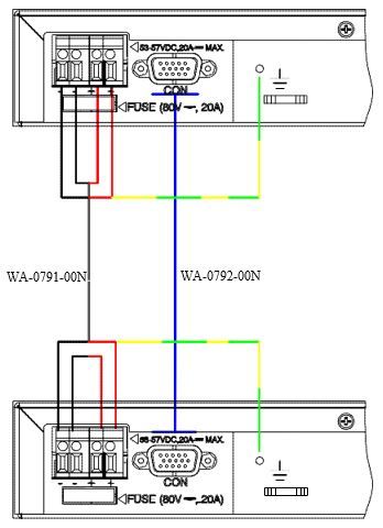
PD-96XXG

10. Revision History.................................................................................................................................... 21

The Microchip Website.................................................................................................................................22

Product Change Notification Service............................................................................................................22

Customer Support........................................................................................................................................ 22

Microchip Devices Code Protection Feature................................................................................................ 22

Legal Notice................................................................................................................................................. 23

Trademarks.................................................................................................................................................. 23

Quality Management System....................................................................................................................... 24

Worldwide Sales and Service.......................................................................................................................25

© 2021 Microchip Technology Inc.                                                    User Guide                                                     DS00004055A-page 3
and its subsidiaries
PD-96XXG
                                                                                 Standards and Safety Guidelines

1.      Standards and Safety Guidelines
        The following sections mention the standard and safety guidelines for the product.

1.1     Part Number Definition
        PD-96xxG/ACDC/M: 4–pairs AC and DC input family.
        Table 1-1. Part Number Definition

         Symbol                        Description
         xx                            Represents number of ports (6 or 12).
         AC                            Midspan has AC input.
         DC                            Midspan has DC input, current sharing, and power backup features between two
                                       Midspans.
         M                             Midspan includes PowerView Pro (See 7. Microchip’s PowerView Pro).

1.2     Electrical Compatibility Approvals
        Microchip’s PD-96xxG series complies with the following standards:
         • FCC Part 15: Class UTP cabling
         • EN 55032: Class B with UTP cabling
         • EN 55024 (CISPR 24)
         • Canadian ICES-003, Class B

1.3     Safety Standard Approvals
        Microchip meets the following safety standards. Consult Microchip for a complete list of safety certifications.
         • UL/IEC/EN 62368-1

1.4     CE Marking
        CE marking on this product indicates that this product complies with the Electromagnetic Compatibility (EMC)
        Directive and Low Voltage Directive (LVD).

1.5     Safety Information
        Read the safety information before using the PoE Midspan unit.

1.5.1   General Guidelines
        Read the following safety information before carrying out any installation, removal, or maintenance procedure on the
        PoE Midspan. Warnings contain directions to be followed for the safety of personal and product.

        © 2021 Microchip Technology Inc.                          User Guide                                 DS00004055A-page 4
        and its subsidiaries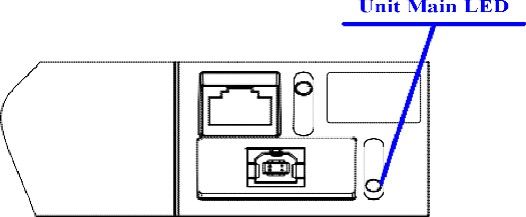
PD-96XXG
                                                                                  Standards and Safety Guidelines

1.5.2   Warnings
          •   Read installation instructions in 4. PoE Midspan Installation before connecting Midspan to its power source.
          •   Read instructions in 4. PoE Midspan Installation before connecting Midspan-to-Midspan power backup.
          •   Only trained and qualified personnel must be allowed to install, replace, and service this equipment.
          •   Midspan must be connected using a grounded power cord, as defined in 1.5.3 Power Cord.
          •   This ITE device must be connected to PoE (power supply over Ethernet) networks only, without routing to other
              networks.
          •   The power cord must not be attached to the surface of the building or pass-through walls, ceilings, floors, and
              similar openings in the building structure.
          •   Steps must be taken to prevent physical damage to the power cord, including proper routing.
          •   This product relies on building installation for short-circuit (over-current) protection. Use only a fuse or circuit
              breaker not higher than 15 A for 120 VAC (U.S.) or 10 A for 230 VAC (international).
          •   All wiring and connections must conform to NFPA 70 (NEC).
          •   Do not work on the system or connect/disconnect cables during lightning storms.
          •   A voltage mismatch can damage the equipment and can pose a fire hazard. If voltage indicated on the label is
              different from the power outlet voltage, do not connect Midspan to this outlet.
          •   For shelf-mounted equipment, verify that surface is stable and strong enough to support the equipment. Do not
              stack more than four Midspan units.
          •   When disposing this product, follow all local laws and regulations.
          •   Data and Data and Power ports of the Midspan are shielded RJ45 data sockets. They cannot be used as Plain
              Old Telephone Service (POTS) sockets. Only connect RJ45 data connectors to these sockets.
          •   Associated Ethernet wiring must be limited to the inside of the building.

1.5.3   Power Cord
        Replacement of power cord must meet the local requirements.
         • To ensure a reliable connection to an AC mains supply, equipment provides an appliance IEC60320 inlet used
            for connecting a detachable power supply cord.
         • Power socket outlet must be located near Midspan and easily accessible. The only way of removing power from
            unit is by disconnecting the power cord from the outlet.
         • This unit operates under Safety Extra Low Voltage (SELV) conditions, according to IEC/EN60950-1 or ES1
            according to IEC/EN 62368-1.
            Note: Conditions are maintained only if the equipment to which the unit is connected also operates under
            SELV/ES1 conditions.

1.5.4   Country-wise Power Cord Specifications

         U.S.A. and Canada          •      Cord must be UL-approved or CSA certified.
                                    •      Minimum specification for flexible cord is:
                                            – No. 18 AWG
                                            – Type SV or SJ
                                            – Three-conductor power cable
                                    •      Cord set must have a rated current capacity of at least 13A.
                                    •      The attachment plug must be an earth-grounding type with a NEMA 5-15P (15 A, 125
                                           V) or NEMA 6-15P (15 A, 250 V) configuration.

         Denmark                  Supply plug must comply with section 107-2-D1, standard DK2-1a or DK2-5a.
         Switzerland              Supply plug must comply with SEV/ASE 1011.
         France and Peru          IT supplies cannot power this unit. If your supplies are an IT type, unit must be powered
                                  by 230 V (2P+T) through an isolation transformer with a 1:1 ratio, and with secondary
                                  connection point labeled Neutral and connected directly to the ground.
         U. K                     PoE Midspan is covered by General Approval NS/G/12345/J/100003, for indirect
                                  connection to a public telecommunications system.

        © 2021 Microchip Technology Inc.                            User Guide                                 DS00004055A-page 5
        and its subsidiaries
PD-96XXG
Information en Matière de Sécurité
2. Information en Matière de Sécurité
Lire les informations suivantes en matière de sécurité avant d'utiliser d'activer l'alimentation sur votre appareil
Ethernet Midspan.
2.1 Directives Générales
Lire les informations suivantes en matière de sécurité avant d'installer ou enlever quoi que ce soit, ou procéder à
l'entretien de l'alimentation de votre appareil Ethernet Midspan. Les mises en garde contiennent des instructions qui
doivent être suivies pour la sécurité des personnes et du produit. Suivre les instructions soigneusement.
2.2 Mises en Garde
• Lire les instructions d'installation dans la cette 4. PoE Midspan Installation avant de connecter le Midspan à une
source d'alimentation.
• Lire les instructions d'installation dans la cette 4. PoE Midspan Installation avant de connecter le Midspan à une
source de sauvegarde Midspan.
• Seul du personnel formé et qualifié doit être autorisé à installer, remplacer et entretenir cet équipement.
• Le Midspan doit être connecté au moyen d'une corde d'alimentation avec prise de terre, comme précisé à la
1.5.3 Power Cord.
• Cet ITE appareil doit être branché à des réseaux PoE (alimentation électrique par Ethernet) seulement, et ce,
sans routage vers d'autres réseaux.
• Le cordon d'alimentation ne doit pas être fixé à la surface du bâtiment ni traverser les murs, les plafonds, les
planchers et les ouvertures similaires de la structure du bâtiment.
• Des mesures doivent être prises pour éviter tout dommage physique au cordon d'alimentation, y compris un
acheminement approprié.
• Ce produit dépend de l'installation électrique de l'immeuble pour une protection contre les courts-circuits
(surcharges de courant). Utiliser seulement un fusible ou un disjoncteur dont la puissance ne dépasse pas
15 A pour 120VAC (É.-U.), ou 10 A pour 230 VAC (international).
• Tout le câblage et les connexions doivent être conformes à la norme NFPA 70 (NEC).
• Ne pas exécuter de travaux sur le système, connecter ou déconnecter des câbles pendant les orages.
• Une disparité de voltage peut endommager l'équipement et constituer un risque d'incendie. Si le voltage indiqué
sur l'étiquette est différent du voltage de la source d'alimentation, ne pas connecter le Midspan à cette prise.
• Pour un équipement monté sur une tablette, vérifier que la surface est stable et suffisamment solide pour le
supporter. Ne jamais empiler plus de quatre unités Midspan.
• Pour disposer/jeter ce produit, suivre les lois et règlements locaux.
• Les ports Data et Data et Power du PoE Midspan sont des prises de données blindées RJ45. Elles ne peuvent
pas être utilisées comme prises de service téléphonique traditionnel. Connecter seulement des connecteurs de
données RJ45 à ces prises. Le câblage Ethernet connexe doit être limité à l'intérieur de l'immeuble.
• Le câblage Ethernet associé doit être limité à l'intérieur du bâtiment.
© 2021 Microchip Technology Inc. User Guide DS00004055A-page 6
and its subsidiariesPD-96XXG
10/100/1000Base-TX Ports Definition
3. 10/100/1000Base-TX Ports Definition
The following sections detail PD-96xxG ports, and their functions.
3.1 Data Input Ports
Midspan has 6 or 12 10/100/1000Base-T Data In ports which are located on PoE front panel, configured in a
non-crossover manner (straight–wired), as shown in Figure 3-1.
These ports are designed to carry Ethernet data (Tx/Rx) over:
• Standard 4-wire pairs (pins 1/2, 3/6, 4/5, and 7/8) (1000Base-T)
• 2-wire pairs (pins 1/2, and 3/6) (10/100Base-T)
3.2 Data and Power Output Ports
Midspan has 6 or 12 10/100/1000Base-T Data and Power Out ports which are located on the front panel, configured
in a non‑crossover manner (straight–wired) as shown in the following figure.
These ports are designed to carry Ethernet data over:
• Standard 4-wire pairs (pins 1/2, 3/6, 4/5, and 7/8) (1000Base-T)
• 2-wire pairs (pins 1/2, and 3/6) (10/100Base-T)
• PD-96xxG series carry DC power over 4-wire pairs (pins 4/5, 7/8 and pins 1/2, 3/6)
Note: The PoE Midspan is not a repeater. Therefore, the maximum distance from Ethernet switch must not exceed
100 meters (328 ft.). The PoE Midspan is guaranteed to work only within this distance, as specified in IEEE 802.3at
standard.
Figure 3-1. Front–View (PD-9612G) of PoE Midspan
3.3 Indicators
A set of indicators displays the status of the PoE Midspan and its ports. For more information about the status
information during operation, see Table 3-1 and Table 3-2.
3.3.1 Power Indicator LED
Power Indicator LED on the front panel displays power status of the PoE Midspan. When this LED is illuminated in
green, it indicates that the Midspan is receiving AC power. For more information, see Table 3-1.
3.3.2 Port Indications
The following sections detail PD-96xxG port indicators.
© 2021 Microchip Technology Inc. User Guide DS00004055A-page 7
and its subsidiariesPD-96XXG
10/100/1000Base-TX Ports Definition
3.3.2.1 PD-96XXG Midspan Series
The bi-color (green and yellow) indicator on each port displays port status:
• Green indicates terminal unit (PD) has been identified as "Power over Ethernet Enabled". It is active and
receiving power over 4-wire pairs.
• Yellow indicates terminal unit (PD) has been identified as "Power over Ethernet Enabled". It is active and
receiving power over 2-wire pairs.
• Blinking green indicates port does not supply power and is inactive.
Note: The PDs that are not PoE-enabled devices are not powered by Midspan.
Table 3-1. Power Status Indications
Indicator Color Main Power Status Remarks
Power Off Power supply unit is —
Indicator unplugged.
Green Power input is active. Power supply voltage is within limits.
Green light blinks once Midspan power supply failure Unit receives backup power and
every second if power (disconnected or out of continues to function normally.
backup is connected. voltage range). Maintenance measures must be taken
whenever possible.
Table 3-2. Port Status Indications for PD-96xx Series
Port LED Color Port Load Conditions Port Voltage
Off Inactive load or unplugged port. Power to port is disconnected. No DC voltage
is present on port output lines.
Green Active load is plugged in and complies Continuous nominal DC voltage is present
with normal load conditions. according to 4-pairs configuration.
Yellow Active load is plugged in and complies Continuous nominal DC voltage is present on
with normal load conditions. 2-wire pairs.
Green blinks once every Overload or short circuit. Power to port is disconnected.
second No DC voltage is present on the port output
lines.
Green blinks once every Valid load. Power is not connected to port.
0.5 seconds Total aggregated power exceeds No DC voltage is present on the port output
predefined power budget. lines.
© 2021 Microchip Technology Inc. User Guide DS00004055A-page 8
and its subsidiariesPD-96XXG
10/100/1000Base-TX Ports Definition
3.4 Connectors
On the front panel of Midspan, there is a Console port. Using a standard USB cable (USB Type B connector), you
can connect a terminal to this port and load the software.
Note: USB connection requires CP210x Driver.exe installation. To install the USB driver, go to: www.silabs.com/
developers/usb-to-uart-bridge-vcp-drivers.
Console port is set to 38,400-baud for managed units and 19,200-baud for unmanaged units, 8 data bits, no parity,
and 1 stop bit.
Figure 3-2. Connecting to Midspan
Ethernet
Switch RJ-IN RJ-OUT PD
Power Bus
1 Data 1 1 Data+DC(-) 1
2 Data 2 2 Data+DC(-) 2
3 Data 3 3 Data+DC(+) 3
RJ-45 4 Data 4 4 Data+DC(+) 4 RJ-45
5 Data 5 5 Data+DC(+) 5
6 Data 6 6 Data+DC(+) 6
7 Data 7 7 Data+DC(-) 7
8 Data 8 8 Data+DC(-) 8
Midspan Channel
Each data port is configured as data “Pass-Through” ports for all data pins (pins 1, 2, 3, 6, 4, 5, 7, and 8). Use cabling
of Category 5 or higher.
© 2021 Microchip Technology Inc. User Guide DS00004055A-page 9
and its subsidiariesPD-96XXG
PoE Midspan Installation
4. PoE Midspan Installation
The following sections describe how to install a PoE Midspan.
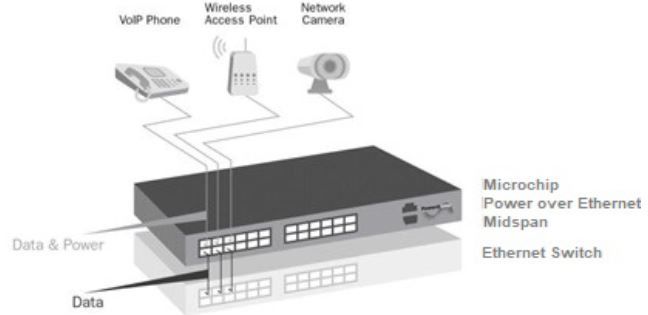
4.1 Background Information
As shown in the following figure, Midspan is connected in series to an Ethernet switch/hub. Switch’s data output
terminals are connected to Midspan. Midspan delivers power over 4-wire twisted pairs (pins 7/8, 4/5 and pins
1/2, 3/6) in PD-96xxG series of Category 5e cabling, without degrading the data quality. Most installations require
Midspan to be rack–mounted.
Figure 4-1. Typical Installation
4.2 Verifying Kit Contents
Unpack the kit and verify that the following items are included:
• PoE Midspan
• Mounting brackets (for 19-inch racks) and a plastic cover
• Screws for assembling mounting brackets
• Self-adhesive rubber feet
• User guide (this file)
• Power Cord
Before proceeding, record the serial number of the unit in the following table for future reference. Serial number is
found on the information label at the back of the PoE Midspan.
Serial Number
© 2021 Microchip Technology Inc. User Guide DS00004055A-page 10
and its subsidiariesPD-96XXG
PoE Midspan Installation
4.3 Rack Mounting Brackets
Midspan comes with 19-inch mounting brackets and screws. To install Midspan into a 19-inch rack:
1. Remove self-adhesive rubber feet from the bottom surface.
2. Install brackets using three screws per side.
Note: Rack-mounting screws are not provided.
Figure 4-2. Installing Mounting Brackets
4.4 Installation Factors
Follow the installation factors carefully:
• Elevated Operating Ambient Temperature: If installed in a closed or multi-unit rack assembly, operating
ambient temperature in rack environment may be greater than room ambient temperature. Therefore, install
equipment in an environment compatible with manufacturer's maximum rated ambient temperature (Tmra).
• Reduced Air Flow: Install the equipment in a rack in a manner that does not compromise the amount of airflow
required for safe operation of the equipment.
• Mechanical Loading: While mounting the equipment into a rack, ensure that mechanical loading is even.
• Circuit Overloading: Consider the connection of equipment to supply circuit and the effect overloading of
circuits might have on over-current protection and supply wiring. Appropriate consideration of equipment
nameplate ratings must be given while addressing this concern.
• Reliable Grounding (Earthing): Maintain reliable earthing of the rack mounted equipment. Pay attention to
supply connections, other than direct connections to branch circuit (for example, the use of power strips).
4.5 Connecting Ethernet Cables
The ports on the front panel of Midspan are configured as "Pass-Through" ports for eight (1, 2, 3, 6, 4, 5, 7, and 8)
conductors of RJ45 connectors. Use Category 5 cabling while connecting.
1. Connect cables from Ethernet Switch to Data In ports (lower row on front panel).
2. Connect cables from PoH or IEEE 802.3at ready terminals (PDs) to corresponding Data and Power Out ports
(upper row on front panel).
4.6 Connecting Power Cables
While using an AC source to power Midspan, plug-in the provided power cord to the AC connector.
© 2021 Microchip Technology Inc. User Guide DS00004055A-page 11
and its subsidiariesPD-96XXG
PoE Midspan Installation
4.7 Powering Up the Unit
PoE Midspan has no ON/OFF switch. To apply or remove power from Midspan, insert or remove power cable to
receptacle (AC) on the back panel of the unit.
With power applied:
• Midspan powers up.
• Internal fan operates.
• Device runs its Power-On Self-Test (POST), which takes less than 10 seconds. During POST, all ports are
disabled and indicators illuminate in the following sequence:
– Port indicators and power indicators illuminate in green.
– Power indicator remains lit in green while port indicators are OFF.
Ports are now ready (enabled) for normal operation.
If LEDs are not lit, see 5. Troubleshooting section for instructions.
© 2021 Microchip Technology Inc. User Guide DS00004055A-page 12
and its subsidiariesPD-96XXG
Troubleshooting
5. Troubleshooting
The following sections describe the troubleshooting procedures to address any problems with a unit.
5.1 Preliminary Steps
If you have a problem with the unit, verify:
• The power is applied to Midspan.
• A crossover-type Ethernet cable is not used.
• Ethernet cable from network is connected to Data port.
• Ethernet cable to PD is connected to Data and Power port.
• Cable pairs are attached to their corresponding ports.
5.2 Troubleshooting Steps
The following table provides a problem and resolution sequence to assist in troubleshooting minor operating
problems. If the following steps do not solve your problem, contact the dealer for further assistance.
Table 5-1.
Problem Corrective Steps
Midspan does not power up. 1. Ensure that the power cord is properly connected.
2. Verify voltage at power inlet is between 100VAC and 240VAC.
3. Remove and reapply power to device and check indicators during
power–up sequence.
A port indicator is not lit 1. Verify port is enabled (Midspan did not detect a PD).
and corresponding PD does not 2. Verify PD is designed for PoE operation.
operate. 3. Verify that you are using a standard Category 5/5e/6, straight-wired
cable, with four pairs.
4. If an external power splitter is in use, replace it with a viable splitter.
5. Verify PD is connected to Data and Power Output port.
6. Try to reconnect the same PD to a different port on the same Midspan
or on another one. If it works, there is probably a faulty output port or
RJ45 connection.
7. Verify port shutdown command was not issued through Web
management.
End device operates, but there is 1. Verify port indicator on front panel is continuously lit.
no data link. 2. If an external power splitter is in use, replace it with a viable splitter.
3. Verify that for this link you are using a standard UTP/FTP Category 5
straight (non-crossover) cabling, with all four pairs, and that link is 100
meters long or less.
4. Try to reconnect the same PD to a different port on the same Midspan
or on another one. If it works, there is probably a faulty port or faulty
RJ45 connection.
© 2021 Microchip Technology Inc. User Guide DS00004055A-page 13
and its subsidiariesPD-96XXG
Specifications
6. Specifications
The following sections detail unit specifications.
6.1 Physical Specifications
Table 6-1. Dimensions
Parameter Dimensions
mm inch
Height 44 1.75
Width 438 17.3
Depth 272 10.8
Table 6-2. Weight Specifications
Part Number Weight
PD-9612G/ACDC/M 5.23 Kg (11.53 lb)
PD-9606G/ACDC/M 4.96 Kg (10.93 lb)
6.2 Environmental Specifications
Table 6-3. Environmental Specifications
Parameter Value
Operating Temperature 0°C to 40°C (32°F to 104°F)
Storage Temperature -20°C to 70°C (-4°F to 158°F)
Humidity 90% max (non-condensing)
6.3 Electrical Specifications
Table 6-4. Electrical Specifications
Part Number Parameter Value
PD-9612G/ACDC/M AC Input Voltage 100 VAC to 240 VAC at 50/60 Hz
PD-9606G/ACDC/M
Input Current at 100 VAC 12 A max
Input Current at 240 VAC 6 A max
Nominal Output Voltage 54 VDC to 57 VDC
Total Output Power 950 W max
Maximum Output Power per Port 95 W
DC Input Rated Voltage 53 VDC - 57 VDC
Input DC Maximum Current 20 A
Note: DC input from power backup Midspan only (not from external DC power supply source).
© 2021 Microchip Technology Inc. User Guide DS00004055A-page 14
and its subsidiariesPD-96XXG
Microchip’s PowerView Pro
7. Microchip’s PowerView Pro
Microchip’s PowerView Pro is a secure remote management system offering real time monitoring and control, with
graphical representation, status indicators, and alarms. PowerView Pro manages Midspans through an Internet
browser interface or through a Network Management System (NMS). Some of the most important features is remote
power enable/disable functionality on each Midspan port, supporting “hard resets” of remote terminals such as WLAN
Access Points and VoIP Phones, and enabling to monitor and control at network and Element levels, as shown in the
following figure. For further details, refer to Microchip’s PowerView Pro Web Manager User Guide.
Figure 7-1. Management Deployment
PowerView Pro provides a number of unique features for Midspan management:
• Remote Web Management of PoE for monitoring and configuration.
• Configuration using graphical representations of remote devices.
• Real-time monitoring and configuration with visual status indicators and alarms.
• Multi-manager capabilities.
• Event and performance data recording.
• Runs on a PC platform with Windows GUI.
Note: The PD-96xxG Midspan comes with the PowerView Pro software pre-installed. If the software needs to be
re-installed or updated, the latest version is located at Microchip’s Software Library.
© 2021 Microchip Technology Inc. User Guide DS00004055A-page 15
and its subsidiariesPD-96XXG
Power Backup and Power Redundancy Connection
8. Power Backup and Power Redundancy Connection
The PD-96xxG has two options for ensuring continuous power supply:
1. Power Backup
2. Power Redundancy
8.1 Power Backup
If one of Midspans' power supplies fails, unit maintains full functionality by using an optional backup power supply.
Table 8-1. Power Backup of PDs
Midspan Unit Redundant Power Supply
PD-9612G/ACDC/M PD-9612G/ACDC/M
PD-9606G/ACDC/M PD-9606G/ACDC/M
8.2 Power Redundancy
Microchip's power redundancy mode is available in the PD-96xxG Midspan series. This mode enables internal power
supply backup for two inter-connected Midspans. This mode provides seamless fail-over between two Midspans. If
internal power supplies of one of the two Midspans fails, it is detected automatically and a working power supply
provides power to the Midspan. Both the Midspans are ensured continuous up-time and all the active ports continue
to operate without any effect on the connected PDs.
Power redundancy mode is available in the following midspans:
• PD-9612G/ACDC/M
• PD-9606G/ACDC/M
Note: While using power redundancy option, connect only units that share the same power supply:
• 1Kw power supply units
– PD-9612G/ACDC/M
– PD-9606G/ACDC/M
Warning: While connecting power redundancy connectors, make sure AC power in both Midspans is disconnected
from AC mains.
8.3 Connectors
Power backup and power redundancy connectors are located on the back side of the Midspan.
PD-96xxG power backup and power redundancy have two connectors, as shown in the following figure:
• Power Backup and Power Redundancy Control Signal Connector, COM D-Sub: 15 pins, 3 rows female
connector.
• DC Voltage Terminal Block Connector has two positive (+) terminals and two negative (-) terminals.
© 2021 Microchip Technology Inc. User Guide DS00004055A-page 16
and its subsidiariesPD-96XXG
Power Backup and Power Redundancy Connection
Figure 8-1. PD-96xxG Rear Panel Connectors
8.4 Connecting Backup and Redundancy Connectors
Warning: Before connecting one Midspan to another, disconnect both Midspans from AC main. Implement Power
Backup and Power Redundancy modes by using DC cable and signal COM cable.
To connect the connectors:
1. Verify Midspans are mounted on rack.
2. Verify Midspans are not connected to AC mains.
3. Connect DC cable; two red wires (+), two black wires (-), and one yellow/green wire, as shown in Figure 8-3.
4. Connect COM cable.
5. Connect Midspans to AC outlet.
6. Verify Power Indicator LED is ON (Green LED).
Note: While connecting a midspan to midspan - connect the earth ground cable between both units Earth Ground
connection.
Figure 8-2. Earth Ground Connection of PDs
© 2021 Microchip Technology Inc. User Guide DS00004055A-page 17
and its subsidiariesPD-96XXG
Power Backup and Power Redundancy Connection
Figure 8-3. PD-96xxG Rear Panel Connections
Notes:
1. If Power Indicator LED is not lit, see 5. Troubleshooting section for instructions.
2. Monitor Backup functionality through NMS, as shown in Figure 8-4.
3. Consult Microchip for information on DC and COM cables.
© 2021 Microchip Technology Inc. User Guide DS00004055A-page 18
and its subsidiariesPD-96XXG
Power Backup and Power Redundancy Connection
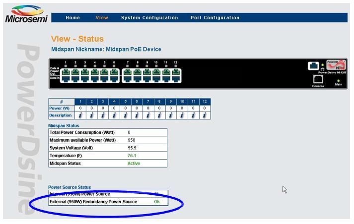
8.5 Power Backup and Power Redundancy Indications
For information on NMS configuration, see PowerView Pro User Guide. During Power Backup and Power
Redundancy, NMS View-Status window displays Power Source Status field. The Power Source Status field shows
both internal and external power supply statuses (green indicates OK and red indicates Fail).
Figure 8-4. PD-9612G View Status in NMS
Note: Midspan provides another power fail indication through Midspan's Power Indicator LED. Whenever unit's
internal power supply fails, Power Indicator LED blinks once every second (Green LED).
Figure 8-5. PD-96xxG Front Panel LED Indication
© 2021 Microchip Technology Inc. User Guide DS00004055A-page 19
and its subsidiariesPD-96XXG
Contacting Technical Support
9. Contacting Technical Support
If you encounter any problems while installing or using this product, consult Microchip technical support team through
the website or contact on the following number:
USA/Canada
Telephone: +1 877 480 2323
Internet: www.microchip.com/support
© 2021 Microchip Technology Inc. User Guide DS00004055A-page 20
and its subsidiariesPD-96XXG
Revision History
10. Revision History
Revision Date Description
A 06/2021 Initial Revision
© 2021 Microchip Technology Inc. User Guide DS00004055A-page 21
and its subsidiariesPD-96XXG
The Microchip Website
Microchip provides online support via our website at www.microchip.com/. This website is used to make files and
information easily available to customers. Some of the content available includes:
• Product Support – Data sheets and errata, application notes and sample programs, design resources, user’s
guides and hardware support documents, latest software releases and archived software
• General Technical Support – Frequently Asked Questions (FAQs), technical support requests, online
discussion groups, Microchip design partner program member listing
• Business of Microchip – Product selector and ordering guides, latest Microchip press releases, listing of
seminars and events, listings of Microchip sales offices, distributors and factory representatives
Product Change Notification Service
Microchip’s product change notification service helps keep customers current on Microchip products. Subscribers will
receive email notification whenever there are changes, updates, revisions or errata related to a specified product
family or development tool of interest.
To register, go to www.microchip.com/pcn and follow the registration instructions.
Customer Support
Users of Microchip products can receive assistance through several channels:
• Distributor or Representative
• Local Sales Office
• Embedded Solutions Engineer (ESE)
• Technical Support
Customers should contact their distributor, representative or ESE for support. Local sales offices are also available to
help customers. A listing of sales offices and locations is included in this document.
Technical support is available through the website at: www.microchip.com/support
Microchip Devices Code Protection Feature
Note the following details of the code protection feature on Microchip devices:
• Microchip products meet the specifications contained in their particular Microchip Data Sheet.
• Microchip believes that its family of products is secure when used in the intended manner and under normal
conditions.
• There are dishonest and possibly illegal methods being used in attempts to breach the code protection features
of the Microchip devices. We believe that these methods require using the Microchip products in a manner
outside the operating specifications contained in Microchip’s Data Sheets. Attempts to breach these code
protection features, most likely, cannot be accomplished without violating Microchip’s intellectual property rights.
• Microchip is willing to work with any customer who is concerned about the integrity of its code.
• Neither Microchip nor any other semiconductor manufacturer can guarantee the security of its code. Code
protection does not mean that we are guaranteeing the product is “unbreakable.” Code protection is constantly
evolving. We at Microchip are committed to continuously improving the code protection features of our products.
Attempts to break Microchip’s code protection feature may be a violation of the Digital Millennium Copyright Act.
If such acts allow unauthorized access to your software or other copyrighted work, you may have a right to sue
for relief under that Act.
© 2021 Microchip Technology Inc. User Guide DS00004055A-page 22
and its subsidiariesPD-96XXG Legal Notice Information contained in this publication is provided for the sole purpose of designing with and using Microchip products. Information regarding device applications and the like is provided only for your convenience and may be superseded by updates. It is your responsibility to ensure that your application meets with your specifications. THIS INFORMATION IS PROVIDED BY MICROCHIP “AS IS”. MICROCHIP MAKES NO REPRESENTATIONS OR WARRANTIES OF ANY KIND WHETHER EXPRESS OR IMPLIED, WRITTEN OR ORAL, STATUTORY OR OTHERWISE, RELATED TO THE INFORMATION INCLUDING BUT NOT LIMITED TO ANY IMPLIED WARRANTIES OF NON-INFRINGEMENT, MERCHANTABILITY, AND FITNESS FOR A PARTICULAR PURPOSE OR WARRANTIES RELATED TO ITS CONDITION, QUALITY, OR PERFORMANCE. IN NO EVENT WILL MICROCHIP BE LIABLE FOR ANY INDIRECT, SPECIAL, PUNITIVE, INCIDENTAL OR CONSEQUENTIAL LOSS, DAMAGE, COST OR EXPENSE OF ANY KIND WHATSOEVER RELATED TO THE INFORMATION OR ITS USE, HOWEVER CAUSED, EVEN IF MICROCHIP HAS BEEN ADVISED OF THE POSSIBILITY OR THE DAMAGES ARE FORESEEABLE. TO THE FULLEST EXTENT ALLOWED BY LAW, MICROCHIP'S TOTAL LIABILITY ON ALL CLAIMS IN ANY WAY RELATED TO THE INFORMATION OR ITS USE WILL NOT EXCEED THE AMOUNT OF FEES, IF ANY, THAT YOU HAVE PAID DIRECTLY TO MICROCHIP FOR THE INFORMATION. Use of Microchip devices in life support and/or safety applications is entirely at the buyer’s risk, and the buyer agrees to defend, indemnify and hold harmless Microchip from any and all damages, claims, suits, or expenses resulting from such use. No licenses are conveyed, implicitly or otherwise, under any Microchip intellectual property rights unless otherwise stated. Trademarks The Microchip name and logo, the Microchip logo, Adaptec, AnyRate, AVR, AVR logo, AVR Freaks, BesTime, BitCloud, chipKIT, chipKIT logo, CryptoMemory, CryptoRF, dsPIC, FlashFlex, flexPWR, HELDO, IGLOO, JukeBlox, KeeLoq, Kleer, LANCheck, LinkMD, maXStylus, maXTouch, MediaLB, megaAVR, Microsemi, Microsemi logo, MOST, MOST logo, MPLAB, OptoLyzer, PackeTime, PIC, picoPower, PICSTART, PIC32 logo, PolarFire, Prochip Designer, QTouch, SAM-BA, SenGenuity, SpyNIC, SST, SST Logo, SuperFlash, Symmetricom, SyncServer, Tachyon, TimeSource, tinyAVR, UNI/O, Vectron, and XMEGA are registered trademarks of Microchip Technology Incorporated in the U.S.A. and other countries. AgileSwitch, APT, ClockWorks, The Embedded Control Solutions Company, EtherSynch, FlashTec, Hyper Speed Control, HyperLight Load, IntelliMOS, Libero, motorBench, mTouch, Powermite 3, Precision Edge, ProASIC, ProASIC Plus, ProASIC Plus logo, Quiet-Wire, SmartFusion, SyncWorld, Temux, TimeCesium, TimeHub, TimePictra, TimeProvider, WinPath, and ZL are registered trademarks of Microchip Technology Incorporated in the U.S.A. Adjacent Key Suppression, AKS, Analog-for-the-Digital Age, Any Capacitor, AnyIn, AnyOut, Augmented Switching, BlueSky, BodyCom, CodeGuard, CryptoAuthentication, CryptoAutomotive, CryptoCompanion, CryptoController, dsPICDEM, dsPICDEM.net, Dynamic Average Matching, DAM, ECAN, Espresso T1S, EtherGREEN, IdealBridge, In-Circuit Serial Programming, ICSP, INICnet, Intelligent Paralleling, Inter-Chip Connectivity, JitterBlocker, maxCrypto, maxView, memBrain, Mindi, MiWi, MPASM, MPF, MPLAB Certified logo, MPLIB, MPLINK, MultiTRAK, NetDetach, Omniscient Code Generation, PICDEM, PICDEM.net, PICkit, PICtail, PowerSmart, PureSilicon, QMatrix, REAL ICE, Ripple Blocker, RTAX, RTG4, SAM-ICE, Serial Quad I/O, simpleMAP, SimpliPHY, SmartBuffer, SMART-I.S., storClad, SQI, SuperSwitcher, SuperSwitcher II, Switchtec, SynchroPHY, Total Endurance, TSHARC, USBCheck, VariSense, VectorBlox, VeriPHY, ViewSpan, WiperLock, XpressConnect, and ZENA are trademarks of Microchip Technology Incorporated in the U.S.A. and other countries. SQTP is a service mark of Microchip Technology Incorporated in the U.S.A. The Adaptec logo, Frequency on Demand, Silicon Storage Technology, and Symmcom are registered trademarks of Microchip Technology Inc. in other countries. GestIC is a registered trademark of Microchip Technology Germany II GmbH & Co. KG, a subsidiary of Microchip Technology Inc., in other countries. All other trademarks mentioned herein are property of their respective companies. © 2021, Microchip Technology Incorporated, Printed in the U.S.A., All Rights Reserved. ISBN: 978-1-5224-8358-8 © 2021 Microchip Technology Inc. User Guide DS00004055A-page 23 and its subsidiaries
PD-96XXG

Quality Management System
For information regarding Microchip’s Quality Management Systems, please visit www.microchip.com/quality.

© 2021 Microchip Technology Inc.                      User Guide                             DS00004055A-page 24
and its subsidiaries
Worldwide Sales and Service
 AMERICAS                          ASIA/PACIFIC             ASIA/PACIFIC              EUROPE
 Corporate Office                  Australia - Sydney       India - Bangalore         Austria - Wels
 2355 West Chandler Blvd.          Tel: 61-2-9868-6733      Tel: 91-80-3090-4444      Tel: 43-7242-2244-39
 Chandler, AZ 85224-6199           China - Beijing          India - New Delhi         Fax: 43-7242-2244-393
 Tel: 480-792-7200                 Tel: 86-10-8569-7000     Tel: 91-11-4160-8631      Denmark - Copenhagen
 Fax: 480-792-7277                 China - Chengdu          India - Pune              Tel: 45-4485-5910
 Technical Support:                Tel: 86-28-8665-5511     Tel: 91-20-4121-0141      Fax: 45-4485-2829
 www.microchip.com/support         China - Chongqing        Japan - Osaka             Finland - Espoo
 Web Address:                      Tel: 86-23-8980-9588     Tel: 81-6-6152-7160       Tel: 358-9-4520-820
 www.microchip.com                 China - Dongguan         Japan - Tokyo             France - Paris
 Atlanta                           Tel: 86-769-8702-9880    Tel: 81-3-6880- 3770      Tel: 33-1-69-53-63-20
 Duluth, GA                        China - Guangzhou        Korea - Daegu             Fax: 33-1-69-30-90-79
 Tel: 678-957-9614                 Tel: 86-20-8755-8029     Tel: 82-53-744-4301       Germany - Garching
 Fax: 678-957-1455                 China - Hangzhou         Korea - Seoul             Tel: 49-8931-9700
 Austin, TX                        Tel: 86-571-8792-8115    Tel: 82-2-554-7200        Germany - Haan
 Tel: 512-257-3370                 China - Hong Kong SAR    Malaysia - Kuala Lumpur   Tel: 49-2129-3766400
 Boston                            Tel: 852-2943-5100       Tel: 60-3-7651-7906       Germany - Heilbronn
 Westborough, MA                   China - Nanjing          Malaysia - Penang         Tel: 49-7131-72400
 Tel: 774-760-0087                 Tel: 86-25-8473-2460     Tel: 60-4-227-8870        Germany - Karlsruhe
 Fax: 774-760-0088                 China - Qingdao          Philippines - Manila      Tel: 49-721-625370
 Chicago                           Tel: 86-532-8502-7355    Tel: 63-2-634-9065        Germany - Munich
 Itasca, IL                        China - Shanghai         Singapore                 Tel: 49-89-627-144-0
 Tel: 630-285-0071                 Tel: 86-21-3326-8000     Tel: 65-6334-8870         Fax: 49-89-627-144-44
 Fax: 630-285-0075                 China - Shenyang         Taiwan - Hsin Chu         Germany - Rosenheim
 Dallas                            Tel: 86-24-2334-2829     Tel: 886-3-577-8366       Tel: 49-8031-354-560
 Addison, TX                       China - Shenzhen         Taiwan - Kaohsiung        Israel - Ra’anana
 Tel: 972-818-7423                 Tel: 86-755-8864-2200    Tel: 886-7-213-7830       Tel: 972-9-744-7705
 Fax: 972-818-2924                 China - Suzhou           Taiwan - Taipei           Italy - Milan
 Detroit                           Tel: 86-186-6233-1526    Tel: 886-2-2508-8600      Tel: 39-0331-742611
 Novi, MI                          China - Wuhan            Thailand - Bangkok        Fax: 39-0331-466781
 Tel: 248-848-4000                 Tel: 86-27-5980-5300     Tel: 66-2-694-1351        Italy - Padova
 Houston, TX                       China - Xian             Vietnam - Ho Chi Minh     Tel: 39-049-7625286
 Tel: 281-894-5983                 Tel: 86-29-8833-7252     Tel: 84-28-5448-2100      Netherlands - Drunen
 Indianapolis                      China - Xiamen                                     Tel: 31-416-690399
 Noblesville, IN                   Tel: 86-592-2388138                                Fax: 31-416-690340
 Tel: 317-773-8323                 China - Zhuhai                                     Norway - Trondheim
 Fax: 317-773-5453                 Tel: 86-756-3210040                                Tel: 47-72884388
 Tel: 317-536-2380                                                                    Poland - Warsaw
 Los Angeles                                                                          Tel: 48-22-3325737
 Mission Viejo, CA                                                                    Romania - Bucharest
 Tel: 949-462-9523                                                                    Tel: 40-21-407-87-50
 Fax: 949-462-9608                                                                    Spain - Madrid
 Tel: 951-273-7800                                                                    Tel: 34-91-708-08-90
 Raleigh, NC                                                                          Fax: 34-91-708-08-91
 Tel: 919-844-7510                                                                    Sweden - Gothenberg
 New York, NY                                                                         Tel: 46-31-704-60-40
 Tel: 631-435-6000                                                                    Sweden - Stockholm
 San Jose, CA                                                                         Tel: 46-8-5090-4654
 Tel: 408-735-9110                                                                    UK - Wokingham
 Tel: 408-436-4270                                                                    Tel: 44-118-921-5800
 Canada - Toronto                                                                     Fax: 44-118-921-5820
 Tel: 905-695-1980
 Fax: 905-695-2078

© 2021 Microchip Technology Inc.                           User Guide                          DS00004055A-page 25
and its subsidiaries
You can also read