Instruction Manual For Model TC-36-25 RS485 Thermoelectric Cooler Temperature Controller
←
→
Page content transcription
If your browser does not render page correctly, please read the page content below
Instruction Manual
                 For
        Model TC-36-25 RS485
        Thermoelectric Cooler
       Temperature Controller

                     February 12, 2019
                    Drawing #5106 Rev. C

               TE
1590 Keane Drive
                          TECHNOLOGY, INC.
                                                  ®
                                             Phone: (231) 929-3966
Traverse City, MI 49696-8257                 Fax: (231) 929-4163
http://www.tetech.com                        e-mail: cool@tetech.com

          All Materials Copyright © 2012, TE Technology, Inc.
General Safety Warnings

This manual is available in English only. It must be read and followed carefully before installation and operation.

         THE LATEST REVISION OF THIS MANUAL IS AVAILABLE AT www.tetech.com. Verify that you are using the
         latest revision available.

         The TC-36-25 RS485 should not be used as a toy, or serious injury could result. The TC-36-25 RS485 should
         only be used for its intended purpose of providing temperature control of TE Technology’s thermoelectric
         devices only. The controller is intended for light industrial, laboratory, or similar use. It is not intended for
         household use or medical use.

         Do not use in an explosive or potentially explosive environment.

         Do not use the TC-36-25 RS485 to control capacitive or inductive loads or the controller could be
         damaged and/or overheat. Examples of capacitive or inductive loads include but are not limited to
         motors, fans, filters, and solenoids.

         Do not allow the electrical connections on the printed circuit board to touch any electrically conductive
         surfaces.

         Do not operate in an environment where the controller could come in contact with condensation, water,
         metal shavings, dirt or other contaminants, or electrically conductive materials.

         Use ESD (Electro Static Discharge) protection when installing the controller or coming in contact with
         electrical connections or components on the controller.

         Do not touch any of the electrical connections or components of the TC-36-25 RS485 while the controller
         is energized. Doing so can disrupt the function of the controller.

         Do not use if the controller has been damaged in any way.

         Only qualified technicians should install and operate this controller with the appropriate personal
         protective equipment.

         Improper tuning of this temperature controller can lead to excessive thermal cycling and/or overheating
         of the thermoelectric device, either of which are known to reduce the lifetime of any thermoelectric
         device. Care should be taken to prevent the temperature of the thermoelectric device from going beyond
         the range specified by the device manufacturer. Care should also be taken so that any thermal cycling of
         the thermoelectric device is a result of changes in the controller’s set-point temperature and not
         instability at a given set point due to improper selection of the tuning variables.

         The temperature controller base underneath the transistor-mounting area could exceed 60 °C under
         normal operation. Use caution! Protect against accidental contact with hot surfaces.

         Use protection devices to prevent hazardous conditions and/or damage to equipment.

         Each power input that is used with the controller must be fused separately. Alternatively, a power supply
         with integral over-current protection may be used if it is appropriately sized for protecting the
         controller/TE device.

         The temperature controller is intended to be used with, or incorporated into, other machinery made by
         TE Technology, Inc. and must not be put into service until the relevant machinery into which it is to be
         incorporated into has been declared in conformity with the essential requirements of the Machinery
         Directive 2006/42/EC.

                                                        2
For more information regarding protection devices read, TE Technology’s Thermoelectric Cooling Assembly (TCA)
Instruction manual which is available for download from TE Technology's website at www.tetech.com. The terms and
provisions relating to protection devices as provided in the TCA Instruction manual are herby incorporated by reference.
A copy of the TCA Instruction manual can also be sent via regular mail upon request.

TE Technology, Inc. does not make any warranty, expressed or implied, that the use or operation of the equipment will be
functional or effective if the equipment is not installed and used in accordance with this manual.

TE Technology, Inc. shall not be liable, and Purchaser shall defend, hold harmless, and indemnify TE Technology, Inc. from
and against, any losses, costs, expenses (including reasonable attorneys’ fees), injuries, liabilities or damages of any kind
or nature whatsoever, arising out of the use or inability to use this TE Technology, Inc. product, from the omission or
failure to use protection devices, or from failure to comply with this manual. This provision is in addition to any other
indemnification provisions which are a part of the Purchase Order or contract with Purchaser.

                                                              3
Table of Contents

License Agreement ................................................................................................................................................................... 5

Features .................................................................................................................................................................................... 8

Setup Instructions................................................................................................................................................................... 14

    1.0         Initial Setup ........................................................................................................................................................... 14

    2.0         Controller Setup .................................................................................................................................................... 20

    3.0         FINAL SETUP—CONTROLLER TUNING ................................................................................................................... 31

Controller Wiring Diagram: TC-36-25 RS485 with One Power Supply Setup ......................................................................... 34

Controller Wiring Diagram: TC-36-25 RS485 with Two Power Supplies Setup ...................................................................... 35

Expansion Connector Wiring Diagram .................................................................................................................................... 36

Mechanical Package Drawing ................................................................................................................................................. 37

Block Diagram ......................................................................................................................................................................... 37

RS485 Communications Connections ..................................................................................................................................... 39

Appendix A Troubleshooting Controller ................................................................................................................................. 40

APPENDIX B: Troubleshooting Communications ................................................................................................................... 42

APPENDIX C: Serial Communications..................................................................................................................................... 43

APPENDIX D: Thermistors for TC-36-25 RS485 ....................................................................................................................... 56

APPENDIX E: Multiple Controller (RS-485) Wiring Diagram .................................................................................................. 61

                                                                                              4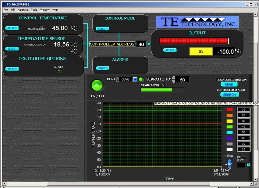
TE TECHNOLOGY, INC. (TE TECH)
                                                          License Agreement
CAREFULLY READ THE FOLLOWING TERMS AND CONDITIONS BEFORE OPENING THIS PACKAGE OR SIGNIFYING YOUR ACCEPTANCE BY CLICKING THE APPROPRIATE DIALOG
BOX. OPENING THIS PACKAGE, CLICKING THE APPROPRIATE DIALOG BOX OR USING ANY PART OF THE SOFTWARE SIGNIFIES YOUR ACCEPTANCE OF (1) THESE TERMS AND
CONDITIONS FOR THE LICENSED SOFTWARE, AND (2) THE TERMS OF ACCEPTANCE OF TE TECH FOR ANY PRODUCTS PURCHASED FROM TE TECH. IF YOU DO NOT AGREE WITH
THEM, PROMPTLY RETURN THE PACKAGE UNOPENED AND UNUSED ALONG WITH ANY OTHER ITEM THAT WAS INCLUDED IN THE SAME PRODUCT NUMBER FOR FULL CREDIT.

You, as the Customer, agree as follows:

1.           DEFINITIONS

“Application Software” shall mean those portions of the Licensed Software created by TE TECH.

“Designated Hardware” shall mean the one (1) hardware device, purchased from TE TECH, upon which Customer shall run the Licensed Software.

“Licensed Software” shall mean the Application Software plus any other software supplied by TE TECH pursuant to this Agreement.

“Third Party Software” shall mean software owned or licensed by a third party, including but not limited to operating systems, that is embedded within the Licensed Software
or otherwise included with any product provided to Customer from TE TECH.

2.           LICENSE

2.1           Except as provided in section 2.2 below, you are granted only a personal, non-transferable, nonexclusive license to use the Licensed Software only on the
Designated Hardware. You may copy the Licensed Software into machine readable form for backup purposes or to support your use of the Licensed Software on the
Designated Hardware. No other copies shall be made unless authorized in writing by TE TECH. You may not (i) reverse engineer, decompile, or disassemble the Licensed
Software (except to the extent such foregoing restriction is expressly prohibited by applicable law); (ii) sub-license, lease, or rent the Licensed Software; (iii) distribute in part,
modify, or create derivatives of the Licensed Software; (iv) amend, modify, or supplement Licensed Software with any additional code except for the purpose of further
configuring the Licensed Software for use with Designated Hardware; or (v) directly or indirectly, export, re-export, download, or ship the Licensed Software in violation of the
laws and regulations of the U.S. The Licensed Software, comprising proprietary trade secret information of TE TECH and/or its Licensor’s, shall be held in confidence by
Customer and protected from disclosure to third parties. No title to the intellectual property is transferred, You must reproduce and include all applicable copyright notices on
any copy. Licensed Software shall not be copied, reproduced, or used for any other purpose outside of operation of the TE TECH hardware, and shall not be used on any other
piece of hardware other than the TE TECH hardware with, or for, which it was provided. Notwithstanding the foregoing, in the event that you download the Licensed Software
from the internet without purchasing Designated Hardware, the Licensed Software may only be used for evaluation purposes and must be deleted (including all copies) within
fifteen (15) days of downloading. You may not use the Licensed Software with any other equipment other than the Designated Hardware without prior written approval from
TE TECH. If no operating system software is included in the software provided under this Agreement, you must make provision for any required operating system software
licenses. At its option, TE TECH may, upon request, provide the source code for the Licensed Software. The limited warranty provided in section 3 below shall be null and void
immediately upon TE TECH providing the source code, or any portion thereof, to you.

2.2          If you are an authorized TE TECH distributor or an Original Equipment Manufacturer who incorporates the Licensed Software into your equipment for sale to an
end user, or you use the Licensed Software to create redistributables, you may transfer the Licensed Software to an end user provided that the end user agrees to be bound
by the provisions of this Agreement. You shall use your best efforts to enforce your agreement with customers made in accordance with this Section 2.2 and shall promptly
report any violation or suspected violation to TE TECH. In the event that your customer violates any portion of this agreement, you agree to defend, hold harmless and
indemnify TE TECH from any and all such claims. TE TECH may, at its option, bring suit against your customer to enforce the terms of this agreement, TE TECH’s costs and
expenses incurred as a result of such action (including reasonable attorneys’ fees) shall be your responsibility.

2.3          The Licensed Software may include Third Party Software licensed to TE TECH. Customer hereby acknowledges and agrees that any Third Party Software provided
by TE TECH to Customer hereunder (a) shall not be modified and shall be used and/or used and redistributed or resold (to the extent permitted under Section 2.2) only
embedded within the TE TECH hardware product as provided by TE TECH, (b) shall always contain and only be redistributed (to the extent permitted under Section 2.2) with
all proprietary markings present as provided to Customer hereunder and under the same terms and conditions as set forth in this Agreement. All rights and benefits afforded
to TE TECH under this Agreement shall apply equally to the owner of the Third Party Software (the “Third Party”) and its licensors with respect to the Third Party Software. The
Third Party and its licensors are intended third party beneficiaries of this Agreement, and the provisions of this Agreement relating to the Licensed Software, as the same
incorporate the Third Party Software, are made expressly for the benefit of, and are enforceable by, the Third Party and its licensors. The Third Party and its licensors retain
ownership of all copies of the Third Party Software. Unless a pass-through warranty covering the Third Party Software is extended directly to you by the Third Party, all
Third Party Software is provided “AS IS” without warranty of any kind, and each Third Party and its licensors disclaim all warranties, either express or implied, including
but not limited to the implied warranties of merchantability, title, non-infringement or fitness for a particular purpose with regard to the Third Party Software. The Third
Party shall not have any liability for special, indirect, punitive, incidental or consequential damages.

2.4         EXCEPT AS PROVIDED IN SECTION 2.2 ABOVE, IF YOU TRANSFER POSSESSION OF ANY COPY OF THE LICENSED SOFTWARE TO ANOTHER PARTY WITHOUT WRITTEN
CONSENT OF TE TECH, YOUR LICENSE IS AUTOMATICALLY TERMINATED. Any attempt otherwise to sublicense, assign or transfer any of the right, duties or obligations
hereunder is void.

2.5          If the Licensed Software or associated documentation is provided to any U.S. Government entity, unit, or agency, the restrictions set forth at section 52.227-19(c)
(“Commercial computer software - restricted rights”) of the Federal Acquisition Regulations (FARs) shall apply. If the Licensed Software or associated documentation is
provided to the U.S. Government, Department of Defense (DOD), or any entity, unit, or agency thereof, the restrictions set forth at section 252.227-7015 (“Technical Data -
Commercial Items”) of the DOD FAR Supplement (DFARS) shall also apply.

2.6         For rights granted in this Agreement, Customer shall pay to TE TECH the then-current product price (license fee) for each copy of the Licensed Software provided
by TE TECH to Customer.

2.7         Customer shall pay all import duties and registration fees and all sales, use and excise taxes (and any other assessments in the nature of taxes however
designated) on the Licensed Software or its license to use the Licensed Software, or resulting from this Agreement, exclusive of taxes based on TE TECH’s net income.

2.8          Customer acknowledges that the Licensed Software, including, without limitation, TE TECH logos, trademarks and all information contained therein, is proprietary
to TE TECH, is valuable, gives a competitive advantage to TE TECH, and could not, without significant expense and difficulty, be obtained or duplicated by others who have not
been able to acquire the same through means expressly authorized in this agreement. You agree that, unless you first obtain the prior written consent of TE TECH ,or unless

                                                                                          5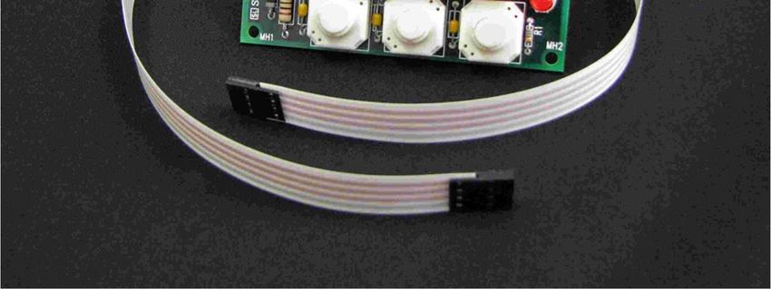
required by law, you shall not communicate or disclose, directly or indirectly, to any person or firm, or use at any time, any of the TE TECH’s proprietary information, except as
provided in this Agreement. The provisions of the section, among certain others, shall survive the termination of this Agreement for whatever reason. The Licensed Software
shall be and remain the exclusive property of TE TECH.

3.           WARRANTY

3.1          Only if Customer has purchased Designated Hardware (the purchase price of which automatically includes the license fee), TE TECH warrants that the Application
Software will be in substantial conformance with the specifications in the manual pertaining thereto as of the date of shipment by TE TECH. If, within ninety (90) days of date
of shipment, it is shown that the Application Software does not meet this warranty, TE TECH will, at its option, either correct the defect or error in the Application Software,
free of charge, or make available to Customer satisfactory substitute software, or, as a last resort, return to Customer all payments made as license fees and terminate the
license with respect to the Application Software affected. TE TECH does not warrant that operation of the Application Software will be uninterrupted or error free or that it
will meet Customer’s needs. All other portions of the Licensed Software are provided “as is” without warranty of any kind.

3.2           TE TECH warrants that the media on which the Application Software is delivered will be free from defects in material or workmanship under normal use and
service for a period of ninety (90) days from the date of delivery. If any defects are discovered in the media is discovered and reported by Customer within ninety (90) days
after delivery TE TECH shall, at no cost to Customer, upon return of same to TE TECH, replace the media and deliver (electronically) to Customer a new and complete copy of
the Licensed Software.

3.3          Any modification to the Licensed Software by the Customer without the express written consent of TE TECH shall void the warranty.

3.4        THE FOREGOING WARRANTIES ARE EXCLUSIVE AND ARE IN LIEU OF ALL OTHER WARRANTIES WITH RESPECT TO THE LICENSED SOFTWARE WHETHER WRITTEN,
ORAL, IMPLIED OR STATUTORY. NO IMPLIED OR STATUTORY WARRANTY OF MERCHANTABILITY OR FITNESS FOR A PARTICULAR PURPOSE SHALL APPLY. NO WARRANTY
ARISING FROM COURSE OF PERFORMANCE, COURSE OF DEALING, OR USAGE OF TRADE SHALL APPLY. NOTWITHSTANDING ANYTHING TO THE CONTRARY HEREIN, UNLESS
CUSTOMER HAS PAID TE TECH A SEPARATE LICENSE FEE THEREFOR, TE TECH MAKES NO WARRANTIES AS TO THE LICENSED SOFTWARE, WHICH IS PROVIDED “AS IS”
WITHOUT WARRANTY OF ANY KIND, WHETHER EXPRESS OR IMPLIED.

4.           LIMITATION OF LIABILITY

4.1         IN NO EVENT, WHETHER AS A RESULT OF BREACH OF CONTRACT, BREACH OF WARRANTY, TORT (INCLUDING NEGLIGENCE) OR OTHERWISE, SHALL TE TECH OR
ITS SUPPLIERS BE LIABLE FOR ANY SPECIAL, CONSEQUENTIAL, INCIDENTAL OR PENAL DAMAGES INCLUDING, BUT NOT LIMITED TO, LOSS OF PROFIT OR REVENUES, LOSS OF
USE OF THE LICENSED SOFTWARE OR ANY PART THEREOF, OR ANY ASSOCIATED EQUIPMENT, DAMAGE TO ASSOCIATED EQUIPMENT, COST OF CAPITAL, COST OF SUBSTITUTE
PRODUCTS, FACILITIES, SERVICES OR REPLACEMENT POWER, DOWN TIME COSTS, OR CLAIMS OF CUSTOMER’S CUSTOMERS AND TRANSFEREES FOR SUCH DAMAGES EVEN IF
TE TECH HAS BEEN ADVISED OF THE POSSIBILITY OF SUCH DAMAGES.

4.2        EXCEPT AS PROVIDED IN SECTION 5, INDEMNITY, IN NO EVENT, WHETHER AS A RESULT OF BREACH OF CONTRACT OR WARRANTY, TORT (INCLUDING
NEGLIGENCE) OR OTHERWISE, SHALL TE TECH’S LIABILITY TO CUSTOMER FOR ANY LOSS OR DAMAGE ARISING OUT OF, OR RESULTING FROM THIS AGREEMENT, OR FROM ITS
PERFORMANCE OR BREACH, OR FROM THE LICENSED SOFTWARE OR ANY PART THEREOF, OR FROM ANY SERVICE FURNISHED HEREUNDER, EXCEED THE QUOTED CHARGES
FOR THE LICENSED SOFTWARE. ANY SUCH LIABILITY SHALL TERMINATE UPON THE TERMINATION OF THE WARRANTY PERIOD AS SET FORTH IN SECTION 3.

4.3         If TE TECH furnishes Customer with advice or other assistance which concerns Licensed Software or any portion thereof supplied hereunder or any system or
equipment on which any such software may be installed and which is not required pursuant to this Agreement the furnishing of such advice or assistance will not subject TE
TECH to any liability, whether in contract, warranty, tort (including negligence) or otherwise.

4.4          The products (hardware and software) to be licensed or sold hereunder are not intended for use in any application specifically prohibited in writing by TE TECH,
including, without limitation, in any nuclear, chemical or weapons production facility or activity, or other activity where failure of the products could lead directly to death,
personal injury or severe physical or environmental damage. If so used, TE TECH disclaims all liability for any damages arising as a result of the hazardous nature of the
business in question, including but not limited to nuclear, chemical or environmental damage, injury or contamination, and Customer shall indemnify, hold harmless and
defend TE TECH, its officers, directors, employees and agents against all such liability, whether based on contract, warranty, tort (including negligence), or any other legal
theory, regardless of whether TE TECH had knowledge of the possibility of such damages.

5.           INDEMNITY

5.1           Should the Application Software be held by a court to constitute patent or copyright infringement and its use is enjoined, TE TECH shall, at its expense and option,
either procure for Customer the right to continued use, or replace same with a non-infringing product or part, or modify the Application Software so that it becomes non-
infringing, or remove the software and refund the license charge pertaining thereto (less reasonable depredation for any period of use) and any transportation costs
separately paid by Customer. The foregoing states the entire liability of TE TECH for patent and copyright infringement by the Licensed Software or any part thereof.

5.2          The indemnity under the preceding paragraph shall not apply to any use of Application Software in conjunction with any other product in a combination not
furnished by TE TECH as a part of this transaction. As to any such use in such combination, or any improper or unauthorized use, installation, or operation of the Application
Software, TE TECH assumes no liability whatsoever for patent and copyright infringement and Customer will hold TE TECH harmless against any infringement claims arising
there from (including, but not limited to, reasonable attorney’s fees).

6.           TERM AND TERMINATION

6.1          You may terminate the license granted hereunder at any time by destroying the Licensed Software together with all copies thereof and notifying TE TECH in
writing that all use of the Licensed Software has ceased and that same has been destroyed.

6.2         TE TECH, upon thirty (30) days’ notice, may terminate this Agreement or any license hereunder if Customer fails to perform any obligation or undertaking to be
performed by it under this Agreement or if Customer attempts to assign this Agreement without the prior written consent of TE TECH. Within twenty (20) days after any such
termination of this Agreement, Customer shall certify in writing to TE TECH that all use of the Licensed Software has ceased, and that same has been returned or destroyed, in
accordance with TE TECH’s instructions.

6.3           Sections 4, 6 and 7 of this Agreement shall survive any expiration or termination and remain in effect. Termination of this Agreement or any license hereunder
shall not relieve Customer of its obligation to pay any and all outstanding charges hereunder nor entitle Customer to any refund of such charges previously paid.

                                                                                        6
7.          IMPORT/EXPORT

7.1         If you intend to import or export (or re-export), directly or indirectly, whether electronically or otherwise, the software products or technical data relating thereto
supplied hereunder or any portion thereof, it is your responsibility to assure compliance with U.S. and other applicable governmental import and/or export control laws and, if
appropriate, to secure any required licenses or approvals in your own name. You are also responsible for the accuracy and completeness of any information or certification
you provide for purposes of import or export control compliance.

8.          GENERAL

8.1          This Agreement shall be governed by the laws of the State of Michigan, without regard to its conflict of law provisions. You agree that any civil action or claims
which relate to this Agreement or the Licensed Software must be brought and maintained in a court of competent jurisdiction located in Grand Traverse County, Michigan, or,
alternatively, the U.S. District court for the Western District of Michigan. You hereby waive venue in any other forum. The provisions of the United Nations Convention on the
International Sale of Goods shall not apply to this Agreement

8.2         Should you have any questions concerning this Agreement, contact TE TECH by writing to: TE TECHNOLOGY, INC., 1590 KEANE DRIVE, TRAVERSE CITY, MI 49686.

8.3       YOU ACKNOWLEDGE THAT YOU HAVE READ THIS AGREEMENT, UNDERSTAND IT AND AGREE TO BE BOUND BY ITS TERMS AND CONDITIONS. YOU FURTHER
AGREE THAT IT IS THE COMPLETE AND EXCLUSIVE STATEMENT OF THE AGREEMENT BETWEEN US AND SUPERSEDES ANY PROPOSAL OR PRIOR AGREEMENT, ORAL OR
WRITTEN, AND ANY OTHER COMMUNICATIONS BETWEEN US RELATING TO THE SUBJECT MATTER OF THIS AGREEMENT. FURTHER, NO CHANGE OR AMENDMENT TO THIS
AGREEMENT SHALL BE EFFECTIVE UNLESS AGREED TO BY WRITTEN INSTRUMENT SIGNED BY A DULY AUTHORIZED REPRESENTATIVE OF TE TECH.

                                                                                        7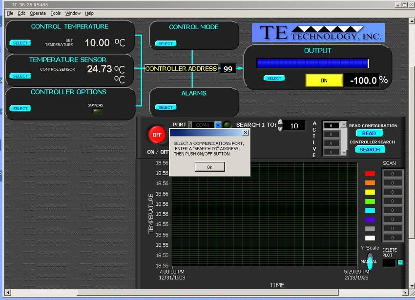
Features

TC-36-25 RS485, Thermistor, I/O Cable, and Software

The TC-36-25 RS485 provides bi-directional (heating and cooling) temperature control for thermoelectric devices.
Resistive heaters can also be controlled. An H-bridge configuration is used for the power output stage. The output stage
is made from solid-state N-channel MOSFETs (no relays or mechanical components are used). These transistors are highly
efficient and allow for the bi-directional flow of current through the thermoelectric coolers. Their high efficiency reduces
the waste heat generated by the controller and allows for a compact design.

The TC-36-25 RS485 controller is programmable via a RS-485 port or RS-485 port adapter. The TC-36-25 RS485 can be
networked with up to 254 controllers on one RS485 communications port. Field selectable parameters or data acquisition
in a half duplex mode can be performed. The supplied software is compatible with Windows 10/8/7. The software
provides a graphical user interface for setting control parameters and receiving feedback from the temperature sensor(s).
However, the command set is also provided so that qualified personnel can use the controller as an embedded control, or
they can create a custom program interface. The software can also be used to instruct the TC-36-25 RS485 to save the
desired control parameters to the controller’s non-volatile memory. This allows the controller to be disconnected from
the computer and operated as a stand-alone controller. When operating as a stand-alone controller, the controller can be
set to always control to the stored set point or it can be set up to accept a proportional signal to vary the set point as
required.

Mechanically, the controller’s printed circuit board is mounted to a metal bracket that is suitable for either horizontal or
vertical orientation. The controller can operate in ambient temperatures from 0 °C to 60 °C without generally requiring
additional heat sinking. The controller is intended to be used in locations where the controller can be protected by a
secondary enclosure or other means of protection.

                                                              8
The MP-2986 Display and Keypad, shown below, is an optional accessory that can be purchased separately. It provides a
convenient way of showing and adjusting the temperature set point or showing the actual temperature being sensed
when the TC-36-25 RS485 is operating as a stand-alone controller. See the MP-2986 manual for further information.

                                         MP-2986 External Display and Keypad

                                                           9
Main Features
RoHS compliant
Operates as a stand-alone controller or with a computer monitor
Bi-directional, solid-state H-bridge operation for both heating and cooling
Can be configured to control both high and low voltage thermoelectric (TE) devices:
Single power supply configuration for TE devices with an input voltage range from (12 to 36) VDC
Dual power supply configuration for TE devices with an input voltage range is less than 12 VDC:
o Controller-circuitry input voltage range from (12 to 36) VDC
o TE device (H-Bridge) input voltage range from (0 to 36) VDC
Maximum 25 A current rating, controls up to 900 W
Soft-start features turns the output on slowly, over a one second period
Over current shutdown that can be set in 2.5 A increments
Open sensor and shorted sensor output shutdown with automatic restart
Low Voltage shutdown protects the H-bridge when the control circuitry voltage is less than 12 VDC
Pulse width modulation of output at 2700 Hz
RS-485 communication protocol
Computer programmable settings and monitoring
Control temperature of –20 °C to +100 °C using thermistor supplied with controller
Control temperature of –40 °C to +250 °C using optional thermistors
Proportional (P), Integral (I) and Derivative (D) control that can be selected as P, PI, PD or PID; or Deadband
(on/off) with an adjustable hysteresis
Temperature resolution of 0.01 °C or 0.01 °F
Control stability of ±0.01 °C or ±0.01 °F (best case, when controlling a cold plate)
Set temperature adjustable by several options:
o Computer set via software
o Remote potentiometer (customer supplied)
o 0 mA to 20 mA current loop
o 0 VDC to 5 VDC adjustable range
o Differential temperature control (allows control to a programmable temperature difference above or below
the temperature of the second thermistor, if used)
o MP-2986 Display and Keypad (optional accessory)
No computer programming experience required to use the communications software program (Supplied
software is compatible with Windows 10/8/7)
Command set is provided so programmers can create their own software interface or embedded controller
applications
Versatile alarm system:
o Computer configurable alarms for 25 mA, with a compliance voltage up to 11 VDC
o Alarm cancel: selectable via computer-software communication or remote contact closure
10o The second sensor input is configurable as a heat-sink over-temperature shut-down
Non-volatile memory retention of parameters (1,000,000 write cycles maximum; see command #34 in Appendix
B for further details.)
Operating temperature range of 0 °C to 60 °C, storage temperature range of -55 °C to +105 °C
11Pulse-Width Modulated Power Output
The TC-36-25 RS485 requires a constant-voltage power supply to provide power for a thermoelectric (TE) device such as a
TE cooling assembly or a Peltier (TE) module. The controller regulates the power to the TE device using a method called
pulse-width modulation (PWM). With PWM, the power is rapidly switched “ON” and “OFF” at constant frequency (2700
Hz for this controller). This creates a square-wave “pulse” of power to the thermoelectric device. The “ON” time, or pulse
width, can be varied to create an average output voltage (Vaverage) that is required by the TE device to maintain the set
temperature.
How Pulse-Width Modulation Works
The important advantage to PWM is that it does not cause the extreme temperature excursions that are experienced with
a thermostatic control system. This helps to extend the life and reliability of the TE devices. Added benefits are that the
controller does not generate a large amount of waste heat and it does not require a large heat sink.
12Multiple Control Configurations
Depending on the input voltage required for the TE device, the TC-36-25 RS485 can be used with either one or two
separate power supplies. When using one power supply, an input supply voltage ranging anywhere from (12 to 36) VDC is
required to power both the controller and the TE device. The output voltage during the “ON” time is approximately equal
to the input voltage.
When using two power supplies, one power supply, ranging anywhere from (12 to 36) VDC, can be used to power the
controller itself, and a second power supply, ranging anywhere from (0 to 36) VDC, can be connected to the H-bridge of
the controller. This second power supply allows the controller to control TE devices that must operate at a voltage less
than 12 V. The self-contained H-bridge output transistors can deliver load currents from (0.1 to 25) A. (NOTE: consult
appropriate installation instructions for power supply and heat sinking requirements for high current operation).
The controller tuning structure allows designation of a variety of control features:
1. The Computer Set Value provides for manual control of the output from 0% to ±100% of load power. This allows
a remote device or computer to designate what output % the controller should deliver.
2. Proportional bandwidth (P) in degrees, Integral reset (I) in repeats per minute, and the Derivative rate (D) in
minutes may be configured for P, PI, PD, or PID control.
3. Deadband control (on/off) with an adjustable hysteresis may also be selected. However, this control mode is not
generally recommended with TE devices.
4. Differential temperature control is provided when two input sensing thermistors are used. The unit will control
the differential between Input 2 (reference temperature) and Input 1 (actual system temperature).
A control temperature range of –20 °C to +100 °C is standard when using TE Technology’s supplied thermistor sensor
probe (MP-3193) for the primary sense temperature. Other temperature ranges are available with optional thermistors.
The set point of the controller can be changed in a variety of ways by using either a computer, a remote set-temperature
potentiometer, a (0 to 5) VDC signal, a (0 to 20) mA current loop, or the MP-2986 Display and Keypad accessory. A
secondary thermistor can also be used for differential control (or it could be used for alarm condition sensing).
Two types of control output modes may be selected. This determines the direction of the current flow through the
thermoelectric when heating is desired. This current flow may be from Wire Point WP1+ to Wire Point WP2-.
Alternatively, this current flow may be reversed from WP2+ to WP1- as selected in the configuration menu.
Several alarm settings may be selected, some of which provide an output current of 25 mA for alarm signaling. The
settings can be selected for no alarm function, tracking alarm, and fixed-value alarm. Alarm temperature values can be
entered in the setup menu using the supplied software. The computer-controlled selection is available for additional
embedded controller input/output options. The alarm setup menu also provides for selection of an alarm latching
condition. The alarm sensor may be either the control temperature sensor or a secondary thermistor sensor.
The various alarms have the ability to determine the status of the output power to the thermoelectric cooler or auxiliary
heater. The main output power may be maintained during an alarm condition or shut down, depending on the user’s
setting.
13Setup Instructions
1.0 Initial Setup
Portions of the temperature controller (the aluminum frame near the output transistors, for example) can
exceed 60 °C during normal operating conditions. Temperatures greater than 60 °C can result in a hazard
to the user. Use caution! Protect against accidental contact with hot surfaces.
If the temperature controller is to be used under conditions such that its surface temperatures could
possibly exceed 60 °C, test the surface temperatures under the worst-case operating conditions of
maximum ambient temperature and highest output current and voltage. If any portion of the
temperature controller exceeds 60 °C place adequate guards around the temperature controller to
prevent contact with any hot surfaces.
NOTE: the maximum allowable ambient temperature for the controller is 60 °C. Furthermore, the
maximum allowable temperature of the controller base (underneath the transistor-mounting area) is 90
°C.
1.1 The TC-36-25 RS485 can run as a stand-alone controller, meaning that it can operate without the use of a
computer. However, a computer with an RS485 port or an RS485 converter is required initially to set up various
operating parameters.
Make sure the computer is OFF and the controller is UN-POWERED. Connect the RS-485 Communications Port
from the controller (JP4) to the RS-485 port adaptor on the computer. Pin 1 of JP4 is the controller’s (-), Pin 2 of
JP4 is the controller’s (+), and Pin 3 of JP4 is the controller’s shield. If an RS485 converter is used to connect
between the controller and the computer, the converter’s Data (–) should be connected to JP4-2 and Data (+)
should be connected to JP4-1.
The supplied resistor installed across JP4-1 and JP4-2 should not be removed if you have only one controller. If
more than one controller is used, remove the resistor from all controllers but the farthest controller on the
network. Connect the controllers in parallel with JP4-1 connected to JP4-1 and JP4-2 to JP4-2.
1.2 Attach the thermistor to the temperature-control location.
Generally, attaching the thermistor to the cold side of the TE device provides better control stability than locating
it at the object, liquid, or air that is to be cooled/heated. However, in doing so, there will be a temperature
difference between the TE device and the object, liquid, or air that is to be cooled/heated. The temperature set
point can be adjusted to compensate for this temperature difference if necessary.
NOTE: When possible, it is recommended that at least 50 mm of the thermistor’s wire be thermally connected to
the cold side of the TE device. This can be accomplished by placing aluminum tape over the thermistor wires and
attaching the wires and tape to the cold side of the cooler. If this is not done, the thermistor wires will be at a
different temperature than the cold side and they will add or remove heat in the region of the thermistor, making
the temperature reading significantly less accurate and thermal response time slower.
14Thermistor attached to cold plate of cooler.
The standard thermistor supplied with the TC-36-25 RS485 is the MP-3193. Appendix C “Thermistor Styles for TC-
36-25” shows dimensional data on the MP-3193 and other thermistor styles readily available as well as the
corresponding temperature-resistance data (see also www.tetech.com for other thermistors that may be
available). If you are using the MP-3193, it is recommended that you use thermal grease (such as TE Technology
TP-1) between the thermistor and the surface to which it is mounted.
See also section 2.3 for further details on using thermistors with different resistance-temperature curves than the
standard thermistor.
1.3 Connect the thermistor wire leads to terminals JP2-5 and JP2-6. The thermistor is non-polarized, so it does not
matter which particular lead goes to which terminal. (See “Controller Wiring Diagram” for reference. The
thermistor is indicated in the diagram as the ‘primary thermistor’.) You can lengthen the wire leads if necessary.
The gauge of the wire is generally not important since the resistance of the wire is insignificant to the resistance of
the thermistor.
1.4.0 The TC-36-25-RS485 can be used with either one or two separate power supplies, depending primarily on the
nominal operating voltage of the TE device. If the maximum TE device input voltage is less than 12 V, then two
power supplies must be used with the controller. In this case, one power supply is for the TE device, and the other
power supply is for the controller itself (the microprocessor and associated electronics). Of course, just one power
supply can be used for powering both the controller and the TE device provided that the TE device’s nominal
operating voltage is within (12 to 36) V.
When using one power supply for powering the controller and the TE device together, the power supply
input voltage is passed directly through the controller to the TE device during the "ON" pulse. The user
should choose an input voltage that is required for the TE device and yet is also ≥12 V but ≤36 V. The
controller could be damaged if it is operated outside this range.
When using two power supplies, the controller input power supply voltage must be ≥12 V but ≤36 V and
provide a minimum of 200 mA current. The TE device power supply input voltage can be ≥0 V but ≤36 V,
but it should be no greater than the rated input voltage for the TE device.
The TE device current rating should be no more than 25 A at the supplied input voltage regardless of
whether you are using one power supply or using two independent power supplies. NOTE: the maximum
allowable ambient temperature for the controller is 60 °C. The maximum allowable temperature of the
controller base (underneath the transistor-mounting area) is 90 °C. The controller might need additional
heat sinking, depending on ambient conditions and how much current is being drawn by the TE device.
15The controller does have an internal 25 A fuse to limit current (Littelfuse PN: 142.6185.5256). This fuse
provides a degree of protection to the controller. If the fuse needs replacing, be sure to compress the fuse
holder tines to ensure the new fuse will have good electrical contact to the fuse holder. In any case, an
external fuse, appropriately sized for protecting the TE device, should be connected between the
controller and the TE device to prevent damage and to prevent injury to the user should an over-current
condition occur with a TE device rated for less than 30 A. Alternately, a power supply with integral over
current protection can be used if it is appropriately sized for protecting the controller/TE device.
When making a cooling system from a single TE device, the maximum operating voltage for that system is
usually no more than 75% of the rated Vmax of the TE module. The 75% rule is based on the TE module
being thermally connected to a “good” heat sink; system modeling should be done to verify this rule is
applicable though. If multiple TE modules are used in series or series-parallel combination, the Vmax of
the system will be approximately 75% of the rated Vmax of each TE module multiplied by the number of
modules in series. Applying a voltage greater than the system maximum will not necessarily damage the
controller (unless voltage and/or current limits are exceeded), but the TE device could be damaged by
overheating as a result.
Power supply and TE Device wire leads should be kept as short as possible to minimize electrical losses
and reduce the likelihood of generating unwanted electromagnetic interference. Wire length must not
exceed one meter. Use wires of a sufficient gage appropriate to the amount of electrical energy each wire
is to carry. Wire insulation and size must also be appropriate to the ambient temperature and/or
temperature of objects in contact with the wire. Wire leads supplied by TE Technology are for prototyping
purposes and should be reviewed for appropriateness in the final application
Use protection devices to prevent hazardous conditions and/or damage to the load (e.g. cooling
assembly, heater, et cetera) and other related equipment. Protection devices must operate
independently of the temperature controller circuitry. Protection devices should be placed at all points
on the load and related equipment where a hazardous condition can be detected. These protection
devices should de-energize the TC-36-25 RS485, the load, and, as necessary, other related secondary
equipment. It is further recommended that such devices require the user to remove and correct the root
cause of a fault before allowing the TC-36-25 RS485, the load, and related equipment to be re-energized.
Protection devices should include, but are not limited to:
Fuses to prevent against electrical overloads,
Over/under temperature thermostats to prevent against hazardous and/or damaging temperatures,
Liquid flow meters to prevent against damage due to loss of coolant flow
The TC-36-25 RS485 controller (in conjunction with the standard and optional sensors) can detect under-
temperature and over-temperature conditions as well as over-current conditions, and it can be configured
to de-energize the load when such conditions are detected. However, hazards and/or risk of loss or
damage to the load (e.g. cooling assembly, heater, etcetera), and/or secondary equipment could still
occur if the temperature controller and/or sensors were to malfunction. Therefore, independent,
redundant protection devices are recommended in addition to the safeguards provided by the
temperature controller. For the purposes of this manual the temperature controller and sensors are not
considered protection devices.
1.4.1 One Power Supply Operation:
Make sure the power supply is NOT energized while making electrical connections to the controller.
Power supply should provide voltage appropriate to the TE device.
If operating voltage is not between 12 V to 36 V, then two power supplies operation is required.
16a) Install jumper across JP6-1 and JP6-2 (default setup)
b) Connect the constant DC voltage power supply (12 to 36) V to the controller:
Positive power supply terminal to WP3
Negative power supply terminal to WP4
c) Do NOT connect the TE device to the controller at this time.
d) See the “Controller Wiring Diagram (Single Power Supply Setup)” for further details.
1.4.2 Two Power Supplies Operation:
Make sure the power supplies are NOT energized while making electrical connections to the controller.
a) Remove jumper across JP6-1 and JP6-2
b) Connect the constant DC voltage controller power supply (12 to 36) VDC, 200 mA minimum to the controller:
Positive power supply terminal to JP6-2
Negative power supply terminal to JP6-3
Note: JP6 is a Molex connector, part number 22-23-2031
c) Connect the constant DC voltage TE device power supply (0 to 36) VDC to the controller:
Positive power supply terminal to WP3
Negative power supply terminal to WP4
Install a 1.5 k, 1 W (customer-supplied) resistor across the positive and negative power-supply
terminals.
d) Do NOT connect the TE device to the controller at this time.
e) See the “Controller Wiring Diagram (Two Power Supplies Setup)” for further details.
1.5 Turn power on to both the computer and the power supply(s) (which in turn powers up the controller) and to the
RS485 converter, if applicable. The on-board green LED will flash at a steady rate to indicate that the controller is
energized correctly.
Do not mount the controller to a surface which is exposed to a source of heat, such as from electronics,
machinery, or solar radiation.
Do not cover the controller with any object or otherwise restrict natural convection airflow around the
controller. Doing so could cause the controller to overheat.
Do not mount the controller to an insulating surface. Doing so could cause the controller to overheat.
Do not operate the controller in such a manner as to cause the surface temperature of the circuit board
or its frame to reach 70 °C. Otherwise the controller might be damaged and there might be a risk of fire as
a result.
Do not allow the controller to be exposed to water (such as from dripping or leaking water lines or from
water-vapor condensation if the surface temperature of the controller is below the dew point
temperature).
Do not allow metallic dust/shavings to contact the controller electronics.
1.6 TE Technology offers the optional RS485 Adapter from our website (pictured below). It includes a pre-configured
USB-COMi adapter, device drivers on a CD disk, USB cable, and a pre-wired 9-pin D-sub connector to connect the
adapter to the temperature controller. If you are using the RS485 Adapter supplied by TE Technology, you can
simply install the device drivers and connect the adapter to the computer and to the temperature controller (See
RS-485 Communications Connections diagram).
17RS-485 Converter
If you are using your own, customer-supplied USB-COMi adapter, you will need to configure the adapter to work
properly with the controller. You will need to open up the adapter and adjust the jumpers as shown below:
In addition, you will need to create your own 9-pin D-sub connector cable assembly. The connections are as
follows:
181.7 Insert the TC-36-25 RS485 software CD into the computer CD drive. To install the program, locate and run
setup.exe on the CD, and follow the directions as displayed on the screen. The controller software itself is written
in LabVIEW, so the LabVIEW runtime engine will also be installed.
1.8 After installation run the program from the START – ALL PROGRAMS – TC-36-25 RS485 – TC-36-25 RS485 location.
192.0 Controller Setup
NOTE: If you plan to have more than one controller on the network, a unique address number must first be
assigned to each controller to prevent communication errors. It is recommended that each controller be
programmed with a unique address one at a time. Once done, the controllers can then be networked
together.
If you plan on using only one controller on the network, then you can leave the default address as is.
However, if you add another controller to the network, you must take steps to assign a different address to
the new controller before using, or communication errors will result.
1. When only one controller will be on the network at a time:
2
1
3
START OF PROGRAM,
1. SELECT COM PORT
2. ENTER SEARCH RANGE
3. PRESS “ON/OFF” BUTTON
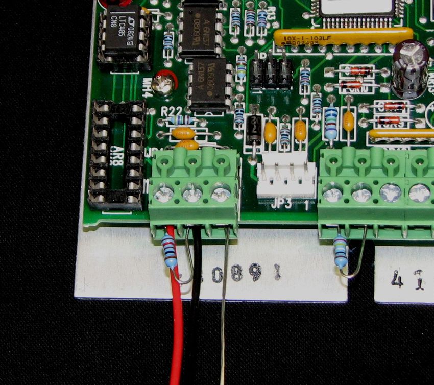
When the software is first started, it should prompt you to select the communications port to which the controller
is connected. It should then prompt you to enter an address number corresponding to a range of controller
addresses to search for. For new controllers, enter “98” [without the quotes] in the SEARCH ADDRESS RANGE
(indicated below), and then click the blue START button. For an existing controller, enter the address for that
controller. The software should then find and list the controller with its corresponding address (usually 98 for a
new controller) in the CONTROLLER LIST.
2. When a controller is being added to an existing network:
Before applying power to the new controller and adding the controller to the network, place a jumper between
JP2-1 and JP2-4. Also, if the new controller being added will be at the end of the network, make sure the new
controller is the only one with a terminating resistor across JP4-1 and JP4-2. See Multiple Controller Wiring (RS485)
Diagram for further details.
If the software is currently running the existing network, apply power to the new controller, and enter “99”
[without the quotes] in the SEARCH ADDRESS RANGE. Then click the CONTROLLER SEARCH button to search for the
new controller. When the jumper is added to the controller, it automatically assumes address 99. You can then
assign a new address (see Section 2.4.6) to that controller (make sure EEPROM WRITE ENABLED is checked; see
Section 2.4.1), remove power, remove the jumper, re-apply power, and communicate with the controller with the
newly assigned address. You can also use this method if you have inadvertently assigned the same address to two
or more controllers and need to reassign a new address.
202.1 ADDRESS
This is the address of the controller the software is currently communicating with. You can switch to a different
controller (if on a multi-controller network) by entering in an address from the CONTROLLER LIST.
CONTROLLER BEING
ADDRESSED BY PROGRAM
CONTROLLERS FOUND
When you have switched to a new controller, click the blue READ CONFIGURATION button (lower right corner of
the software); this will read the controller’s current settings into the software. Any changes made to the software
settings will only affect the controller whose address is shown in the ADDRESS box.
READ CONFIGURATION
212.2 CONTROL TEMPERATURE
Click the SELECT button in the CONTROL TEMPERATURE section to display the CONTROL TEMPERATURE options.
2.2.1 SET CONTROL TEMPERATURE BY:
The CONTROL TEMPERATURE can be set by various methods, as described below. The set temperature value can
be anywhere within the range set in the EXTERNAL SET RANGE.
a) COMPUTER: This enables the controller to send a fixed percentage of output power. The values that can be
entered in the SET TEMPERATURE box range from –5.11 to +5.11. This corresponds linearly to a fixed percentage
of power output where –5.11 equals –100% power and +5.11 equals +100% power. If you selected HEAT WP+1
and WP2- in the OUTPUT section (See Section 2.7.1), then -5.11 corresponds to full-power cooling. The value is
adjustable in 0.01 unit increments. See Section 2.5.1 for further details.
b) POTENTIOMETER ON INPUT 2: You can install a 5K ohm potentiometer on JP2 at pins 1, 2, and 3. The LOW
EXTERNAL SET RANGE temperature and the HIGH EXTERNAL SET RANGE temperatures are mapped to the full
counter-clockwise and full clockwise positions of the potentiometer, respectively. The set temperature scales
linearly between 0 and 5K ohm set by the potentiometer.
c) 0 TO 5VDC ON INPUT 2: The set temperature can be changed by varying the voltage (up to 5 Vdc) applied across
JP2-2(+) and JP2-1(-).
d) 0 TO 20mA ON INPUT 2: The set temperature can be controlled using a 20 mA current source. A 249 ohm resistor
should be applied across pins JP2-1 and JP2-2.
e) INPUT 2 TEMPERATURE + SET TEMPERATURE: This can be used to maintain a constant temperature difference
relative to the secondary thermistor. The secondary thermistor is installed at JP2-1, 2.
f) USE SET VALUE OF DISPLAY: The buttons on the optional, MP-2986 Keypad and Display Accessory are used for
changing the set point temperature. The display must be enabled in order to use this feature (see Section 2.4.2).
222.2.2 SET TEMPERATURE
Enter the desired set temperature value in degrees Celsius. This temperature must be within both the range of the
selected input sensor and the limits of low and high set ranges from the controller configuration setup. Also, verify
that the cooler is capable of safely operating at the entered set temperature. This is particularly important if you
are heating. While you can control to +100 °C using the standard thermistor, many TE devices are only rated for at
most 70 °C.
2.2.3 CONTROL SENSOR OFFSET and INPUT 2 OFFSET
The temperature sensors on input 1 (primary CONTROL SENSOR thermistor) and input 2 (secondary thermistor)
can be given separate offsets to correct for “errors” in the sensed temperature and the real temperature.
2.2.4 EXTERNAL SET RANGE
Use the HIGH EXTERNAL SET RANGE and LOW EXTERNAL SET RANGE to define the maximum and minimum
allowable set temperature values when using an external input for setting the control temperature.
2.2.5 READ INPUT 2 AS A TEMPERATURE
Enabling this feature configures input 2 the same as input 1. That is, the controller assumes a secondary thermistor
is installed. If you do not have a secondary thermistor installed, do not enable this feature; otherwise, the
controller will assume a sensor error exists.
If you are using two thermistors with the controller, they must have the same resistance versus
temperature characteristics. Also be sure that you have selected the correct sensor type. Otherwise a
dangerous condition could exist because the actual temperature could be higher or lower than the
temperature being interpreted by the controller.
2.3 TEMPERATURE SENSOR
The controller can accept several different types of negative-temperature coefficient thermistors. Available
options correspond to various temperature-resistance curves for thermistors as shown in “Temperature-Resistance
Curves” in the Appendix. Select the sensor type having the same temperature-resistance curve as the thermistor
you intend to use with the controller:
23a) TS-141 5K, control temperature range: -40 °C to +70 °C
b) TS-67, TS132 15K, control temperature range: -20 °C to +100 °C
c) TS-91 10K, control temperature range: -20 °C to +85 °C
d) TS-165 230K, control temperature range: +25 °C to +250 °C
e) TS-104 50K, control temperature range: 0 °C to 150 °C
f) MEAS 44031RC 10K, control temperature range: 0 °C to +70 °C
NOTE: Select TS-67, TS132 15K when using the supplied MP-3193 sensor or one of the other sensors listed in
Appendix C “Thermistor Styles for TC-36-25.” This will provide a control range of -20 °C to +100 °C. However,
remember that depending on the type of TE device you have, it might not be suitable for operation at
temperatures greater than 70 °C.
If you have an existing 10K Ohm thermistor, the TS-91 10K might be equivalent. The TS-91 10K is equivalent to the
10K ohm thermistor; curve “B” from Measurement Specialties, Inc.
Contact TE Technology if you need a sensor that uses a temperature scale different from the “TS-67, TS132 15K”.
If you are using two thermistors with the controller, they must have the same resistance versus
temperature characteristics. Also be sure that you have selected the correct sensor type. Otherwise a
dangerous condition could exist because the actual temperature could be higher or lower than the
temperature being interpreted by the controller.
2.4 CONTROLLER OPTIONS
2.4.1 EEPROM WRITE ENABLE
Upon a power-up or reset condition, the controller performs an initialization of all command variables that have
write commands. The controller transfers the last values stored in non-volatile memory (EEPROM) to
appropriately referenced static RAM locations. This action is performed so that the controller can run faster (RAM
is faster than ROM). This also allows the controller to run as a stand-alone controller, separate from the computer.
24You can also read