Introduction to the Android Graphics Pipeline
←
→
Page content transcription
If your browser does not render page correctly, please read the page content below
Introduction to the Android Graphics
                              Pipeline
Wissenschaftliche Arbeit zur Erlangung des Grades Bachelor of Science (B.Sc.)
     in Informatik an der Hochschule Karlsruhe - Technik und Wirtschaft

                             Mathias Garbe

                           Karlsruhe, im März 2014

           Betreuer:            Christian Meder
           Referent:            Prof. Dr. Holger Vogelsang
           Korreferent: Prof. Dr. Ulrich Bröckl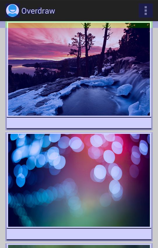
ii

Statement of Authorship
I hereby declare that this bachelor thesis has been written only by the undersigned
and without any assistance from third parties. Furthermore, I confirm that no sources
have been used in the preparation of this thesis other than those indicated in the
thesis itself.

Eidesstattliche Erklärung
Ich erkläre hiermit eidesstattlich, dass ich die vorliegende Bachelorarbeit selbständig
und ohne unerlaubte Hilfe verfasst, keine anderen als die angegebenen Quellen und Hil-
fsmittel benutzt und die den benutzten Quellen wörtlich oder inhaltlich entnommenen
Stellen als solche kenntlich gemacht habe.

Karlsruhe, March 17, 2014.
iii

Abstract
This bachelor thesis outlines the current state of the Android graphics pipeline. The
graphics pipeline is the part of Android which displays the user interface by using the
graphics processor.

This thesis begins by describing the principles of current graphics hardware. After-
wards the different hardware architectures of modern graphic processors are explained.

The main part of the thesis starts by looking at the history of the Android graph-
ics stack. An explanation of specific optimizations employed by Android and their
software implementation follows. The Android graphics pipeline is then explained
by demonstrating a sample application and tracing all drawing operations down the
pipeline to the actual rendering calls. Finally, current issues and problems like driver
support and overdraw are addressed.

Kurzfassung
Die vorliegende Bachelorarbeit erläutert den aktuellem Stand des Android-Grafikstacks.
Hierbei handelt es sich um den Teil von Android der Benutzeroberflächen mithilfe des
Grafikprozessors darstellt.

Zunächst wird der Aufbau und die Funktionsweise aktueller Grafikhardware erläutert.
Anschließend werden die verschiedenen Architekturen moderner Grafikprozessoren
beschrieben.

Im Hauptteil wird die Historie des Android-Grafikstacks betrachtet. Darauf aufbauend
werden konkrete Optimierungen und Implementierungsdetails von Teilen des Grafik-
stacks erklärt. Anhand eines Beispielprogrammes wird die Android-Grafikpipeline
untersucht und abschließend werden die Auswirkungen aktueller Probleme und The-
men wie Treibersupport und Overdraw getestet und bewertet.
iv

About the Source Code Listings
The source code listing in this thesis do not aim to be complete. To make the listings
more clear, imports and includes are omitted. In some cases, source code was
converted to pseudo-code. Likewise, no source code listing is intended to be compiled
or executed. All listings are solely for illustration purposes and need to be viewed in
their respective context.
v

Acknowledgments
During the course of this thesis, several persons have contributed to whom I owe my
gratitude.

Foremost, I wish to thank my supervisor, Christian Meder, for his encouragements
and keeping the thesis on track and within scope.

I wish to thank Tim and Mark for their continuous interest and input on the thesis.
Their inquiries have always helped me considering new approaches and generally
driving this thesis forward.

I wish to thank Benjamin, Erik, Siggy, Heike, Florian and Daniel for proof-reading and
correcting countless versions of this thesis and always making excellent suggestions
on how to improve it.

Last but not least, I would to express my sincere gratitude to Anika, my family and
all my friends, who have always motivated and supported me with encouragement
and consolation.
Contents

1. Introduction                                                                          1
   1.1. inovex GmbH . . . . . . . . . . . . . . . . . . . . . . . . . . . . . . .        1

2. Introduction to the Architecture of Modern Graphic Processors                         3
   2.1. GPU Vendors . . . . . . . . . . . . . . . . . . . . . . . . . . . . . . .        4
   2.2. Overview of the OpenGL Rendering Pipeline . . . . . . . . . . . . . .            5
        2.2.1. Vertex Generation . . . . . . . . . . . . . . . . . . . . . . . .         6
        2.2.2. Vertex Processing . . . . . . . . . . . . . . . . . . . . . . . . .       6
        2.2.3. Primitive Generation . . . . . . . . . . . . . . . . . . . . . . .        6
        2.2.4. Primitive Processing . . . . . . . . . . . . . . . . . . . . . . .        7
        2.2.5. Primitive Assembly and Fragment Generation . . . . . . . . .              7
        2.2.6. Fragment Shading       . . . . . . . . . . . . . . . . . . . . . . . .    8
        2.2.7. Pixel Operations . . . . . . . . . . . . . . . . . . . . . . . . .        9
        2.2.8. Framebuffer . . . . . . . . . . . . . . . . . . . . . . . . . . . .       9
   2.3. Pipeline Variants . . . . . . . . . . . . . . . . . . . . . . . . . . . . .      9
        2.3.1. Immediate Mode Renderer . . . . . . . . . . . . . . . . . . . .          10
        2.3.2. Tiling-Based Renderer . . . . . . . . . . . . . . . . . . . . . .        11
   2.4. Driver and Command Processor . . . . . . . . . . . . . . . . . . . . .          13
   2.5. Memory Architecture and Limitations . . . . . . . . . . . . . . . . . .         13
   2.6. Shader Architecture and Limitations . . . . . . . . . . . . . . . . . .         14
   2.7. Render Output Units . . . . . . . . . . . . . . . . . . . . . . . . . . .       15

3. Android Graphics Architecture                                                        17
   3.1. Hardware Accelerated UI Rendering . . . . . . . . . . . . . . . . . . .         18
        3.1.1. Asset Atlas Texture . . . . . . . . . . . . . . . . . . . . . . . .      18

                                           vi
Contents vii
3.1.2. Display Lists . . . . . . . . . . . . . . . . . . . . . . . . . . . 20
3.1.3. Merging of Operations . . . . . . . . . . . . . . . . . . . . . . 22
3.1.4. Software VSync . . . . . . . . . . . . . . . . . . . . . . . . . . 27
3.1.5. Triple Buffering . . . . . . . . . . . . . . . . . . . . . . . . . . 27
3.2. Rendering an example application . . . . . . . . . . . . . . . . . . . . 28
3.2.1. Activity Start . . . . . . . . . . . . . . . . . . . . . . . . . . . 29
3.2.2. Root View . . . . . . . . . . . . . . . . . . . . . . . . . . . . . 29
3.2.3. HardwareRenderer . . . . . . . . . . . . . . . . . . . . . . . . 32
3.2.4. View, ViewGroup and Layouts . . . . . . . . . . . . . . . . . . 33
3.2.5. TextView . . . . . . . . . . . . . . . . . . . . . . . . . . . . . 37
3.2.6. Button . . . . . . . . . . . . . . . . . . . . . . . . . . . . . . . 38
3.2.7. Choreographer . . . . . . . . . . . . . . . . . . . . . . . . . . 38
3.2.8. GLES20Canvas . . . . . . . . . . . . . . . . . . . . . . . . . . 38
3.2.9. Surface . . . . . . . . . . . . . . . . . . . . . . . . . . . . . . . 40
3.2.10. OpenGLRenderer . . . . . . . . . . . . . . . . . . . . . . . . . 40
3.2.11. DisplayListRenderer . . . . . . . . . . . . . . . . . . . . . . . 43
3.2.12. DeferredDisplayList . . . . . . . . . . . . . . . . . . . . . . . . 44
3.2.13. DisplayListOp . . . . . . . . . . . . . . . . . . . . . . . . . . . 45
3.2.13.1. DrawTextOp . . . . . . . . . . . . . . . . . . . . . . 46
3.2.13.2. DrawPatchOp . . . . . . . . . . . . . . . . . . . . . . 47
3.2.13.3. DrawDisplayListOp . . . . . . . . . . . . . . . . . . 49
3.2.14. FontRenderer . . . . . . . . . . . . . . . . . . . . . . . . . . . 50
3.2.15. SurfaceFlinger . . . . . . . . . . . . . . . . . . . . . . . . . . . 51
3.2.16. Summary . . . . . . . . . . . . . . . . . . . . . . . . . . . . . 51
3.2.17. Code Quality . . . . . . . . . . . . . . . . . . . . . . . . . . . 52
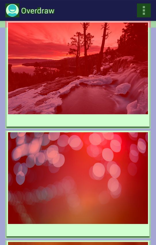
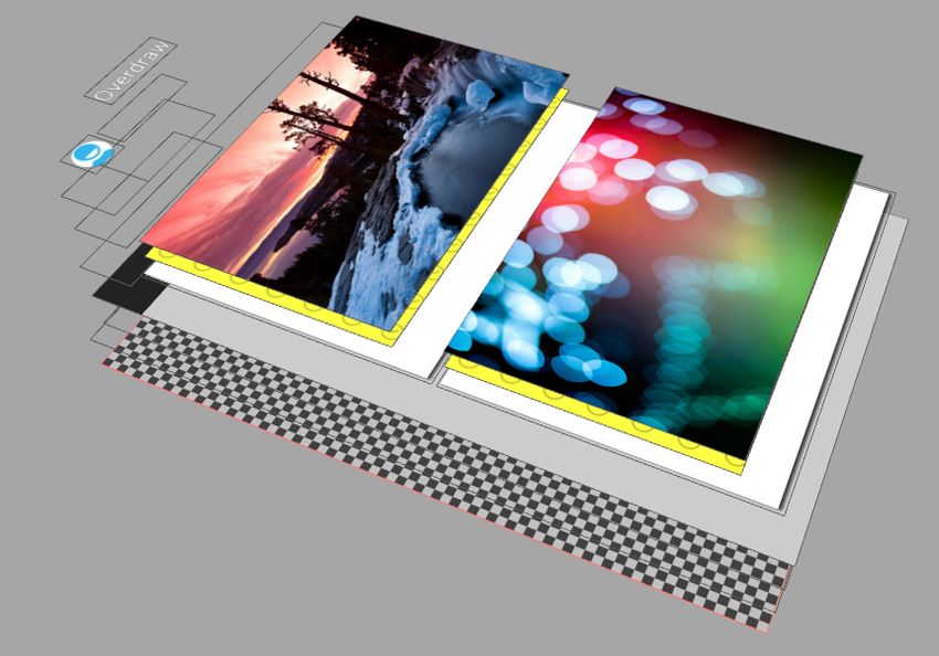
3.3. Overdraw . . . . . . . . . . . . . . . . . . . . . . . . . . . . . . . . . 52
3.4. Mobile Drivers and Vendor Tools . . . . . . . . . . . . . . . . . . . . 56
4. Conclusion and Outlook 59
A. Display list for the example view 60
B. OpenGL commands for the example view 63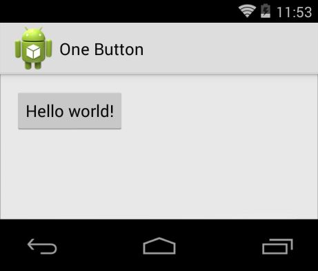
Contents                   viii

C. Overdraw measurements   69

Bibliography               73

Glossary                   79
1. Introduction

The Android operating system has a wide base of users and application developers.
Android’s Application Programming Interface (API) for writing applications is well
documented and many tutorials are available on the web.

Unfortunately, documentation of the actual Android operating system is scarce. The
inner workings of the graphics pipeline in particular are only ever mentioned by Google
employees in blog posts and on conference talks. This thesis aims to provide a basic
overview of the graphics pipeline.

This thesis is targeted at interested developers with prior knowledge of the Android
framework. Readers can also use the official Android framework documentation1 and
the Android Open Source Project (AOSP) website2 as a reference.

The analysis and breakdown of the Android source code is based on Android 4.4.2 r2
(android-4.4.2_r23 ). All source code listings are also based on this Android version.

1.1. inovex GmbH

inovex GmbH4 was founded in 1999 in Pforzheim, Germany. Since then, it has been
managed by its sole owner and founder, Stephan Müller. inovex GmbH has about 13
employees, with offices in Pforzheim, Karlsruhe, Cologne and Munich.

The company is focused on contract work and is divided into multiple lines of business,
which are Application Development, Business Intelligence, IT Engineering and the
 1
   http://developer.android.com/
 2
   http://source.android.com/
 3
   http://source.android.com/source/build-numbers.html
 4
   http://www.inovex.de/

                                          1
1.1. inovex GmbH 2 inovex Academy. This thesis was written with the Android embedded development team, which is a part of the Application Development line of business. Lectures at symposiums and published works in professional journals also have a high significance for its public image and are highly encouraged. The Droidcon and the Mobile Tech Conference are just two examples where inovex employees appear as regular speakers.
2. Introduction to the Architecture of
       Modern Graphic Processors

Today’s Graphics Processing Units (GPUs) differ greatly from early ones. While these
typically only supported accelerated 2D drawing and bitmap blitting, modern GPUs
have a much broader field of application. These early GPUs had hardware support
for basic 2D drawing and animations. In practice this is copying image data from a
bitmap to the framebuffer at a specific location, scale and rotation. Quite surprisingly,
these early GPUs also introduced the hardware cursor to unburden the operating
system and Central Processing Unit (CPU). This meant a huge boost in performance
for this time and made non-text-based games possible.

Modern GPUs still have all these basic 2D hardware features hidden somewhere
on the chip itself (the die) [Gie11a], but their main focus has shifted quite heavily.
Nowadays, GPUs provide accelerated 3D rendering and hardware video decoding.
Recently, General-Purpose computing on Graphics Processing Units (GPGPU) also
got popular. This is possible because a modern GPU is basically a huge number of
parallel floating point processing units bundled together. After all, 3D rendering in
its purest form is only matrix and vector calculus.

These processing units themselves have a Single Instruction Multiple Data (SIMD)
like instruction set which allows vector calculation using very few instruction cycles.
For example, the multiplication of ~a with ~b followed by the addition with ~c

                                      (~a × ~b) + ~c

can be performed in one cycle with the Multiply-Add instruction (MAD) instruction.

                                            3
2.1. GPU Vendors 4
Modern CPUs do have comparable features, with the latest addon being the Advanced
Vector Extension (AVX) [Int08] instruction set. Nevertheless, they are still much slower
because of the simple fact that their processor count is much lower.
To fully understand the Android rendering optimizations and pipeline a low-level
understanding of GPUs graphics pipeline is necessary. Because no vendor is very
specific about the internals of their GPU architecture, one has to sift through marketing
presentations, blog posts and white papers to find the relevant pieces of information.
Therefore, most of the information presented here is to be considered a simplification
of what the hardware actually does.
2.1. GPU Vendors
Vendor 2013
Intel 62.0%
AMD 21.9%
Nvidia 16.1%
Table 2.1.: Market Share of desktop GPUs. [Jon14a]
The traditional desktop market is seemingly dominated by Intel, but this is due to
the fact that since 2010 every new Intel CPU has an integrated GPU called Intel HD
Graphics. While these GPUs can handle simple 3D rendering, more complex scenes
and computations still need a discrete GPU. AMD’s market share is influenced by
the fact that Bitcoin miners prefer the AMD Radeon GPUs due to a much faster hash
calculation compared to Nvidia’s GeForce series. [Kha14]
Vendor 2013
Qualcomm 32.3%
Imagination Technologies 37.6%
ARM 18.4%
Vivante 9.8%
Nvidia 1.4%
DMP 0.5%
Table 2.2.: Market Share of mobile GPUs. [Jon14b]2.2. Overview of the OpenGL Rendering Pipeline 5
The mobile market is more diverse and all of the vendors sell their GPUs as Intellectual
Property (IP) Cores, which will be bundled with other components like the CPU and
main memory on a System on a Chip (SOC). Qualcomm’s Adreno, which was originally
bought from AMD, and Imagination Technologie’s PowerVR are the biggest players
in the market to date. Imagination Technologies owes its big market share to Apple,
as all their iOS devices are powered by an PowerVR GPU.
Quallcomm Adreno is currently the only GPU that is being used with Windows Phone
8 devices. Nvidias Tegra is still not very popular, with the newest devices being Nvidia
Shield and Nvidia Note 7 from 2013.
2.2. Overview of the OpenGL Rendering Pipeline
In order to render objects to the screen, the Open Graphics Library (OpenGL) defines
a sequence of steps. This is called the OpenGL Rendering Pipeline (Figure 2.1). This
pipeline is described in a general, low level way here.
Tessellation
Vertex Control Evaluation Geometry Transform
Tessellation
Shader Shader Shader Shader Feedback
Pixel Fragment
Framebuffer Rasterizer Clipping
Operations Shader
Fig. 2.1.: Simplified OpenGL Rendering Pipeline overview. Programmable stages are colored
in blue and optional stages are marked with dashes. (Image based on [Ope13d])
It is important to mention that the hardware implementation can differ greatly and
is not defined by the OpenGL API. Neither is the architecture of the renderer (sec-
tion 2.3) defined, nor whether it implements optimizations such as an Early-Z (see
glossary), Hierarchical Z-Buffer (Hi-Z, see glossary) or Hidden Surface Removal (HSR,
see glossary) pass. But regardless of how the hardware is designed and what kind of
optimizations are used, it has to make sure that the output is exactly the same as the
OpenGL standard dictates.2.2. Overview of the OpenGL Rendering Pipeline 6 2.2.1. Vertex Generation Graphics APIs like OpenGL or DirectX store their geometry data as a collection of primitives like triangles or quads. Each of these primitives is defined by a set of vertices. To render these, the API provides a stream of Vertex Attributes for the Vertex Generation stage. These attributes typically contain the 3D coordinates (in model space), surface color and a normal vector. [FH08b, p. 52] 2.2.2. Vertex Processing After the API submitted its geometry stream to the hardware, the vertex process- ing stage is executed. For each vertex, which is composed of a series of Vertex Attributes [Ope13f], the Vertex Shader (VS) is executed. The VS is the first pro- grammable stage in the rendering pipeline and for every processed input vertex it must output an vertex. Typically, this is where the Model-View-Projection Matrix is applied to the vertex, which transforms its position from model coordinates to screen coordinates. The color and normal information of the vertex are stored for processing in the Fragment Shading stage. 2.2.3. Primitive Generation Since OpenGL version 4.0, the vertices are then passed to the programmable tessel- lation stage. The purpose of the Tessellation Control Shader (TCS) is to subdivide primitives into patches, thus increasing the detail of the surface. It is also responsible for ensuring that these new patches do not have gaps and breaks, which can occur during subdivision. The Tessellation Evaluation Shader (TES) is responsible for the calculation of new vertex attributes for the position, color and normal vector of the newly generated primitives. [Ope13e] If no tessellation stage is defined, the output from the vertex shader is passed as a primitive to the next stage.
2.2. Overview of the OpenGL Rendering Pipeline                                          7

2.2.4. Primitive Processing

Each primitive is handed to the Geometry Shader (GS), which outputs zero or more
primitives. The type of input and output primitives does not have to match - the
GS could output a list of triangles generated from a list of points. A typical use-case
for the GS is animating of a particle system, or creating of billboards from a list of
points. [Ope13b]

If no geometry shader is defined, the primitives are directly passed to the next stage.

This is also the stage where Transform Feedback (also called Stream Out) happens:
the pipeline is writes all primitives to the Transform Feedback Buffer, which can
then be cached and rendered again. This is useful when a TCS or GS does heavy
computations, like tessellating a model.

When animating particles, this can also be used to save the current state of all particles
so that the application can read the current positions. In the next frame, this new
state is passed to the GS which in turn updates all particles.

2.2.5. Primitive Assembly and Fragment Generation

All primitives need to broken down into individual points, lines or triangles. The Primi-
tive Assembly converts Quads and Triangle Strips to triangles, which are then passed to
the rasterizer. All primitives can also be discarded with the GL_RASTERIZER_DISCARD
option, which prevents the primitives from being rasterized. This can be used to
debug performance issues in the previous stages, but also to prevent rendering of
primitives generated with Transform Feedback. [Ope13c]

The primitives are handed to the Fragment Generation stage, also called “Rasterizer”,
which converts the primitive to a list of fragments which are passed to the Fragment
Shading stage. Before modern GPUs, rendering was commonly done in software with
a scanline algorithm. This rasterized the geometry line-by-line and than shaded each
pixel [Hec95]. While this was a good approach on general purpose hardware like the
CPU, it does not transform well to a hardware implementation.
2.2. Overview of the OpenGL Rendering Pipeline                                         8

Juan Pineda presents a hardware-friendly approach in [Pin88]. The basic idea is that
the distance to a line can be computed with a 2D dot product. In order to rasterize
a triangle, all candidate pixels (which can be determined with a bounding shape) are
tested against all three triangle edges. If the pixel is inside all edges, the pixel is
marked as inside and is handed to the fragment shading stage.

This can be further optimized and implemented in a parallel fashion. The AMD chip
inside the XBox360 uses 8 × 8 sized tiles, which are rasterized in parallel [AHH08,
p. 862]. Modern GPUs use another, more coarse tile rasterizer which precedes the
main one, in order avoid wasted work on the pixel level. This rasterizer only tells the
fine rasterizer if a tile is potentially covered by a triangle [Gie11d]. High-performance
GPUs employ multiple of these rasterizer combinations.

2.2.6. Fragment Shading

All visible fragments are passed to the Fragment Shader (FS). The main responsibility
of the programmable FS is to write an output color for the processed fragment, but
it can also write output depth and even multiple colors to multiple buffers. The
color can be calculated in a number of ways, incorporating textures, light, global
illumination and other factors. Per-vertex attributes, which are passed from the VS,
are interpolated to the fragment position. Also, the FS has access to the discard
keyword, which can be used to discard a pixel, preventing it from proceeding further
down the pipeline [Ope13a].

Each fragment is independent from another, they can be executed with the FS in
parallel. Modern GPUs have a number of shader cores dedicated to this. Fragments
are bundled as multiple batches and then processed by the shader cores. As these
cores operate in a lockstep fashion, dynamic branches in shaders are expensive. If
only one core takes a branch, all other shader cores need to execute the branch too,
even though they will discard the result anyway [Gie11e].
2.3. Pipeline Variants                                                                9

2.2.7. Pixel Operations

After each primitive is processed by the FS, they have to be merged into a final image.
This stage is also responsible for blending and pixel testing, which needs to happen in
the same order as the application sends the primitives. Any hardware optimizations
of the drawing order need to be reverted here. Both blending and pixel testing are
relatively cheap computations, but have a high bandwidth requirement as they need
to both read from and write to the render target.

Blending happens in a fixed-function block which is not yet programmable but only
configurable (section 2.7). To blend two pixels together, the current color must first
be read from the render target. According to the configuration, the color is blended
with the process fragment and written back to memory. This is an important step
when rendering translucent surfaces. Pixel tests include stencil, scissor and depth
testing, which can be turned on or off by the graphics API.

2.2.8. Framebuffer

The resulting image is written to a framebuffer, which can in turn be swapped to the
display or used as a new texture. Figure 2.2 shows an example of an operation in the
graphics pipeline.

2.3. Pipeline Variants

Currently, there are two pipeline variants, which are both very old and date back to the
same time periods of early GPUs. Vodoo, Nvidia and ATI started out with a straight-
forward and easy to implement Immediate Mode Renderer (IMR), and PowerVR used
the more complex Tile-Based Renderer (TBR) approach. Nvidia and ATI/AMD still
use the immediate-mode approach and are the main vendors for desktop GPUs. On
mobile chipsets, the tile-based approach is more common, due to power, heat and space
constraints. The Nvidia Tegra is the only mobile chipset that uses immediate-mode
rendering.
2.3. Pipeline Variants                                                                      10

      (a)                 (b)                  (c)              (d)                (e)

Fig. 2.2.: Example of an operation trough the Graphics Pipeline [FH08a, p. 21]

  a) Six vertices (v0-v5 ) from the Vertex Generation stage, defining two triangles.

  b) After Vertex Processing and Primitive Generation the two triangle primitives (p0 and
     p1 ) are projected and transformed to screen-space coordinates.

   c) Fragment Generation produces two sets of fragments from the triangles.

  d) Each fragment is shaded in the Fragment Shading stage, according to the associated
     fragment shader.

   e) Fragments are combined in the pixel operations stage and the final image is transferred
      to the framebuffer. Triangle p1 occludes p0 as it is nearer to the camera.

2.3.1. Immediate Mode Renderer

Traditionally, a IMR renders every polygon without any knowledge of the scene. This
is because old graphic APIs such as OpenGL were originally designed as an immediate
mode API, where every primitive was rendered in order of submission. This has caused
a huge waste of processing power due to Overdraw (see glossary). Newer versions
of OpenGL phased out immediate mode and the OpenGL 4 Core Profile deprecated
all immediate mode functions. Optimizations such as Early-Z help with reducing
Overdraw, but are only as good as the application geometry ordering. Figure 2.3 gives
a simplified overview of the pipeline of a traditional IMR.

    Vertex        Primitive        Early             Fragment       Late           Pixel
  Processing      Rasterizer      Visibility          Shading     Visibility     Operations
                                                                                                 Memory

  Geometry                                           Texture          Depth        Frame
    Data                                              Data            Buffer       Buffer

 Fig. 2.3.: Simplified Immediate Mode Renderer Pipeline (Image based on [Gan13, p. 5])
2.3. Pipeline Variants 11 Despite the name, tiling is not absent from IMRs. Modern GPUs use multiple raster- izers, where Nvidia uses up to four [Pur10, p. 8] and AMD up to two [Fow10, p. 5]. With Hi-Z whole tiles can be rejected before they arrive in the fragment shading stage of the pipeline. Finally, fragment shaders are also working in so called shading blocks, which are processed in parallel [Fat10, p. 27]. It is to be assumed that these shading blocks are orderded in a specific way to maximize memory page coherency [Gie11f]. 2.3.2. Tiling-Based Renderer Mobile GPUs must balance performance and power consumption, which is why they will never be as powerful as desktop GPUs. One major power consumer is the memory, as it is usually shared with the CPU. The memory also has a high latency as it is not located on the chip itself but needs to be addressed over a slow memory bus, which is shared with other peripherals such as the camera or wireless connectivity. Power consumption and latency also increases with the length of this memory bus. Especially in the pixel operations stage, the renderer needs to read from and write to the framebuffer. For example when using transparency, the old pixel value needs to be fetched from the framebuffer in order to be blended with the partially transparent pixel, and only then can the resulting pixel be written back to the framebuffer. To improve performance and reduce power usage, most mobile GPUs use a tile-based rendering approach, with the famous exception of the Nvidia Tegra, which is still an IMR. These TBRs move the frame and depth buffer to high speed on-chip memory, which is much closer to the GPU and therefore much less power is needed. As the on-chip memory takes a lot of space on the chip itself, it cannot be the full size of the framebuffer and must be smaller. This tile buffer is usually only a few pixels big [Mer12]. In order to render a scene, the TBR first splits the scene into multiple equally-sized tiles and saves them to memory (called the “frame data”). The OpenGL API is designed as an immediate-mode renderer, it specifies primitives to be drawn with the current state. So for this tile-based approach to work, the GPU needs knowledge of all objects to be drawn in the current frame. This is also the reason why calling
2.3. Pipeline Variants                                                                   12

    Vertex                          Primitive    Visibility    Fragment         Pixel
                   Tiling
  Processing                        Rasterizer     Test         Shading       Operations

                                                                                              On-Chip
                                                  Depth
                                                                              Tile Buffer
                                                  Buffer

                                                                                              Memory
  Geometry                  Frame                               Texture         Frame
    Data                     Data                                Data           Buffer

   Fig. 2.4.: Simplified Tiling-Based Renderer Pipeline (Image based on [Gan13, p. 7])

glClear() seems to take much longer than actual draw calls, because only when the
driver can be certain that a frame is complete it can issue the rendering commands
to the hardware. The GPU can now render each of these tiles, one at a time, into
the on-chip tile buffer. As the tiles are completely independent from each other, this
operation scales almost linearly and GPUs can employ multiple renderers to improve
performance. After a tile is rendered completely, the contents of the color buffer are
copied back to the framebuffer. Figure 2.4 gives an overview of the pipeline of a TBR.
In addition to the tile buffer, the visibility test on a TBR also employs an on-chip
depth buffer [Gan13].

As seen in the effort of reverse engineering of the vendor driver and implementation of
a free driver for the Adreno chipset family called freedreno, the tiling effort is usually
not handled in hardware but in software in the driver itself [Fre13a].

The term “Tiling-Based Deferred Renderer” (TBDR) is coined by the Imagination
Technologies PowerVR GPU Series. This is mostly a marketing strategy, as it is
basically a regular TBR with added HSR. This is basically a per-tile Z-Buffer, which
is located on very fast memory. The geometry is rasterized per tile (without shading)
and written to this Z-Buffer. It is used to discard pixels that are occluded. Since the
PowerVR MBX Series [Ima09, pp. 6-7], rasterization of tiles only uses one processing
cycle per processed line. On a 32 × 32 tile buffer such a line is 32 pixels wide. This has
the added benefit of free horizontal and vertical clipping, as HSR is only performed
on on-screen pixels.
2.4. Driver and Command Processor 13 2.4. Driver and Command Processor The GPU driver implements the graphics API and serves as an abstraction layer for the hardware. The driver translates the API calls into a stream of commands which is sent to the GPUs command processor. These commands are stored in a ring buffer, from which the command processor is reading. They usually set registers or trigger rendering commands. Some modern GPUs have separate command processors for 2D and 3D rendering. Changing the rendering state of the GPU is tricky. On nearly every state change, the GPU is forced to completely flush all work that is still being processed in the pipeline, which can mean a major slowdown of the rendering. For example, when changing the current texture or shader, the driver needs to wait for all current processing work to complete in order to not interfere with the rendering result. Examples of such commands can be seen in the free driver for the Qualcomm Adreno, freedreno [Fre13b]. 2.5. Memory Architecture and Limitations Modern GPUs employ a different memory subsystem than modern desktop CPUs. The memory architecture of a GPU favors bandwidth over latency, which means really fast transfers with high waiting periods. This trade-off is a result of GPUs dealing with increasingly higher resolutions of textures and displays. To mitigate the high latency, modern GPUs employ a series of caches. The high bandwidth also comes with a big hit in power draw of the memory bus. A first-generation Intel Core i7 has a peak bandwidth of almost 20 GB/s with a memory latency of 47 ns. Dividing this latency by the clock rate of 2.93 GHz results in a cache miss penalty of about 140 cycles. The Geforce GTX 480 on the other hand has a peak bandwidth of 180 GB/s, a shader clock rate of 1.5 GHz and a memory latency of 400 to 800 cycles [Ren11, p. 11]. This is a bit more than 4× the average
2.6. Shader Architecture and Limitations                                          14

memory latency with almost half the clock rate of an Core i7. The resulting cache
miss penalty is therefore many times higher [Gie11a].

Many mobile devices and some low-cost desktop and notebook devices feature so
called unified or shared memory. In this scenario, the GPU has no discrete memory
to work with but is allocated a part of the system memory. The rest of the system
is therefore sharing the already small, available memory bandwidth with the GPU.
This is more noticeable on mobile devices. The Nexus 7 (2013) has a peak bandwidth
of 13 GBit/s with a resolution of 1920 × 1200 pixels. These pixels are stored inside
the framebuffer in a RGB565 configuration (16 bit per pixel). This alone results in a
2.2 GBit/s bandwidth need to achieve 60 frames per seconds if every pixel is rendered
once. Overdraw, texture access and render targets are also putting more stress on the
memory bus.

2.6. Shader Architecture and Limitations

The first programmable hardware stages or shader units used a assembly-like program-
ming language. The vertex and fragment shader used different hardware architectures
and therefore different subsets of said programming language. Each hardware archi-
tecture had different performance trade-offs, with vertex and texture caching as an
example.

After the introduction of high-level shader languages like the OpenGL Shading Lan-
guage (GLSL) or the DirectX counterpart High-Level Shading Language (HLSL),
which was developed alongside with Nvidias C for Graphics (Cg), the unified shader
model was introduced. This unified the vertex and fragment shader hardware designs
into one design, which is now used for both shader types.

The shader hardware consists basically of fast Arithmetic Logic Units (ALU) built
around a Floating Multiply-Accumulate (FMAC) unit. There is also special hardware
for common used mathematical functions (for example the square root, trigonometric
and logarithmic functions). The shader units are optimized for high throughput and
are running a high number of threads, which run the same shader code in parallel. Due
2.7. Render Output Units                                                                15

to the architecture the hardware is not particularly good at branching code, especially
if these branches are not coherent. In some cases its even possible that a batch of
threads execute unnecessary branches and discard the results, only because one thread
needs to execute the branch.

With the unified shader model, vertex, fragment and other shaders have virtually no
hardware differences, but the used shader language may impose artificial limitations
which are enforced in software. AMD is using a SIMD architecture that is wide enough
for a four component vector, which is implied by most shading languages. Nvidia uses
scalar instructions [Gie11b].

Another reason to run the shader in batches is texture access. Memory access is
optimized for high bandwidth with the drawback of high latency (section 2.5). If a
shader asks for a texture sample, it does so in bigger blocks. Texture sample requests
of 16 to 64 pixels per thread are now being used by the major vendors. While waiting
for the hardware to fetch the texture samples, the shader unit will pause execution
and switch to another shader batch if there is one available. Most vendors also employ
a two-level texture cache to mitigate the huge memory latency and exploit the fact
that most texture access is bilinearly sampled and uses four texture pixels. Every
texture cache hit is a huge performance improvement because the hardware does not
have to fetch a new texture block [Gie11c].

2.7. Render Output Units

The Render Output Unit (ROP), also called Raster Operations Pipeline on occasion,
is the final step in the rendering process. The name is purely historical, as it originates
from early 2D hardware accelerators, in which their main purpose was fast bitmap
blitting. It hat three inputs: the source image, a binary image mask and the destination
coordinates. The ROP first blitted the mask to the framebuffer at the destination
with an AND operation. Finally, the source image would be copied to the destination
with an OR operation. Nowadays, the binary image mask is replaced with an alpha
value, and the bitwise operations with a configurable blending function [Gie11f].
2.7. Render Output Units                                                          16

On a TBR, blending and other pixel operations are very fast, because the required
buffers are also on the on-chip memory and only need to be flushed to the framebuffer
when all operations are completed.
3. Android Graphics Architecture
Traditionally, all android views were drawn to a bitmap in software using a software
renderer called Skia. These bitmaps were uploaded to the GPU and all views were
composed in hardware since before the first Android release. This allowed effects
like scrolling, pop-ups and fading to be fast, as these frequently used effects are
implemented in the compositing stage of the rendering pipeline and happened in
hardware [Hac11].
Nevertheless, compared to an iOS device, Android felt much slower. This was due
to the fact that usually the default browsers of both platforms were used to compare
performance. The iOS browser uses a tiled approach, which renders the webpage into
smaller tiles. This makes zooming and panning much smoother. Android rendered the
page directly to the screen, which was done to eliminate artifacts when zooming. But
this made rendering and zooming more complex and therefore slower. As of Android
3.0 the stock browser also uses a tiled rendering approach.
Starting with Android 3.0 Honeycomb (API Level 11), hardware accelerated UI render-
ing was introduced. With the help of OpenGL, Android could now renderer frequently
used canvas operations with the GPU. This still needed manual enabling in the
AndroidManifest file and not all canvas operations were supported, but the founda-
tions for a faster rendering system were laid. Unsupported operations included the
canvas methods drawPicture, drawTextOnPath and drawVertices. With Android
4.0 Ice Cream Sandwich (ICS, API Level 14) the opt-in hardware acceleration became
opt-out, an application targeted for ICS or later now needs to specifically disable the
acceleration via the manifest [Hac11]. Using a unsupported canvas operation will turn
the hardware acceleration off. Even with Android 4.4 KitKat (API Level 19) not all
canvas operations are supported [And13a].
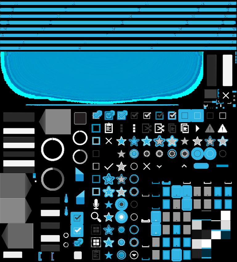
173.1. Hardware Accelerated UI Rendering 18 Using OpenGL to render the UI is merely a trade-off between rendering speed and memory usage. Currently, only initializing an OpenGL context in a process can cost up to 8 MB memory usage. This can be a huge hit to the memory footprint of the application. Therefore, the Android engineers decided to specifically disable hardware acceleration on most system processes such as the navigation bar and status bar. To reduce stress on the GPU and memory system only invalidated parts of the UI are redrawn. This is implemented with the use of clipping rectangles. The use of hardware overlays further reduces bandwidth use, as they do not have to composited on the screen. If the number of available overlays are not sufficient, framebuffer objects are used which are essentially textures. These have to be composited on the screen, meaning a copy of the contents to the framebuffer. 3.1. Hardware Accelerated UI Rendering As the Android rendering pipeline has grown for several years now, the codebase itself is very big and is not explained in depth here. Nevertheless, all critical code paths in all major components are explained that will be used when Android renders a standard application. Rendering is only a small part of the applications execution and only possible in conjunction with the window and input systems, which are not explained here. 3.1.1. Asset Atlas Texture The Android start-up process Zygote (see glossary) always keeps a number of assets preloaded which are shared with all processes. These assets are containing frequently used NinePatches (see glossary) and images for the standard framework widgets. But for every asset used by a process, there exists a GPU copy as a texture. Starting with Android 4.4 KitKat, these frequently used assets are packed into a texture atlas, uploaded to the GPU and shared between all processes at system start. Figure 3.1 shows an asset atlas texture generated on a Nexus 7, containing all frequently used framework widget assets. It is important to note, that the NinePatches in the
3.1. Hardware Accelerated UI Rendering                                                   19

asset texture do not feature the typical borders which indicate the layout and padding
areas. The original asset file is still used on system start to parse these areas, but it
is not used for rendering.

The SystemServer, started by Zygote
at boot-time, initializes and starts the
AssetAtlasService1 . On the first boot
or after a system update, this service
brute-forces trough all possible atlas
configurations and looks for the best
one, which maximizes the number of
assets packed and minimizes the size
of the texture. This configuration is
written to /data/system/framework_
atlas.config and contains the chosen
algorithm, dimensions, whether rota-
tions are allowed and whether padding
                                              Fig. 3.1.: A sample texture atlas generated on
has been added. All used assets are first                a Nexus 7 [And13d]
sorted by width and height. This continues until all textures have been packed into
the atlas.

The Atlas2 is responsible for packing the assets. It starts with an empty atlas texture,
divided into a single cell. After placing the first asset, the remaining space is divided
into two new rectangular cells. Depending on the algorithm used, this split can either
be horizontal or vertical. The next asset texture is added in the first cell that is large
enough to fit. This now occupied cell will be split again and the next asset is processed.
The AssetAtlasService is using multiple threads for this process. The algorithm
producing the best fitting atlas will then be saved to the configuration file for future
usage. The internal implementation is based on a linked list for performance reasons,
but the algorithm itself is best represented as a simple binary tree.

 1
     File location: frameworks/base/services/java/com/android/server/AssetAtlasService.java
 2
     File location: frameworks/base/graphics/java/android/graphics/Atlas.java
3.1. Hardware Accelerated UI Rendering 20 When booting the system, the atlas configuration file is read from disk and the Atlas will recompute the asset atlas texture with the supplied parameters. A RGBA8888 graphic buffer is allocated as the asset atlas texture and all assets are rendered onto it via the use of a temporary Skia bitmap. This asset atlas texture is valid for the lifetime of the AssetAtlasService, only being deallocated when the system itself is shutting down. When a new process is started, its HardwareRenderer queries the AssetAtlasService for this texture. Every time the renderer needs to draw a bitmap it checks the atlas first. When the atlas contains the requested bitmap, it will be used in rendering [And13d]. 3.1.2. Display Lists In the world of the android graphics pipeline, a display list is a sequence of graphics commands needed to be executed to render a specific view. These commands are a mixture of statements that can be directly mapped to OpenGL commands, such as translating and setting up clipping rectangles, and more complex commands such as DrawText and DrawPatch. These need a more complex set of OpenGL commands. Listing 3.1 shows an example of a basic display list which renders a button, located at the origin pxy = (0, 0). The parent of the button is responsible for translating this origin to its actual position inside the view hierarchy, and then executing the buttons display list. In the example, the first step is to save the current translation matrix to the stack, so that it can be later restored. It then proceeds to draw the buttons NinePatch, followed by another save command. This is necessary because for the text to be drawn, a clipping rectangle is set up to the region that is affected by the text, and the origin is translated to the text position. The text is drawn and the original translation matrix is restored from stack.
3.1. Hardware Accelerated UI Rendering                                                21

  Save 3
  DrawPatch
  Save 3
  ClipRect 20.00, 4.00, 99.00, 44.00, 1
  Translate 20.00, 12.00
  DrawText 9, 18, 9, 0.00, 19.00, 0x17e898
  Restore
  RestoreToCount 0

             Listing 3.1: Example display list for rendering a Button [GH11]

Every view generates its own display list, recursively descending the view hierarchy.
If a view gets invalidated due to user input events or animations, the affected display
lists will be rebuilt and eventually redrawn. The root view is responsible for triggering
this rebuilding of the display lists after an invalidation.

Replaying an display list is much more efficient than executing the view’s onDraw()
method, as the display list lives on the native C++ side of the pipeline and is basically
just a huge sequence of drawing operations. The display lists are built around a canvas
(GLES20RecordingCanvas, subsection 3.2.8), which does not execute the drawing
operations but records them for later playback.

Fig. 3.2.: An example view hierarchy and the corresponding display list hierarchy [GH11]

For example, if View B (Figure 3.2) gets invalidated, only the DisplayList B needs
to be rebuild. This also means that only the display region that is affected by this
display list needs to be redrawn. Internally, this is done by setting up a clipping
3.1. Hardware Accelerated UI Rendering 22
rectangle and redrawing all display list that could possibly affect this rectangle. It is
possible for the GPU to reject pixels that are not inside the clipping region.
Android 4.3 introduced Display List Properties, which are used to prevent a com-
plete display list rebuild on specific invalidation changes. Changing a views position,
rotation, scale or transparency now results in a optimal invalidation, as the display
list does not need to be rebuild but only redrawn with the changed properties. The
Android documentation claims that no redrawing of the targeted view is needed3 , but
that only applies to execution to the views onDraw() method. The display list still
has to be replayed.
The display list itself is implemented in DisplayList4 , and the GLES20DisplayList5
is only a small abstraction layer build on top of the native display list and an instance of
a GLES20RecordingCanvas (subsection 3.2.8). This native display list in turn is only a
small wrapper around a DisplayListRenderer (subsection 3.2.11) and is responsible
for managing the display list properties. A transformation matrix is calculated from
these properties, which will be applied before the display list is replayed. Replaying
a display list is as simple as iterating over all display list operations and calling the
replay() method on it (Listing 3.2).
void DisplayList::replay(...) {
for (unsigned int i = 0; i < displayListOps.size(); i++) {
DisplayListOp *op = displayListOps[i];
op->replay(...);
}
}
Listing 3.2: Replaying a display list by iterating over all operations and calling replay()
3.1.3. Merging of Operations
Before Android 4.3, rendering operations of the UI were executed in the same order
the UI elements are added to the view hierarchy and therefore added to the resulting
3
http://developer.android.com/guide/topics/graphics/hardware-accel.html
4
File location: framework/base/libs/hwui/DisplayList.cpp
5
File location: framework/base/core/java/android/view/GLES20DisplayList.java3.1. Hardware Accelerated UI Rendering 23
display list. This can result in the worst case scenario for GPUs, as they must switch
state for every element. For example, when drawing two buttons, the GPU needs to
draw the NinePatch and text for the first button, and then the same for the second
button, resulting in at least 3 state changes (section 2.4).
With the introduction of reordering,
Android can now minimize these state
changes by ordering all drawing oper-
ations by their type. As seen in Fig-
ure 3.3, a naive approach to reordering
is not sufficient. Drawing all text el-
ements and then the bitmap (or the
other way around) does not result in
the same final image as it would with-
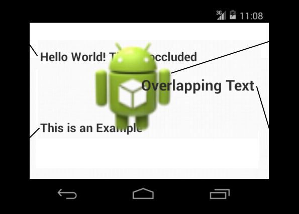
Fig. 3.3.: Example Activity with overlapping
out reordering. text elements and one drawable.
In order to correctly render the Activity in Figure 3.3, text elements A and B have to
be drawn first, followed by the bitmap C, followed by the text element D. The first
two text elements can be merged into one operation, but the text element D cannot,
as it would be overlapped by bitmap C. Regardless of the merging, the FontRenderer
will be further optimizing this case (subsection 3.2.14).
To further reduce the drawing time needed for a view, most operations can be
merged after they have been reordered. Listing 3.3 shows a simplified algorithm
Android uses to reorder and merge drawing operations. This happens in the so-called
DeferredDisplayList6 , because the execution of the drawing operations does not
happen in order, but is deferred until all operations have been analyzed, reordered
and merged. Because every display list operation is responsible for drawing itself,
an operation that supports the merging of multiple operations with the same type
must be able to draw multiple, different operations in one call. Not every operation
is capable of merging, so some can only be reordered.
To merge operations in an application’s DisplayList each operation is added to
the deferred display list by calling addDrawOp(DrawOp). The drawing operation is
6
File location: frameworks/base/libs/hwui/DeferredDisplayList.cpp3.1. Hardware Accelerated UI Rendering 24
Fig. 3.4.: The OpenGLRenderer creates a DeferredDisplayList and the original
DisplayList is adding every operation to the new deferred one. The deferred
display list then being flushed.
asked to supply the batchId, which indicates the type of the operation, and the
mergeId by calling DrawOp.onDefer(...) (subsection 3.2.13). Possible batchIds
include OpBatch_Patch for a NinePatch and OpBatch_Text for a normal text element,
which are defined as an enum (enum OpBatchId7 ). The mergeId is determined by
each DrawOp itself, and is used to decide if two operations of the same DrawOp type can
be merged. For a NinePatch, the mergeId is a pointer to the asset atlas (or bitmap),
for a text element it is the paint color. Multiple drawables from the asset atlas can
potentially be merged into one batch, resulting in a greatly reduced rendering time.
After the batchId and mergeId of an operation are determined, it will be added to
the last batch if it is not mergeable. If no batch is already available, a new batch will
be created. The more likely case is that the operation is mergeable. To keep track
of all recently merged batches, a hashmap for each batchId is used which is called
MergeBatches in the simplified algorithm. Using one hashmap for each batch avoids
the need to resolve collisions with the mergeId.
If the current operation can be merged with another operation of the same mergeId
and batchId, the operation is added to the existing batch and the next operation
can be added. But if it cannot be merged due to different states, drawing flags or
7
File location: frameworks/base/libs/hwui/DeferredDisplayList.h3.1. Hardware Accelerated UI Rendering 25 bounding boxes, the algorithm needs to insert a new merging batch. For this to happen, the position inside the list of all batches (Batches) needs to be found. In the best case, it would find a batch that shares the same state with the current drawing operation. But it is also essential that the operation does not intersect with any other batches in the process of finding a correct spot. Therefore, the list of all batches is iterated over in reverse order to find a good position and to check for intersections with other elements. In case of an intersection, the operation cannot be merged and a new DrawBatch is created and inserted into the MergeBatches hashmap. The new batch is added to Batches at the position found earlier. In any case, the operation is added to the current batch, which can be a new or an existing batch. The actual implementation is more complex than the simplified version presented here. There are a few optimizations worth being mentioned. The algorithm is tries to avoid Overdraw by removing occluded drawing operations, and also tries to to reorder non-mergeable operations to avoid GPU state changes. These optimizations are not shown by Listing 3.3.
3.1. Hardware Accelerated UI Rendering                                                 26

  vector batches;
  Hashmap mergingBatches[BatchTypeCount];

  void DeferredDisplayList::addDrawOp(DrawOp op):
      DeferInfo info;
      /* DrawOp fills DeferInfo with its mergeId and batchId */
      op.onDefer(info);

       if(/* op is not mergeable */):
           /* Add Op to last added Batch with same batchId, if first
              op then create a new Batch */
           return;

       DrawBatch batch = NULL;
       if(batches.isEmpty() == false):
           batch = mergingBatches[info.batchId].get(info.mergeId);
           if(batch != NULL && /* Op can merge with batch */):
               batch.add(op);
               mergingBatches[info.batchId].put(info.mergeId, batch);
               return;

            /* Op can not merge with batch due to different states,
               flags or bounds */
            int newBatchIndex = batches.size();
            for(overBatch in batches.reverse()):
                if (overBatch == batch):
                    /* No intersection as we found our own batch */
                    break;

                 if(overBatch.batchId == info.batchId):
                     /* Save position of similar batches to insert
                        after (reordering) */
                     newBatchIndex == iterationIndex;

                 if(overBatch.intersects(localBounds)):
                     /* We can not merge due to intersection */
                     batch = NULL
                     break;

       if(batch == NULL):
           /* Create new Batch and add to mergingBatches */
           batch = new DrawBatch(...);
           mergingBatches[deferInfo.batchId].put(info.mergeId, batch);
           batches.insertAt(newBatchIndex, batch);
       batch.add(op);

Listing 3.3: Simplified merging and reordering algorithm of the Android drawing operations
3.1. Hardware Accelerated UI Rendering 27
3.1.4. Software VSync
Vertical Synchronization (VSync, see glossary) was always a component of Android to
prevent the screen from tearing. But in Android 4.2 and earlier versions, the hardware
VSync events did not get used in Android. Android would start to render a frame
when the system got around to do it, triggered by user input or view invalidation.
Starting with Android 4.3, these VSync events are now used for the drawing system
as well. By starting to draw a frame right after the display contents got refreshed
(the VSync), Android has the maximum amount of time to finish the frame before
the next refresh. If the display is refreshing at 60 Hz, Android has 16 ms to process
user input and issue draw commands.
There are two kind of VSync events in the Android system. The HWComposer is
responsible for reporting the hardware VSync events which come from the display
itself. These hardware events are converted to a software event by the SurfaceFlinger
and distributed via the Binder to the Choreographer [And13e].
3.1.5. Triple Buffering
Fig. 3.5.: Rendering with VSync can result in missed frames if the next VSync event is
missed [HG12]
By default, Android is a double buffered system. One front buffer containing the
currently visible screen contents, and one back buffer, containing the next frame’s
screen contents. On the next VSync event, these two buffers get swapped, which is
called page flipping.3.2. Rendering an example application 28
To render a full scene to the buffer, the CPU first needs to generate the display list
and replay it. The GPU renders the elements from the display list to the buffer.
Depending on the complexity of the view, the generation of the display list and the
rendering of the display list can take more than one frame, resulting in a dropped
frame (Figure 3.5). As the system missed the VSync event after the delivering of buffer
B, it can only start to process the next buffer at the following VSync event. Therefore
every second frame is missing and the user experience is not smooth anymore.
Fig. 3.6.: If a missed frame is detected, a third buffer is used for the rendering of the
application [HG12]
If the Android system notices such a frame drop, it automatically sets the application
to use a third buffer (Figure 3.6). While one buffer is displayed and the GPU is
rendering to the second buffer, the CPU can start on preparing the next frame by
working on the third buffer. Triple Buffering is therefore a trade-off between input
latency and rendering latency. Android is willing to introduce an input latency of at
least one additional frame to improve the rendering latency, which will result in an
all-around smoother user experience.
3.2. Rendering an example application
Using an example application, the Android UI rendering pipeline is explored in depth,
starting with the public Java API, going to native C++ Code and finally looking at
the raw OpenGL drawing operations. The activity (Figure 3.7) consists of a simple
RelativeLayout, an ActionBar with the application icon and title and a Button
which reads “Hello world!”.3.2. Rendering an example application 29
The RelativeLayout consists of a simple
color-gradient background. More com-
plex, the action bar is composed of the
background, which is a gradient com-
bined with a bitmap, the “One Button”
text element and the application icon,
which is also a bitmap. A NinePatch is
used as the background for the button,
and the string “Hello World!” is drawn
on top of it. The navigation bar and Fig. 3.7.: Example Activity used to trace
through the graphics architecture
status bar at the top and bottom of the
screen are not part of the applications activity and therefore will not be examined.
3.2.1. Activity Start
The application is launched by clicking on the application icon in the launcher. The
launcher will call startActivity(...) with an intent to launch the application. Even-
tually, the ActivityManagerService will process this intent and start the new ap-
plication with startViaZygote(...), which tells Zygote to fork a new process and
returns the new process id [Kar10]. The ActivityManagerService is bound to the
new application and app specific classes are loaded into memory. It will then launch
the final applications code and calls the onCreate() and onStart() methods. The
application is now fully started.
3.2.2. Root View
Every Android activity has a implicit root view at the top of the view hierarchy,
containing exactly one child view. This child is the first real view of the application
defined by the application developer. The root view is responsible for scheduling and
executing multiple operations such as drawing, measuring, layouting and invalidating
views.3.2. Rendering an example application 30
Figure 3.8 shows the view hierarchy as
displayed by the Android debug monitor.
The first FrameLayout is generated by
the activity to host the action bar. The
RelativeLayout is hosting the button Fig. 3.8.: View hierachy of the example appli-
cation
of the example view.
The root view of an application is implemented in ViewRootImpl.java8 . Started by
the WindowManager, it holds a reference to the first view of the application in mView
which is set in setView(View, ...). This method also tries to enable hardware
acceleration, which depends on the application flags and whether the application is
a persistent process, like the navigation or notification bar. Hardware acceleration
is never enabled for system processes, and disabled for persistent processes on low-
end devices. This is decided in enableHardwareAcceleration(...). If hardware
acceleration is to be used, a new HardwareRenderer (subsection 3.2.3) is created. In
the example application, this is the case. Also, the root view creates a new Surface
(subsection 3.2.9) to draw upon. This surface is initially not-valid, but will be made
valid by the SurfaceFlinger once resources are available and allocated.
If the member view is invalidated, resized or animated, the view will call the root views
invalidateChildInParent(...) method (Listing 3.4). The invalidated rectangle is
united with the local dirty rectangle, resulting in a new rectangle which covers the
new and all previously invalidated rectangles. The scheduleTraversal() method
then attaches the root view to the software VSync events via the Choreographer
(Figure 3.9).
Invalidation of a rectangle can happen, for example, on an input event. If the user
pushes the button of the example view, the button will be invalidated, as it now needs
to be redrawn in the pushed state. This will invalidate part of the parent view of the
button, cascading all the way up to the root view.
8
File location: frameworks/base/core/java/android/view/ViewRootImpl.javaYou can also read