IPL T S Series User Guide - IP Link - Extron
←
→
Page content transcription
If your browser does not render page correctly, please read the page content below
User Guide
                                            IP Link

IPL T S Series
IP Link Ethernet Control Interfaces

                                            68-1218-01 Rev. G
                                                        03 22
Safety Instructions

Safety Instructions • English

      WARNING: This symbol,         , when used on the product, is intended to
      alert the user of the presence of uninsulated dangerous voltage within
      the product’s enclosure that may present a risk of electric shock.

  ATTENTION: This symbol,           , when used on the product, is intended
     to alert the user of important operating and maintenance (servicing)
     instructions in the literature provided with the equipment.

For information on safety guidelines, regulatory compliances, EMI/EMF
compatibility, accessibility, and related topics, see the Extron Safety and
Regulatory Compliance Guide, part number 68-290-01, on the Extron website,
www.extron.com.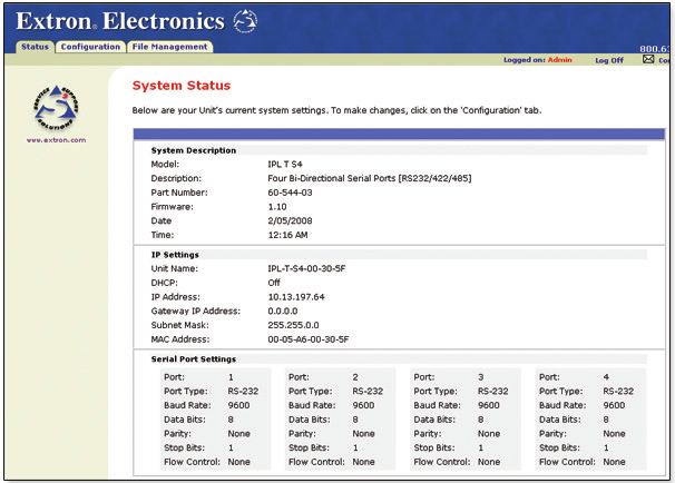
Copyright
© 2016-2022 Extron. All rights reserved. www.extron.com

Trademarks
All trademarks mentioned in this guide are the properties of their respective owners.
The following registered trademarks (®), registered service marks (SM), and trademarks (TM) are the property of RGB Systems, Inc. or Extron (see the
current list of trademarks on the Terms of Use page at www.extron.com):

                                                              Registered Trademarks (®)
 Extron, Cable Cubby, ControlScript, CrossPoint, DTP, eBUS, EDID Manager, EDID Minder, eLink, Flat Field, FlexOS, Glitch Free, Global Configurator,
 Global Scripter, GlobalViewer, Hideaway, HyperLane, IP Intercom, IP Link, Key Minder, LinkLicense, LockIt, MediaLink, MediaPort, NAV,
 NetPA, PlenumVault, PoleVault, PowerCage, PURE3, Quantum, ShareLink, Show Me, SoundField, SpeedMount, SpeedSwitch, StudioStation,
 System INTEGRATOR, TeamWork, TouchLink, V‑Lock, VN‑Matrix, VoiceLift, WallVault, WindoWall, XPA, XTP, XTP Systems, and ZipClip
 Registered Service Mark(SM) : S3 Service Support Solutions
                                                                    Trademarks (™)
 AAP, AFL (Accu‑RATE Frame Lock), ADSP (Advanced Digital Sync Processing), AVEdge, CableCover, CDRS (Class D Ripple Suppression),
 Codec Connect, DDSP (Digital Display Sync Processing), DMI (Dynamic Motion Interpolation), Driver Configurator, DSP Configurator, DSVP (Digital
 Sync Validation Processing), EQIP, Everlast, FastBite, Flex55, FOX, FOXBOX, IP Intercom HelpDesk, MAAP, MicroDigital, Opti‑Torque,
 PendantConnect, ProDSP, QS‑FPC (QuickSwitch Front Panel Controller), Room Agent, Scope‑Trigger, SIS, Simple Instruction Set, Skew‑Free,
 SpeedNav, Triple‑Action Switching, True4K, True8K, Vector™ 4K, WebShare, XTRA, and ZipCaddy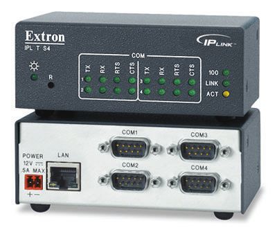
FCC Class A Notice
                 This equipment has been tested and found to comply with the limits for a Class A digital
                 device, pursuant to part 15 of the FCC rules. The Class A limits provide reasonable
                 protection against harmful interference when the equipment is operated in a commercial
                 environment. This equipment generates, uses, and can radiate radio frequency energy and,
                 if not installed and used in accordance with the instruction manual, may cause harmful
                 interference to radio communications. Operation of this equipment in a residential area is
                 likely to cause interference. This interference must be corrected at the expense of the user.

                  ATTENTION:
                     • The Twisted Pair Extension technology works with unshielded twisted pair (UTP)
                       or shielded twisted pair (STP) cables; but to ensure FCC Class A and CE
                       compliance, STP cables and STP Connectors are required.
                     • La technologie extension paires torsadées fonctionne avec les câbles paires
                       torsadées blindées (UTP) ou non blindées (STP). Afin de s’assurer de la
                       compatibilité entre FCC Classe A et CE, les câbles STP et les connecteurs STP
                       sont nécessaires.

                  NOTES:
                     • (This 1st paragraph is for TP ONLY, delete for all others products) This unit was
                       tested with shielded I/O cables on the peripheral devices. Shielded cables must be
                       used to ensure compliance with FCC emissions limits.
                     • (if only this paragraph is used, reformat to single NOTE format.) For more
                       information on safety guidelines, regulatory compliances, EMI/EMF compatibility,
                       accessibility, and related topics, see the Extron Safety and Regulatory
                       Compliance Guide on the Extron website.
                     • Laser products see NOTE on next page

VCCI-A Notice

Battery Notice
                 This product contains a battery. Do not open the unit to replace the battery. If the
                 battery needs replacing, return the entire unit to Extron (for the correct address, see the
                 Extron Warranty section on the last page of this guide).

                  CAUTION: Risk of explosion. Do not replace the battery with an incorrect type. Dispose
                    of used batteries according to the instructions.
                  ATTENTION :       Risque d’explosion. Ne pas remplacer la pile par le mauvais type de
                    pile. Débarrassez-vous des piles usagées selon le mode d’emploi.
Conventions Used in this Guide
     Notifications
                 The following notifications are used in this guide:

                     CAUTION:		        Risk of minor personal injury.
                     ATTENTION :       Risque de blessure mineure.

                     ATTENTION:
                        • Risk of property damage.
                        • Risque de dommages matériels.

                     NOTE: A note draws attention to important information.

     Software Commands
                 Commands are written in the fonts shown here:
                       ^AR Merge Scene,,0p1 scene 1,1 ^B 51 ^W^C.0
                       [01] R 0004 00300 00400 00800 00600 [02] 35 [17] [03]
                       E X! *X1&* X2)* X2#* X2! CE}
                        NOTE: For commands and examples of computer or device responses used in this
                          guide, the character “0” is the number zero and “O” is the capital letter “o.”
                 Computer responses and directory paths that do not have variables are written in the font
                 shown here:
                       Reply from 208.132.180.48: bytes=32 times=2ms TTL=32
                       C:\Program Files\Extron
                 Variables are written in slanted form as shown here:
                       ping xxx.xxx.xxx.xxx —t
                       SOH R Data STX Command ETB ETX
                 Selectable items, such as menu names, menu options, buttons, tabs, and field names are
                 written in the font shown here:
                       From the File menu, select New.
                       Click the OK button.

Specifications Availability
                 Product specifications are available on the Extron website, www.extron.com.

Extron Glossary of Terms
                 A glossary of terms is available at https://www.extron.com/technology/glossary.aspx.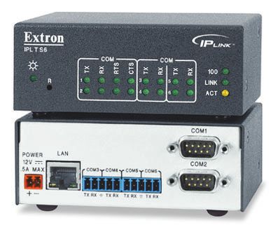
Contents

Introduction................................................ 1                   Communication and Control..................... 25
     About This Guide.................................................. 1            Programmer Guide for Telnet and Web
     About the IPL T S Series Interface........................ 1                     Browsers........................................................... 25
     Features............................................................... 3            Using the Command and Response
                                                                                          Table.......................................................... 25
                                                                                          Symbol Definitions...................................... 26
Installation and Operation.......................... 4
                                                                                     Command and Response Table.......................... 28
     Rear Panel Features and Cabling.......................... 4
                                                                                     Customization.................................................... 41
     Installation Overview............................................. 5
                                                                                          Custom web Pages.................................... 41
           Power........................................................... 5
                                                                                          Server Side Includes (SSI)........................... 41
           Ethernet/LAN................................................ 7
                                                                                          Query String............................................... 42
           Serial Communication................................... 7
                                                                                          Code Examples.......................................... 43
           Identification................................................. 8
                                                                                          URL Encoding............................................ 45
     Operation............................................................. 9
                                                                                     Advanced Serial Port Control.............................. 46
           Front Panel Indicators................................... 9
                                                                                          Serial Pass-through (Redirect Mode) .......... 46
           Resetting the Unit....................................... 10
                                                                                          Direct Port Access (Ports 2001 Through
                                                                                          2006)......................................................... 47
Connection and Configuration.................. 12                                         Serial Bridging............................................ 48
     Connecting the Hardware................................... 12                   Troubleshooting.................................................. 50
          Ethernet Connection................................... 12                       Power Connections.................................... 50
          Serial Connection....................................... 13                     Data Connections....................................... 50
     Setting the Internet Protocol (IP) Address............ 13
          Setting the IP Address Using Global                                    Reference Information.............................. 51
           Configurator.............................................. 14
                                                                                     Mounting the IPL T S Interface........................... 51
          Setting the IP Address Using Embedded
                                                                                        Rack Mounting .......................................... 51
           Web Pages................................................ 15
                                                                                        Furniture or Projector Mounting................... 53
          Setting the IP Address Using the ARP
           Command................................................. 17                  Mounting Options....................................... 54
     Configuration Using Global Configurator............. 18
     Configuration using Embedded Web Pages........ 19
          Connecting Via the Web Server Pages........ 19
          System Status Page................................... 20
          Configuration page..................................... 20
          File Management Page............................... 23
     Configuration Using DataViewer......................... 23

                                                                                                            IPL T S Series • Contents                   vii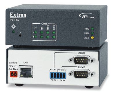
IPL T S Series • Contents viii

Introduction
About This Guide
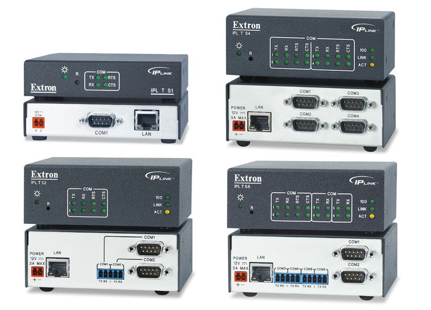
This guide describes the function, installation, configuration, and operation of the
Extron IPL T S Series interface devices which are shown below.
• About the IPL T S Series Interface
• Features
About the IPL T S Series Interface
The Extron IPL T S Series interface devices integrate network connectivity into audio/
video (AV) systems. Installing an IPL T S Series interface into an AV network gives users the
ability to remotely monitor and control projectors, flat-panel displays, switchers, and other
serially-controlled devices.
IPL T S1 control interface
• One bi-drectional RS-232 serial port
• 7.25 MB of available flash memory
• Low-profile form factor
• 1.0 inch H x 4.3 inches W x 3.0 inches D
(2.5 cm x 10.9 cm x 7.6 cm)
IPL T S2 control interface
• Two bi-drectional RS-232, RS-422, or RS-485
serial ports
• 7.25 MB of available flash memory
• 1.7 inches H x 4.3 inches W x 3.0 inches D
(4.3 cm x 10.9 cm x 7.6 cm)
IPL T S4 control interface
• Four bidirectional RS-232, RS-422, or
RS-485 serial ports
• 7.25 MB of available flash memory
• 1.7 inches H x 4.3 inches W x 3.0 inches D
(4.3 cm x 10.9 cm x 7.6 cm)
IPL T S Series • Introduction 1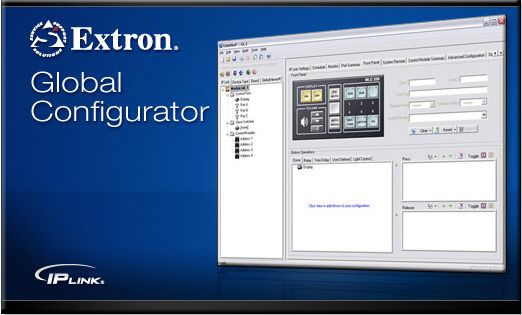
IPL T S6 control interface
•   Six bidirectional RS-232, RS-422, or RS-485
    serial ports
•   7.25 MB of available flash memory
•   1.7 inches H x 4.3 inches W x 3.0 inches D
    (4.3 cm x 10.9 cm x 7.6 cm)

Extron IP Link technology
Each IPL T S Series interface comes with the
Extron IP Link technology including:
•   A built-in web server
•   A set of web pages that can be used to configure the device
•   Flash memory to store the Extron GlobalViewer application and AV equipment device
    drivers
•   Compatibility with the free GlobalViewer application which provides a graphical user
    interface with which to remotely monitor and control your AV network devices
The IPL T S Series interface devices support the following network protocols:
•   DHCP − Dynamic host configuration protocol
•   ICMP − Internet control message protocol
•   SMTP − Simple mail transfer protocol
•   Telnet − a computer/client communications protocol

                       Document
                       Camera
                                                                                                     RS-232

       Codec

                                                                                           CO
                                                                                             M
                                                                                                 1                                              Projector
                                                                                                 2
                                                                                             M
                                                                                           CO

Extron                  UI
                          D#
                               09
                                 30
                                    12

                                    LA
                                         05

                                         N
                                             2

                                                 CO
                                                      M3
                                                           CO
                                                                M4
                                                                      CO
                                                                           M5
                                                                                CO

                                                                                TX
                                                                                     M2

                                                                                      RX

IPL T S6
                                                                           RX
                                                                      TX
                                                                 RX
                         WER                               TX
                       PO                             RX
                         V  X                    TX
                       12 MA

                                                                                                              RS-232
                       .5A

Ethernet Control                                                                                                                               Lighting
                                              TCP/IP
Interface with                                Network
                                                                                                                                               Control
GlobalViewer ®
Software
                   Ethernet

            Remote User
            Control &
            Administrator
            Monitoring                                                                                                 Projector

                                                 Laptop                                              DVD      VCR

Figure 1.       Typical IPL T S Series Application

                                                                                                                                   IPL T S Series • Introduction   2
Features
Support for bidirectional RS-232, RS-422, and RS-485 serial communication —
Allows remote and proactive monitoring and troubleshooting of serially-controlled devices.
NOTE: The IPL T S1 supports RS-232 only.
Serial port pass-through — Two-, four-, and six-port models can be configured
for pass-through mode, enabling each pair of ports on the interfaces to pass through
commands and control a single device.
web-based AV asset management — When used with GlobalViewer software, the IPL
T S interfaces provide a powerful, flexible way to manage, monitor, and control projectors,
flat-panel displays, and other devices using a standard Ethernet network.
Integral, high performance web server — Each IPL T S interface features a built-in
web server with memory available for storing device drivers, GlobalViewer, and development
of your own web pages using “off-the-shelf” web authoring software.
Industry standard Ethernet protocols — All IPL T S models support industry standard
Ethernet communication protocols, including ARP, DHCP, ICMP, UDP/IP, TCP/IP, Telnet,
HTTP, and SMTP, accessed through an RJ-45 auto-sense
10/100 Mbps Ethernet LAN connection.
Simultaneous multi-user support — Each IPL T S interface supports multiple
concurrent users, improving system throughput.
E-mail capabilities to enable support — With e-mail notification, technical support
administrators can receive failure and service messages through an e-mail enabled cell
phone, PDA, pager, or Internet e-mail account.
Multiple levels of access with password protection — User access level authorizes
limited entry to only pre-designated functions, while administrator access level permits full
access to advanced settings.
NOTE: The factory configured passwords for all accounts on this device have been set
to the device serial number. In the event of an absolute system reset, the passwords
convert to the default, which is extron.
Configuration utility — Global Configurator software, a free, easy-to-use
Windows®-based configuration utility, makes product setup simple and intuitive —no
programming knowledge is required.
Extensive library of device drivers — Device drivers allow Extron products to control
various display and source devices, such as projectors, flat-panel displays, and DVD
players. Extron has produced thousands of fully tested and uniformly modeled RS-232 and
IR drivers.
Direct port access — Use existing software programs to control a device that has no
Ethernet support. Any existing Extron product with a serial control port can be interfaced
with a LAN.
Built-in multi-level security — A user can control access to devices attached to the
interface. Two levels of password protection provide appropriate security.
Serial port connectivity — Provides serial ports on 9-pin D and/or 3.5 mm, captive
screw connectors.
Easy configuration and control — Easily control the interface in three ways:
• The Internet Explorer® browser
• A web-based interface
• DataViewer (or a standard Telnet client application)
The IPL T S series requires no centralized processor to operate within a system.
Multiple mounting options — Can be mounted under a desktop or podium, on a
projector mount, or on a rack shelf.
IPL T S Series • Introduction 3Installation and
Operation
• Rear Panel Features and Cabling
• Installation Overview
• Operation
Rear Panel Features and Cabling
All connections, including power, control, input, and output, are on the back panel of the IPL
T S interface. See figures 2, 3, 4, and 5 for details on each model.
¢ ¢ 6
00-05-A6-00-00-02 COM1
00-05-A6-00-00-01
12V
0.5 A
LAN
POWER
COM1 COM2
LAN 12V
COM1 COM2
.5A MAX
TX RX TX RX
1 6 2 34
1 23 4 5 3
Figure 2. IPL T S1 Interface Back Panel Figure 3. IPL T S2 Interface Back Panel
NOTE: The IPL T S2 allows for use of either the 9-pin D connector or the captive screw
connector on COM1 or COM2. The 9-pin D connector COM ports and the captive
screw connector COM ports should not be connected simultaneously.
¢ 6 8 ¢ 6
COM1 COM3 COM1
00-05-A6-00-00-04 00-05-A6-00-00-06
LAN LAN
POWER
POWER COM2
COM2 COM4 12V
12V COM3 COM4 COM5 COM6
.5A MAX
.5A MAX
TX RX TX RX TX RX TX RX
1 23 4 7 9 1 23 4 5 7
Figure 4. IPL T S4 Interface Back Panel Figure 5. IPL T S6 Interface Back Panel
IPL T S Series • Installation and Operation 4Installation Overview
To install and set up an IPL T S interface, follow these steps:
1. Turn all of the equipment off. Make sure that the video sources (DSS, cable boxes, or
other devices), the IPL T S unit, the output devices (monitors, VCRs, projectors, and so
on) and the serial controller are all turned off and disconnected from the power source.
2. Mount the IPL T S interface (see Rear Panel Features and Cabling on the previous
page).
3. Attach the cables (see Connecting the Hardware on page 12).
4. Connect power cords and turn on the devices in the following order: output devices
(projectors, monitors, speakers), IPL T S interface, serial controller or computer (PC),
then input devices (DSS, cable boxes, and so on).
5. Configure the IPL T S interface through DataViewer or Telnet, then access the unit using
an Internet browser.
Power
1 Power connection — Plug the external 12 VDC power supply for the unit into this
connector. The power supply is provided with the unit.
ATTENTION:
• When you are connecting the power supply, voltage polarity is extremely
important. Applying power with incorrect voltage polarity could damage the
power supply and the interface. Identify the power cord negative lead by the
ridges on the side of the cord.
• Lorsque vous connectez la source d’alimentation, la polarité de la tension
est extrêmement importante. Une alimentation avec une polarité de tension
incorrecte peut endommager la source d’alimentation ainsi que l’interface. Il
est essentiel d’identifier une connexion négative du cordon d’alimentation au
niveau des stries sur les parties latérales du cordon.
• If not provided with a power supply, this product is intended to be supplied
by a UL Listed power source marked Class 2 or LPS and rated output 12
VDC, minimum 0.5 A.
• Si le produit n’est pas fourni avec une source d’alimentation, il doit être
alimenté par une source d’alimentation certifiée UL de classe 2 ou LPS, avec
une tension nominale 12 Vcc, 0,5 A minimum, et supporter une température
ambiante de 50°C.
• Always use a power supply supplied or specified by Extron. Use of an
unauthorized power supply voids all regulatory compliance certification and
may cause damage to the supply and the unit.
• Utilisez toujours une source d’alimentation fournie ou recommandée par
Extron. L’utilisation d’une source d’alimentation non autorisée annule toute
certification de conformité réglementaire, et peut endommager la source
d’alimentation et l’unité.
• Unless otherwise stated, the AC/DC adapters are not suitable for use in air
handling spaces or in wall cavities.
• Sauf mention contraire, les adaptateurs CA/CC ne conviennent pas à une
utilisation dans les espaces d’aération ou dans les cavités murales.
IPL T S Series • Installation and Operation 5ATTENTION:
• The installation must always be in accordance with the applicable
provisions of National Electrical Code ANSI/NFPA 70, article 725 and the
Canadian Electrical Code part 1, section 16. The power supply shall not be
permanently fixed to building structure or similar structure.
• L’installation doit toujours être conforme aux dispositions applicables du
Code américain de l’électricité (National Electrical Code) ANSI/NFPA 70,
article 725, et du Code canadien de l’électricité. La source d’alimentation
ne devra pas être fixée de façon permanente à la structure de bâtiment ou à
d’autres structures similaires.
Smooth Ridges
A A
SECTION A–A
3/16"
Power Supply (5 mm) Max.
Output Cord
Orange Captive
Screw Connector
Ground
+12 VDC
Power Supply
Output Cord
External
Power Supply
(12 VDC, 1 A )
AC Power Cord
Figure 6. Power Connector Wiring
ATTENTION:
• Do not tin the stripped power supply leads before installing the captive screw
connector. Tinned wires are not as secure in the captive screw connectors
and could pull out.
• Ne pas étamer le câble d’alimentation dénudé avant d’avoir installé le bornier
à vis. Les câbles étamés ne sont pas aussi bien fixés dans les borniers à vis
connecteurs et pourraient s’arracher.
• The two power cord wires must be kept separate while the power supply is
plugged in. Remove power before continuing.
• Les deux cordons d’alimentation doivent être maintenus à l’écart tant
que la source d’alimentation est branchée. Avant de continuer, coupez
l’alimentation.
To verify the polarity before connection, plug in the power supply with no load and
check the output with a voltmeter.
IPL T S Series • Installation and Operation 6Ethernet/LAN
2 LAN activity LED — A blinking yellow LED indicates LAN activity.
3 LAN connector — An RJ-45 connector for a network connection. Use an Ethernet
straight-through cable to connect to a switch, hub, or router, or an Ethernet crossover
cable to connect directly to a PC.
00-05-A6-00-00-02 COM1
Straight-through Cable
(for connection to a switch, hub, or router)
POWER
LAN End 1 End 2
COM2
12V
.5A MAX
COM1 COM2 Pin Wire Color Pin Wire Color
1 white-orange 1 white-orange
TX RX TX RX
2 orange 2 orange
3 white-green 3 white-green
4 blue 4 blue
2 34 5 white-blue 5 white-blue
6 green 6 green
7 white-brown 7 white-brown
8 brown 8 brown
Pins:
12345678
Crossover Cable
(for direct connection to a PC)
End 1 End 2
Pin Wire Color Pin Wire Color
1 white-orange 1 white-green
2 orange 2 green
3 white-green 3 white-orange
Side View 4 blue 4 blue
Insert 5 white-blue 5 white-blue
Twisted 6 green 6 orange
Pair Wires 7 white-brown 7 white-brown
RJ-45 Connector 8 brown 8 brown
Figure 7. RJ-45 Connector Wiring
4 Link LED — A lit green LED indicates a good LAN connection.
Serial Communication
5 Captive screw connector — Plug a 3.5 mm, 5-pole captive screw connector into
this socket for serial ports 1 and 2 (IPL T S2) or serial ports 3 through 6 (IPL T S6)
connections. Pacing and handshaking are not supported via the captive screw
connectors.
NOTE: The two IPL T S2 captive screw connectors are in parallel with the two
9-pin D connectors. For each serial port on the S2 use either the captive screw
connector or the 9-pin D connector, but not both.
6 COM1 — 9-pin D connector for serial port 1
7 COM2 — 9-pin D connector for serial port 2
8 COM3 — 9-pin D connector for serial port 3 (S4 only)
9 COM4 — 9-pin D connector for serial port 4 (S4 only)
IPL T S Series interface devices can be used to control display devices, switchers, and other
AV equipment via an RS-232/RS-422/RS-485 connection.
IPL T S Series • Installation and Operation 7Factory default protocol for the control interface is:
• RS-232 • 8 data bits • pacing = 0 ms
• 9600 baud • 1 stop bit • handshaking = off
• no parity
Communication to an attached device can be done through the IPL T S Series device
default web pages or by using the Extron Simple Instruction Set (SIS) commands.
The rear panel 9-pin D connector COM ports have the following pin assignments:
Pin Function RS-232 RS-422 RS-485
2 Receive Data/Receive Data - RX RX- Data -
3 Transmit Data/ Transmit Data - TX TX- (pins 2 + 3 tied)
5 Signal Ground GND GND GND
7 Request to Sent/Transmit Data + RTS TX+ Data +
8 Clear to Send/Receive Data + CTS RX+ (pins 7 + 8 tied)
NOTE: The IPL T S1 uses RS-232 only.
• When using RS-485 with the connections indicated 5 1
above:
Data+ can connect to either pin 7 or pin 8.
9 6
Data- can connect to either pin 2 or pin 3.
9-Pin D Connector
• For RS-232 communication, pins 7 and 8 (RTS and CTS) Pin Locations, Female
are optional.
IPL T S2 IPL T S6
Connectors Connectors
COM1 COM2 COM3 COM4 COM5 COM6
7/8”
TX RX TX RX TX RX TX RX TX RX TX RX (22 mm)
Heat
Shrink 1/8”
(3 mm)
3/16”
(5 mm) Max.
5-pole Captive Screw
Connector
Transmit
Receive
Transmit
Receive
Transmit
Receive
Transmit
Receive
Transmit
Receive
Transmit
Receive
Ground
Ground
Ground
Figure 8. 5-pin Captive Screw Assignments
COM ports 1 and 2 of the IPL T S2 can be wired in a similar way as the IPL T S6, as shown
in figure 8. Both can be wired using a 3.5 mm, 5-pole or 3-pole captive screw connector.
NOTE: The IPL T S2 allows for use of either the 9-pin D connector on COM1 or COM2.
The 9-pin D connector COM ports and the captive screw connector COM ports
cannot be connected simultaneously.
Identification
¢ UID # — The unique user ID number (MAC address) of the unit (for example,
00-05-A6-00-00-01).
IPL T S Series • Installation and Operation 8Operation
Connect power cords and turn on the output display devices (projectors, monitors, VCRs),
control devices (switchers, scalers, distribution amplifiers), interface, and input devices (PC,
laptop, network equipment).
Check indicator LEDs on the PC or laptop, the interface, the network hub or router, and so
on, to ensure that all the devices are plugged in and communicating. The IPL T S interface is
now ready to be configured (see Connection and Configuration starting on page 12).
If connection or communication problems occur, see Troubleshooting on page 50. If
the troubleshooting tips do not help, check with your local network administrator, or call the
Extron S3 Sales & Technical Support Hotline.
Front Panel Indicators
The front panels of the IPL T S interfaces have several indicator LEDs that show the current
status of communications to and from the unit. A reset button (B) is also available from the
front panel, in a small recess next to the Power LED.
IPL T S2
COM
COM
9
CTS
RTS
100
RX
TX
R TX RTS
RX CTS
R 1
2
LINK
ACT
8
IPL T S1 7
123 4 6 5 12 34 56
Figure 9. IPL T S1 Front Panel Figure 10. IPL T S2 Front Panel
IPL T S4 IPL T S6
COM COM COM
9 9
CTS
CTS
RTS
RTS
CTS
RTS
100
RX
100
RX
RX
TX
TX
TX
RX
RX
TX
TX
R 1
2
3
4
LINK
ACT
8 R 1 3 5 LINK
8
7 2 4 6 ACT
7
1 2 3 4 5 63 4 5 6 1 2 3 45 6 3 4 5 6
Figure 11. IPL T S4 Front Panel Figure 12. IPL T S6 Front Panel
1 Power LED — A green LED lights to indicate that the interface is receiving power.
2 Reset button (recessed) — A multi-function reset button (see Resetting the Unit
on the next page).
3 TX LEDs — A green LED indicates data is being transmitted from the corresponding
serial port (see figures 9, 10, 11, and 12).
4 RX LEDs — A green LED indicates data is being received by the corresponding serial
port.
5 RTS LEDs — A green LED indicates that the corresponding serial port is ready to send
data.
6 CTS LEDs — A green LED indicates that the device controlled by the corresponding
serial port is ready to accept data.
7 ACT (Activity) LED — A yellow LED indicates that data is being sent or received.
8 LINK LED — A green LED indicates that the unit is connected to an active network.
9 100 LED — A green LED indicates that the connection speed is 100 Mbps. If the LED
is not lit, the connection speed is 10 Mbps.
IPL T S Series • Installation and Operation 9Resetting the Unit
There are five reset modes available by pressing the Reset button on the front panel (see
figures 9 through 12, 2 on the previous page). The Reset button is recessed, so use
a pointed stylus, ballpoint pen, or Extron Tweeker to access it. See the Reset Mode
Comparison Summary table on the next page for a description of the modes.
ATTENTION:
• Review the reset modes carefully. Using the wrong reset mode may result
in unintended loss of flash memory programming, port reassignment, or a
controller reboot.
• Analysez minutieusement les différents modes de réinitialisation. Appliquer
le mauvais mode de réinitialisation peut causer une perte inattendue de la
programmation de la mémoire flash, une reconfiguration des ports ou une
réinitialisation du processeur.
• The reset modes listed below (with the exception of Mode 2) close all open IP
and Telnet connections and close all sockets.
• Les modes de réinitialisation répertoriés ci-dessous (à l’exception du Mode
2) ferment toutes les connexions IP et Telnet ouvertes ainsi que les prises de
courant.
• If the Reset button is continuosly held down, every three seconds the LED
pulses (blinks) and puts the unit in a different mode. The Mode 5 LED blinks
three times, the third blink indicating that it is the last mode. The following modes
are separate functions, not a continuation from Mode 1 to Mode 5.
IPL T S Series • Installation and Operation 10Reset Mode Comparison Summary
Mode Activation Results Purpose
1 Hold down the recessed Reset The unit reverts to the factory default firmware. Use mode 1 to revert to the
button while applying power to factory default firmware version if
Event scripting does not start if the unit is powered
the IPL T S unit. incompatibility issues arise with
on in this mode. All user files and settings (drivers,
user-loaded firmware.
NOTE: After a mode 1 reset adjustments, IP settings, and so forth) are maintained.
is performed, update the
unit firmware to the latest
NOTE: If you do not want to update firmware,
or you performed a mode 1 reset by mistake,
version. Do not operate
cycle power to the unit to return to the firmware
the unit firmware version
version that was running prior to the mode 1
that results from the mode
1 reset. If you want to reset. Use the 0Q SIS command to confirm that
use the factory default the factory default firmware is no longer running
firmware, you must upload (look for asterisks following the version number.)
that version again.
2 Press and release the Reset The connected COM port becomes a console port to Mode 2 enables the SIS console
button. Within 2 seconds type send SIS commands. Scripting remains on. port.
+++ on the keyboard.
NOTE: If the three + signs
(+++) are not entered in
the 2-second time frame,
the COM port becomes a
control port only.
3 Hold down the Reset button for Mode 3 turns events on or off. Mode 3 is useful for
about 3 sec. until the Reset LED troubleshooting.
During resetting, the Reset LED blinks two times if
blinks once.
events are starting, three times if events are stopping.
Then press Reset momentarily
(Connection and
Configuration
This topics in this section are:
• Connecting the Hardware
• Setting the Internet Protocol (IP) Address
• Configuration Using Global Configurator
• Configuration Using Embedded Web Pages
• Configuration Using DataViewer
Connecting the Hardware
To connect the IPL T S interface, connect the input and output devices to the unit. Use
figure 13 as a guide.
Extron
IPL T S2
Ethernet Control Serial Cables
Interface to Controlled Devices
(switcher, projector, etc.)
1
M
CO
2
M
CO
M2
2 CO
05
12 CO
M1
30
# 09
UID RX
N TX
LA RX
TX
WER
PO
V
12 MAX
.5A
TCP/IP
Network
Crossover
Ethernet or Cable
Laptop
PC
Figure 13. IPL T S Interface Connections
Ethernet Connection
Ethernet connection is used on an ongoing basis to connect the IPL T S unit to a LAN and
to control the switching and display devices attached to the unit. To connect the unit to a
LAN, do the following:
1. Plug one end of a CAT 5, straight-through Ethernet cable into the rear panel Ethernet
connector on the IPL T S unit. See figures 2-9 in chapter 2 for RJ-45 connector wiring
information.
2. Plug the other end of the Ethernet cable into a network switch or hub connected to an
Ethernet LAN or to the Internet.
3. From your PC, launch a web browser and type in the IP address previously set up
on the IPL T S. If this has not been set up, see Setting the Internet Protocol (IP)
Address on page 13. This displays the System Status web page.
IPL T S Series • Connection and Configuration 12Serial Connection
The IPL T S interface can be connected to any AV device that has a serial control port.
1. Connect one end of a serial cable to the rear panel COM port connector of the IPL T S
unit. As an alternative, use a 3.5 mm, 5-pole captive screw connector where available.
NOTE: This captive screw connector must be wired appropriately (see figure 8 on
page 8 for pin assignments).
Lighting
Control
RS-232
Extron
Extron MAV 62
IPL T S4 Matrix Switcher
CO
M
3
Ethernet Control
CO
M
1
CO
M
2
Interface
2 2
05 M
12 CO
30
09
D#
UI
N
LA
RS-232
R
WE p
PO pto
V X La
12 MA
.5A
D
DV
R
VC
LAY
DISP ER
POW
206
MLC roller
Cont
ME aLink
VOLU Medi
TCP/IP MAX/
MIN
Network
RS-232 Ex
tron
Extron
Ethernet MediaLink or
Other Controller
Remote User
Control and
Administrator
Monitoring
Projector
Laptop DVD VCR
Figure 14. Typical IPL T S Interface Operating Configuration
2. Connect the other end of the serial cable to the display or switching device to be
controlled through the IPL T S.
Setting the Internet Protocol (IP) Address
The IPL T S Series units have a factory default IP address of 192.168.254.254. This IP
address must be changed to an address that will operate on your local network.
There are three ways to change the IP address setting:
• Add Device > Auto Config IP option in Global Configurator
• IPL T S embedded web pages
• Address Resolution Protocol (ARP) command
Before you begin:
1. Obtain a valid IP address for your IPL T S Series device from your AV system network
administrator.
2. Write down the unit MAC address (a 12-digit number) found on a label on the rear panel
of the unit (for example, 00-05-A6-01-0A-74).
3. If the unit is not at the factory default IP address (192.168.254.254), perform a Mode 4
reset:
a. Hold down the Reset button until the Power LED blinks twice (6 seconds), then
release.
b. Press and release the Reset button again within 1 second.
IPL T S Series • Connection and Configuration 13c. The Power LED blinks quickly four times, confirming the Mode 4 reset, which
returns the unit to its factory default IP address.
IPL T S4
COM
CTS
CTS
RTS
RTS
100
RX
RX
TX
TX
R 1 3 LINK
2 4 ACT
1 2
Figure 15. IPL T S Front Panel
1 Power LED — A green LED lights to indicate that the interface is receiving power.
Blinks four times to confirm a Mode 4 reset.
2 Reset button — The Reset button is recessed. Use an Extron Tweeker, stylus or
similar tool to activate.
Setting the IP Address Using Global Configurator
The preferred method for setting a unit IP address is to use the Extron Global Configurator
(GC) application.
If you have Global Configurator installed on a local PC, and have a GC project file open,
proceed with the steps below. If you do not have Global Configurator installed, it is available
as a free download from www.extron.com. The GC help file leads you through the process
of creating a new GC project file, and provides an illustrated version of the procedure below.
The IPL T S unit must be:
• physically connected to the network
• at its factory default IP address
To set an IP address with a GC project file open:
1. From the Edit menu, select Add Device.
The Add Device dialog box opens (see figure 16 on page 15).
2. Select the appropriate device type (for example, IPL T S4) in the IP Link Device
drop‑down list.
3. Enter the new IP address (for example, 10.14.195.40) in the Name/IP Address field.
4. Enter a unique device name in the Display Name field.
5. Click the Advanced >>> button.
The Advanced options of the Add Device dialog are displayed, and the Advanced >>>
button name changes to BasicFigure 16. Setting the IP Address in Global Configurator
Setting the IP Address Using Embedded Web Pages
Each IPL T S unit contains an on-board web server with interactive pages that can be used
to configure the device.
NOTE: The IPL T S unit must be at its factory default IP address.
To set an IP address via embedded web pages:
1. Connect an Ethernet crossover cable between the IPL T S and a local PC.
2. On the PC, locate the TCP/IP Properties dialog box.
In Windows®, the TCP/IP Properties dialog box is found at:
Start > My Network Places > right-click on Properties > Local Area Connection
> right-click on Properties > Internet Protocol (TCP/IP) > Properties.
3. Record the current IP address, subnet mask, default gateway and DHCP settings. You
will need this information later to return the PC to its original TCP/IP settings.
IP Address:
. . .
Subnet Mask:
. . .
4. Enter the following:
IP address: 192.168.254.253
Subnet mask: 255.255.0.0
Default gateway:
5. Click OK.
IPL T S Series • Connection and Configuration 15Figure 17. Internet Protocol (TCP/IP) Properties Dialog Box
6. Open a web browser on the local PC.
7. Enter 192.168.254.254 in the browser Address field and press the Enter key.
The IPL T S unit embedded web page is displayed.
8. Click the Configuration tab.
9. Change the IP Address and Subnet Mask fields to the desired IP address and subnet
mask.
10. Click the Submit button.
The new IP address and subnet mask are assigned to the device, and the web browser
connection is immediately lost.
The device, with its new IP address and subnet mask is now ready to be connected to
your AV network.
Figure 18. Web Server System Settings Screen
IPL T S Series • Connection and Configuration 16To return the local PC to its original TCP/IP settings:
1. Close the web browser.
2. Disconnect the Ethernet crossover cable from the PC and the device.
3. Return to the TCP/IP Properties dialog box on the PC.
4. Return the IP address, Subnet mask, Default gateway, and DHCP fields to their original
settings.
5. Reboot the PC.
Setting the IP Address Using the ARP Command
An IPL T S unit IP address can be set using the DOS Address Resolution Protocol (ARP)
command.
The IPL T S unit must be:
• Physically connected to the network
• At the factory default IP address
To set an IP address using the ARP command:
1. Open a command prompt window on a local PC. On Windows XP, a command prompt
window can be found at:
Start > All Programs > Accessories > Command Prompt
2. At the command prompt type:
arp - s
example: C:\>arp -s 10.13.197.64 00-05-A6-00-30-5F
The example command assigns IP address 10.13.197.64 to the device that has a MAC
address of 00-05-A6-00-30-5F.
Figure 19. Executing the ARP Command
3. To confirm the new IP address is active, perform a ping command to the new IP
address.
example: C:\>ping 10.13.197.64
If the IP address setting was successful, the device replies 3 or more times:
Reply from : bytes=32 timeConfiguration Using Global Configurator
Global Configurator (GC) is a simple-to-use, yet comprehensive software application that allows
non-programmers to configure a wide range of Extron IP Link-enabled products. GC provides
an integrated environment for defining AV control and monitoring system functionality from an
easy-to-use graphical user interface. It simple enough to be used for configuring a single room
controller, yet powerful enough to facilitate building a web-based asset management and remote
monitoring system for hundreds of AV devices in multiple locations.
Serial ports on the IPL T S Series devices can be configured using GC.
Global Configurator is available for free from www.extron.com.
To download Global Configurator:
1. Open and Internet browser and advance to www.extron.com.
2. Click the Download tab.
3. Click the Global Configurator icon.
4. Click the Download Now button.
5. Complete the Personal Information form.
6. Scroll down the page and review any related Technical Bulletins.
7. Click the Download GCSW3XX.exe button.
8. Follow the remaining system prompts.
Figure 20. Global Configurator
Once installed on your local PC, Global Configurator can be used to configure your IPL T S
Series device and the AV devices that are attached to the S Series serial control ports.
See the Global Configurator help file for instructions on how to:
• Download device drivers
• Start Global Configurator
• Create a GC project file
• Add and configure IPL T S Series and AV devices
IPL T S Series • Connection and Configuration 18Configuration Using Embedded Web Pages
Each IPL T S unit contains an on-board web server with interactive pages that can be used
to configure the device. web server pages are described in detail on the following pages.
Connecting Via the Web Server Pages
To connect to an IPL T S Series device via its web server pages:
1. Open a web browser on a local PC.
2. Enter the device IP address in the browser Address field and press the Enter key. If the
device is password-protected, you are prompted for a password.
NOTE: The factory configured passwords for all accounts on this device have been
set to the device serial number. In the event of an absolute system reset, the
passwords convert to the default, which is extron.
Figure 21. Web Server Password Dialog Box
3. Enter the appropriate administrator or user password.
4. Click OK. The System Status page opens.
Figure 22. Web Server System Status Screen
IPL T S Series • Connection and Configuration 19System Status Page
The System Status page is a read-only page that provides the following status information:
• System Description — Model, Description, Part Number, Firmware, Date, and Time
• IP Settings — Unit Name, DHCP setting, IP Address, Gateway IP Address, Subnet
Mask, and MAC Address
• Serial Port Settings — For each port: Port number, Port Type, Baud Rate, Data Bits,
Parity, Stop Bits, and Flow Control
Figure 23. System Status Screen
Configuration page
The Configuration page has five sub-pages, which are described below.
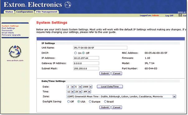
System Settings
The System Settings page grants access to view and change:
• IP Settings
• Date/Time Settings
Figure 24. System Settings Screen
IPL T S Series • Connection and Configuration 20Port Settings
The Port Settings page grants access to view or change the Serial Port Settings:
• Serial port number — use a radio button to select the desired port
• Port type — RS-232 (default), RS-422, 4S-485
• Baud rate — 300, 600, 1200, 1800, 2400, 3600, 4800, 7200, 9600 (default), 14400,
19200, 28800, 38400, 57600, 115200
• Parity — 7, 8 (default)
• Stop bits — 1 (default), 2
• Flow control — None (default), Hardware, Software
• Serial Bridging — On, Off (default)
• Remote IP Address — view the remote IP address
• Remote TCP Port — view the remote TCP port
Figure 25. Port Settings Screen
Passwords
NOTE: The factory configured passwords for all accounts on this device have been set
to the device serial number. In the event of an absolute system reset, the passwords
convert to the default, which is extron.
The Passwords page fields include:
• Administrator Password — provides complete configuration control
• User Password — allows view of configuration only
Figure 26. Passwords Screen
To clear a password, enter a single space, repeat the entry in the re-enter password field,
then click the Submit button.
If no administrator password is present, the user password is not saved.
IPL T S Series • Connection and Configuration 21Email Alerts
Initial e-mail alerts must be created using Global Configurator software. The embedded web
pages only allow you to edit existing e-mail alert settings.
The Email Alerts page allows you to:
• Edit your network mail server connection information
• Edit e-mail addresses of those you wish to receive e-mail alerts
• Select the desired e-mail delivery files
Fields include:
• Mail IP Address — the network mail server IP address
• Domain Name — the network mail server domain name
• SMTP Authentication Required — SMTP authentication is required to access the
mail server
• User Name — user name to access the network mail server
• Password — password to access the network mail server
NOTE: The factory configured passwords for all accounts on this device have been
set to the device serial number. In the event of an absolute system reset, the
passwords convert to the default, which is extron.
• Email Address — e-mail addresses of those to receive e-mail alerts
• File Name — file name of the desired e-mail message
Figure 27. Email Alerts Screen
Firmware Upgrade
The Firmware Upgrade page reports the current firmware level, and provides the capability
to browse to and upload a new firmware file.
Figure 28. Firmware Upgrade Screen
IPL T S Series • Connection and Configuration 22File Management Page
The File Management page allows you to create directories as well as upload, use, and
delete custom web pages.
Use the Add Dir, Browse, Upload Files and Delete buttons to upload and manage
your custom web pages.
Figure 29. File Management Screen
Configuration Using DataViewer
DataViewer is an enhanced terminal emulation program that facilitates analysis of RS-
232 and TCP/IP communication with Extron devices. The software allows users to send
commands to a device and view the device responses in ASCII or hexadecimal format.
Command and response logs can be saved in text or HTML format.
The data display can be configured in several ways for improved analysis of data
communication. Text colors and fonts are user-definable making it easy to differentiate
between commands and responses. Four different screen view options are available for
viewing commands and responses in the most effective configurations and formats.
With the DataViewer Control Toolbar and Shift Toolbar, you can customize up to 20 shortcut
keys. Shortcut keys can be used to automate repetitive communications tasks. DataViewer
is ideal for troubleshooting device protocols and determining device timing.
DataViewer is available free from www.extron.com.
To download DataViewer:
1. Open an Internet browser and go to www.extron.com.
2. Click the Download tab.
3. Click the Control Software icon.
4. Scroll to the description of DataViewer.
5. Click the Download link in the far right column.
6. Complete the Personal Information form.
7. Click the Download DVSW1x2x0x4.exe button.
8. Follow the remaining system prompts.
IPL T S Series • Connection and Configuration 23Figure 30. DataViewer Main Window
To run DataViewer:
1. Double-click the DataViewer icon that was placed on the PC desktop
during the download procedure.
2. The Communications Setup dialog box opens (see figure 31).
3. Click the TCP/IP tab.
4. Enter the device IP address in the Hostname/IP Address field.
5. Click OK.
Figure 31. Communication Setup Dialog Box
The DataViewer application opens (see figure 30).
See the DataViewer help file for information on sending commands to the
IPL T S Series device, and viewing the responses in the DataViewer user interface.
IPL T S Series • Connection and Configuration 24Communication and
Control
The topics covered in this section are:
• Programmer Guide for Telnet and Web Browsers
• Customization
• Advanced Serial Port Control
• Troubleshooting
Programmer Guide for Telnet and Web Browsers
Using the Command and Response Table
The following are either Telnet (port 23) or web browser (port 80) commands. There are
some minor differences when you are implementing these commands via Telnet or via URL
encoding using a web browser. All commands listed below work using either connection
method; but, due to some limitations of the web browser, the encapsulation characters are
modified to make sure that the web browser properly handles them. All examples in the
command/response table on
page 4-6 show the proper implementation in a Telnet or web browser session.
NOTE: For web browsers: all non-alphanumeric characters must be represented as their
hex equivalent, for example, %xx where xx equals the two character representation of
the hex byte that needs to be sent (for example, a comma would be represented as
%2C).
Telnet Web Browser
Escape (Hex 1B) W (must not be encoded)
Carriage return (Hex 0D) Pipe character (|) (must not be encoded)
When these commands are used through a web browser, the URL reference is used below
to shorten the examples. This would in practice be the full URL of the control interface and
web page reference including all path information, for example, http://192.168.100.10/
myform.htm.
To send any of the commands using a web browser, you need to prefix them with the full
URL followed by ?cmd= (see URL Encoding on page 45).
NOTE: With Telnet you can use either the Escape commands with the carriage return or
the W commands with the pipe (|) character. With the web browser you are required
to use the W commands and the pipe character.
IPL T S Series • Communication and Control 25The Command and Response Table for Simple Instruction Set (SIS) commands starting
on page 28 lists the commands that the IPL T S interface recognizes as valid, the
responses that are returned to the host, a description of the command function or the
results of executing the command, and an example of each command in ASCII (Telnet) and
URL Encoded (web).
NOTE: Upper- and lowercase text can be used interchangeably except where noted.
Symbol definitions are shown below. An ASCII to HEX conversion table is also provided in
table 1.
ASCII to HEX Conversion Table
•
Table 1. ASCII-to-HEX Conversion Table
Symbol Definitions
Common Symbol Definitions
] = CR/LF (carriage return/line feed)
] = Carriage return with line feed (hex 0D 0A)
} or ¦ = Carriage return or pipe symbol (no line feed, hex 0D)
} = Carriage return with no line feed (no line feed, hex 0D) (for URL-encoded commands, use the pipe
character, | , instead)
E = Escape key, or hex 1B (use W instead of E for web browsers, or at any time)
| = Pipe (vertical bar) character (URL equivalent to carriage return)
• = Space
* = Asterisk character (which is a command character, not a variable)
NOTE: For commands and examples of computer or device responses used in this guide, the
character 0 is the number zero and O is the capital letter o.
IPL T S Series • Communication and Control 26Error responses
When the IPL T S interface receives a valid command, it executes the command and sends
a response to the host device. If the unit is unable to execute the command because the
command contains invalid parameters, it returns an error response to the host.
E12 — Invalid port number
E13 — Invalid parameter
E14 — Not valid for this configuration
E17 — System timed out
E22 — Busy
E24 — Privilege violation
E25 — Device not present
E26 — Maximum number of connections exceeded
E27 — Invalid event number
E28 — Bad filename/file not found
E31 — Attempt to break port pass-through when not set. (A user or software attempted to
disable the port redirect feature when it wasn’t already set or active.)
References to errors (at command descriptions on the following pages)
13
= Commands that give an E13 (invalid parameter) error
24
= Commands that give an E24 (privilege violation) error if not administrator level
27
= Commands that may give an E27 (invalid event number) error
28
= Commands that may give an E28 (file not found) error
ASCII to decimal conversion table
ASCII to Decimal Conversion Table
To find the decimal equivalent of the ASCII character, add
the row heading and column heading numbers together.
0 1 2 3 4 5 6 7 8 9
10 LF CR
20 Esc
30 space ! “ # $ % & ’
40 ( ) * + , - . / 0 1
50 2 3 4 5 6 7 8 9 : ;
60 < = > ? @ A B C D E
70 F G H I J K L M N O
80 P Q R S T U V W X Y
90 Z [ \ ] ^ _ ‘ a b c
LF = line feed
100 d e f g h i j k l m
CR = carriage return (})
110 n o p q r s t u v w Esc = escape
120 x y z { | } ~ Del Del = delete
IPL T S Series • Communication and Control 27Command and Response Table
Command ASCII (Telnet) URL Encoded (Web) Response Additional Description
(Host to Unit) Host to Unit) (Unit to Host)
Bidirectional Serial Data Port
Send data string E X!*X1&*X2)*X2!RS}X@ W X! %2A X1& %2A X2) %2AX2! response from command] X1& = The response includes leading zeros.
RS|X@ X2! = The ASCII decimal delimiter # value can be
from 0 to 00255, default = the byte count.
Examples: A 3-byte length = 3L. A delimiter
of ASCII 0A = 10D.
NOTES:
• * X1& * X2) * X2! is optional. X1& is optional only if X2) is also missing. If these three variables are not specified, the default values are used. For this command, X1& and X2) must both a) equal
zero or b) be nonzero.
• For web encoding for X@, convert non-alphanumeric characters to hex numbers. A space (hex = 20) is encoded as %20. A plus sign (hex = 2B) is encoded as %2B.
Example: E05*4*7*3L RS } W05%2A4%2A7%2A3L RS| response from command ]
• The data string (X@) in this RS command is limited to 200 bytes.
KEY:
X! = Specific port number (01 – 99) 1 = rear host (Host Control RS-232 port) 4 = display port (Projector RS-232/IR) 7 = IR/Serial port C
2 = front panel Config port 5 = IR/Serial port A
3 = secondary switcher (MLS port) 6 = IR/Serial port B
X@ = Command data section X@ is the command string for sending data to an AV product (for example, a switcher or projector) attached to an IPL T S unit
(see Customization on page 41 for remote processing examples and see URL Encoding on page 45 for command restrictions
X1& = Time in tens of milliseconds to wait for characters coming into a serial port before terminating (default = 1 = 10 ms, max. = 32767)
X2) = Time in tens of milliseconds to wait between characters coming into a serial port before terminating (default = 2 = 20 ms, max. = 32767)
X2!
= Parameter to set either Length of message to receive or Delimiter value. If length delimited, use xxL, where xx is the length of the incoming message in bytes. If character delimited, use
xxD, where xx is the decimal ASCII value of the delimiting character.
IPL T S Series • Communication and Control 28Command ASCII (Telnet) URL Encoded (Web) Response Additional Description
(Host to Unit) Host to Unit) (Unit to Host)
Bidirectional Serial Data Port (continued)
Configure parameters24 E X!* X2%, X2^, X2&, WX! %2A X2% %2CX2^ %2CX2& Cpn X!•CcpX2%, X2^, X2&, Set baud rate (X2%), parity (X2^), data bits (X2&), and
X2*CP} %2CX2*CP | X2* ] stop bits (X2*) for port X!.
Example: E4*9600,N,8,1CP} W4%2A9600%2CN%2C8%2C Cpn4•Ccp9600,N,8,1] Set the projector control port for 9600 baud,
1CP| no parity, 8 data bits, and 1 stop bit.
View parameters E X!CP} W X!CP| X2%, X2^, X2&, X2( ]
Configure mode24 E X!*X2(CY} WX!%2AX2(CY| CpnX!•CtyX2)]
View mode E X!CY} WX!CY| X2(]
Configure flow control E X!*X3),X3!CF} WX!%2AlX3)%2CX3!CF| CpnX!•CflX3),X3!]
View flow control E X!CF} WX!CF| X3), X3!]
Configure receive E X!*X1&*X2) , X2# *X2!CE} WX!%2AX1&%2AX2)%2AX2# CpnX!•CceX1&*X2) , X2# , X2! ] Set the time to wait (X1& and X2)) and priority
timeout24 %2AX2!CE| status (X2#) for port X!.
View receive timeout E X!CE} WX!CE| X1& , X2) , X2# , X2! ]
KEY:
X!
= Specific port number (01 – 99) 1 = rear host (Host Control RS-232 port) 4 = display port (Projector RS-232/IR) 7 = IR/Serial port C
2 = front panel Config port 5 = IR/Serial port A
3 = secondary switcher (MLS port) 6 = IR/Serial port B
X1& = Time in tens of milliseconds to wait for characters coming into a serial port before terminating (default = 1 = 10 ms, max. = 32767)
X2) = Time in tens of milliseconds to wait between characters coming into a serial port before terminating (default = 2 = 20 ms, max. = 32767)
X2! = Parameter to set either Length of message to receive or Delimiter value. If length delimited, use xxL, where xx is the length of the incoming message in bytes. If character delimited, use
xxD, where xx is the decimal ASCII value of the delimiting character.
X2# = Priority status for receive timeout: 0 = priority set to Send Data String command parameters 1 = priority set to Configure Receive Timeout command parameters.
X2% = Baud rate: 300, 600, 1200, 1800, 2400, 3600, 4800, 7200, 9600, 14400, 19200, 28800, 38400, 57600, or 115200
X2^ = Parity: Odd Even None (default) Mark Space (only the first letter is needed)
X2& = Data bits: 7, 8 (default = 8)
X2* = Stop bits: 1, 2 (default = 1)
X2( = Port type: 0 = RS-232 1 = RS-422 2 = RS-485
X3) = Flow control (only the first letter is needed): Hardware Software None
X3! = Data pacing: 0–1000 (specified in milliseconds between bytes) (default = 0 ms)
IPL T S Series • Communication and Control 29You can also read