Kalman Observer Contribution to a Second Order Sliding Mode Control for Wind Turbine Based on DFIG During the Network Voltage Dip
←
→
Page content transcription
If your browser does not render page correctly, please read the page content below
Received: February 22, 2021. Revised: May 27, 2021. 88

 Kalman Observer Contribution to a Second Order Sliding Mode Control for
 Wind Turbine Based on DFIG During the Network Voltage Dip

 Azeddine Loulijat1* Najib Ababssi1 Makhad Mohamed2

 1
 Laboratory of Engineering Industrial Management and Innovation, Faculty of Science and Technique,
 Hassan I University, Settat, Morocco
 2
 Laboratory of Electrical Engineering Robotics and Automation Research Team,
 High Normal School of Technical Education, Mohammed V University, Rabat, Morocco
 * Corresponding author’s Email: rehalloulijat@gmail.com

 Abstract: The main problem of the Doubly-Fed Induction Generator (DFIG) is its sensitivity to network disturbances
 especially voltage dip due to its stator windings being directly linked to the network. A voltage dip in the network
 results from high current peaks in the stator windings, since the stator and rotor are electromagnetically coupled, so
 these peaks provoke inrush current hard at the delicate back-to-back converters and an overcharge of the DC-LINK
 capacitor. In this perspective, several researchers are realized a linear and nonlinear controller with a passive protection
 method (PPM). The objective of this paper is to develop modelling and control models based on a true DFIG model
 considering the effect of all the parameters of a stator winding. The Second- Order Sliding Mode controller (SOSMC)
 is the non-linear control strategy used to control the dynamics of the DFIG through the rotor-side and network-side
 power converters under normal network conditions. When a voltage dip is detected, the Kalman observer (KO)
 contributes to a non-linear controller and the latter is coupled to a passive protection method that contains crowbar and
 DC-chopper circuits to improve the dynamics of the DFIG system to cross the network fault. Also, a comparative study
 is carried out between the developed controller and other linear ,non-linear approaches exist in the literature. The
 results obtained, under a maximum voltage dip (100%) on the 60 kV network, confirm its robustness and superiority
 in terms of limiting the DFIG graders at the beginning and on termination of a fault. In terms of Ir and Vdc values
 during a voltage dip, our control strategy does not exceed 1.45p.u and 1.2p.u, on the contrary, the ABC with HGO
 which is developed recently reaches 2.2p.u and 0.4p.u.
 Keywords: Crowbar, DC-Chopper, (DFIG), Kalman observer (KO), Network voltage dip fault , Passive protection
 method (PPM), Second-order sliding mode controller (SOSMC).

 asynchronous generators, DFIG-based wind turbines
1. Introduction provide three main advantages. First, the rotor
 converters can be rated to support only 25 - 30% of
 The world electricity production is rapidly
 the total nominal power of the generator, thereby
changing towards renewable energies: photovoltaics,
 reducing the cost. Second, its capacity to provide
wind, biomass, hydropower, tides, due to the
 variable speed operation means that energy can
negative effects of fossil fuels on the natural
 always be extracted even at low wind speeds and that
environment. Renewable energy produced from the
 DFIG rotates at the optimal rotational speed for each
wind by a wind turbine is the most cost-effective due
 wind speed, which minimizes mechanical stress,
to its all-day availability [1, 2].
 improves energy quality, and compensates for torque
 Wind turbines used in all wind farms, based on
 and power pulsations. Finally, the rotor-side
the doubly fed induction generator (DFIG)
 converter (RSC) can be controlled to place the
technology are practically the most commonly used
 turbine system at an operating point where energy
[3]. Compared to wind turbines using fixed-speed
 extraction is maximal through a technique called
International Journal of Intelligent Engineering and Systems, Vol.14, No.5, 2021 DOI: 10.22266/ijies2021.1031.09
Received: February 22, 2021. Revised: May 27, 2021. 89

‘Maximum Power Point Tracking (MPPT)’ [4-7]. closed and the three-phase resistors connected to the
There are several approaches to the transformation rotor to limit the current and therefore the protection
of DFIG in the literature to successfully achieve of the rotor-side converter, and the DC-chopper
control of the wind system, we find like Stator device is a braking resistor whose role is to limit the
Voltage Orientation (SVO) [8] and Stator Flux overvoltage at the DC-LINK terminals, thus
Orientation (SFO) [9], in many cases, these protecting the connection capacitor [19] . These
approaches have been successfully combined with techniques are often combined with a PI type linear
linear and non-linear controls like proportional- control.
integral controller (PIC) [10, 11],Classic Sliding Mode When the electrical network is subjected to a
Controller (CSMC) [11] and Adaptadtive fault in the form of a voltage dip, the behaviour of
Backstepping controller(ABC) [12] with High Gain the DFIG becomes non-linear, this justifies that the
Observer (HGO) [13] to control the DFIG effectively PI linear control cannot efficiently handle the
but under stable network conditions. However, most current peaks at the instant of fault occurrence and
wind farms are located in remote or rural areas. The fault clearance [1] . To remedy this problem a non-
electricity network in these areas is characterized by linear control is necessary, we find CSMC is a
different disturbances in the form of voltage dips. In nonlinear control technique derived from variable
the DFIG configuration, the stator side is directly structure control system theory used in [11] is robust
connected to the network, which makes the DFIG but its performance is marred by high frequency low
sensitive to network disturbances and the occurrence oscillations called chattering. An advanced version
of network fault such as voltage dip leads to stator of the CSMC is the SOSMC using the super-twisting
current increasing, pulsations in stator active and algorithm for its design, which has been proven in [6,
reactive power and electromagnetic torque [14, 15]. 20] to be robust against internal disturbances such as
In addition, due to the magnetic coupling between parameter variations and system uncertainties.
the stator and the rotor, this increase in stator current In our work, unlike previous work on DFIG,
also flows through the rotor circuit and the electronic where researchers always neglect stator resistance to
power converter; this can lead to destroying the facilitate its control, this resistance was taken into
converter and the Power control of the DFIG is lost account in the study so that the studied system is
even after the fault is cleared. The innovative close to reality. In this paper, the SOSMC is tested
strategy to avoid the destruction of the converter in terms of external perturbations in the form of a
during network fault was to disconnect the DFIG voltage dip in the network. The second-order sliding
from the network. Because of the massive mode controller is constructed to control the stator's
introduction of the wind turbine into the electricity active and reactive power through the RSC. The DC-
network today, this practice compromises the LINK voltage and the reactive power of the filter are
recovery of the network voltage. Network operators controlled using the second-order sliding mode
have therefore developed strict during network fault controller through the NSC. A KO is designed to
and, in some cases, provide network codes that estimate the power generated on the rotor side of the
require wind turbines to remain connected reactive DFIG, the power losses in the RSC, NSC converters,
energy to the network to facilitate its voltage and the DC-LINK capacitor to make the control
recovery. Therefore, it is necessary to integrate strategy more efficient and without the influence of
strategies in the wind system to remain connected to the measurement noise introduced by the sensors.
the network during the fault, and therefore to cross The SOSMC is combined with a PPM containing the
the fault. Therefore, it is necessary to integrate crowbar and DC-chopper to improve the DFIG's
strategies in the wind system to remain connected to ability to penetrate the network fault. After correctly
the network during the fault, and therefore to cross selecting the controller parameters to ensure
the fault . To help DFIG tolerate network faults, optimum performance, the controller is first
many techniques have been proposed in the literature, examined without activation of the PPM under a
which can be classified into three groups: (1) voltage dip in the network.
integration of additional protection device [16], (2) Secondly, the capability of the DFIG is improved
installation of reactive power supplying devices like by adding the activation of the PPM to the SOSMC
STATCOM and DVR [17], and (3) use of advanced as shown in fig.1 so that the global system passes the
control approach [18]. The most commonly used network fault. In the results of the simulations
protection devices are resistors crowbar and DC- performed, the SOSMC with PPM is analyzed and
chopper. A crowbar is a three-phase resistor coupled compared with the existing strategies in the literature
in parallel with the winding of the rotor via the IGBT [10-13] and shows that the first strategy has a better
switches. During a fault, the IGBT switches are performance of the dynamics and robustness
International Journal of Intelligent Engineering and Systems, Vol.14, No.5, 2021 DOI: 10.22266/ijies2021.1031.09
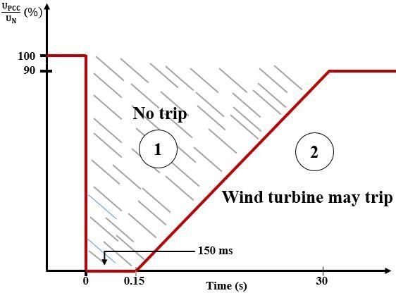
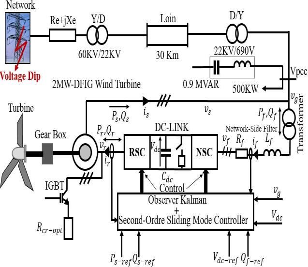
Received: February 22, 2021. Revised: May 27, 2021. 90

 3. Description and equations of the system
 3.1 System description

 Fig.1. Shows the overall schematic of the
 proposed electrical installation of a wind system
 connected to the electrical network. It is divided into
 two parts: the first mechanical part contains wind
 turbine, gearbox, and the second electrical part
 contains DFIG, electrical converters, DC-LINK, and
 grid side filter. For the electrical part, DFIG is
 connected to the utility network directly via
 its stator and indirectly through its rotor with the
 intermediary of converters, DC-LINK, and grid side
 Figure. 1 An overall diagram of a wind power system filter.
 connected to the electricity network
 3.2 Rotor-side converter equations
of the DFIG during a voltage dip at the limitation of
the parameters influenced by this fault.The next The asynchronous rotating d-q reference frame is
sections of the paper is organized as shown below. used to model the DFIG with the direct -axis oriented
In section 2, we start with the definition and along the stator flux position is given in Eqs. (1) to
representation of the different zones of the specific (5). In this direction, the decoupled control of the
network code in which the wind power system is active and reactive powers of the stator is attained.
connected. Section 3 deals with the description and The reference frame is rotating with angular speed .
equations of the system. In section 4, the SOSMC The voltages equations are:
strategy and the KO are represented, synthesized and
applied on the wind system. The results of the = + ̇ − (1)
MATLAB/Simulink simulation using a DFIG-2MW
wind turbine with the addition of the PPM = + ̇ + (2)
components are presented in the last section; these
results are compared and discussed with the existing = + ̇ − (3)
strategies in the literature [10, 11-13].
 = + ̇ + (4)
2. Specific network code
 Wind farms are kept connected and sustain the Where slip speed is the difference between
network during and after a fault by following a stator angular speed and the product of the
required network code. The network code to be number of pairs of poles p and rotor speed as
respected in this paper is given in Fig. 1. Zone 1 indicated in Eq. (5):
indicates the region where there is no tripping and
the wind farm remains connected to the network, = − (5)
even the voltage of the common network coupling
point has dropped to zero. Zone 2 indicates the The flux equations are:
tripping of the wind farm.
 = + (6)

 = + (7)

 = + (8)

 = + (9)

 The instantaneous expressions of the different
 powers involved in the new d-q frame are:
 Figure. 2 Voltage dip requirement

International Journal of Intelligent Engineering and Systems, Vol.14, No.5, 2021 DOI: 10.22266/ijies2021.1031.09
Received: February 22, 2021. Revised: May 27, 2021. 91

 = 1.5( + ) (10) From the observation of Eqs. (23) and (24), we
 arrive at a decoupled power control, where the
 = 1.5( − ) (11) component iqr the rotor current controls the active
 power. The reactive power is operated by the direct
 = 1.5( + ) (12) component idr. By rearranging Eqs. (3) and (4), we
 can deduce a formula of rotor currents as a function
 = 1.5( − ) (13) of rotor voltages in Eqs. (25) and (26).

The electromagnetic torque equation is given by: = + − (25)

 = 1.5 ( − ) (14) = + + +

 (26)
 The orientation of the stator flux vector along the
d-axis is to help control the electrical output of the 2
 Where, = 1 − is the leakage factor and,
wind power system. This orientation will be done

with a real DFIG model; taking into consideration =1−
 is the slip. So the dynamic of the rotor
the stator resistance. currents is expressed in the Eqs. (27) and (28):
 = = 0 (15) 1

 = ( − + ) (27)

And the stator voltages are reduced to: 1
 = ( − − − )

 = + ̇ (16) (28)

 = + (17) In established regime, the first terms derived
 from both Eqs. (25) and (26) are null and we can
 write:
 Suppose that the power supply network is stable,
leading to a constant stator flux and a new stator
voltage value: = − (29)

 = (18) = + +
 (30)

 = + (19) 3.3 Network-side converter equations

Substitute (15) in Eqs. (6), (7) and (14) we get: In this section, we are interested in modelling the
 connection of the NSC to the electricity network via
 the Rf Lf filter. Fig.3. illustrates the electrical model
 = − (20)
 of the Rf Lf connection filter.
 From Fig. 3, we can write the following

 = − (21) expressions in the three-phase reference frame,

 according to Kirchhoff's laws:

 = −1.5 (22) 1
 1 = − 1 −
 + 1 (31)

 By replacing stator currents with their 2
expressions in the Eqs. (10) and (11), we find: 2 = − 2 − + 2 (32)

 2 2 2 3
 = 1.5(
 −
 +
 ) (23) 3 = − 3 −
 + 3 (33)

 2 Where vg is the network voltage, if is network-
 = 1.5( − ) (24)
 filter current, and vf is the network filter voltage
 supplied from the grid-side converter. By
International Journal of Intelligent Engineering and Systems, Vol.14, No.5, 2021 DOI: 10.22266/ijies2021.1031.09
Received: February 22, 2021. Revised: May 27, 2021. 92

 Where Pcdc instantaneous active power through
 the capacitor, Pr rotor Active Power, Pf filter Power,
 pfilter_loss power loss in the filter, pconv_loss power loss
 in the converts RSC and GSC, pdc_loss power loss in
 the DC-LINK capacitor .

 = − − ( _ + _ + _ )

 Figure. 3 Electric model of the filter (43)
 ptot_loss : total loss
 applying Park's transformation to the three =

 = (44)
previous equations, we obtain:

 pfilter_loss , pconv_loss and pdc_loss will be taken into
 = + − + (34) account in this work because it significantly affects

 the system, especially in the event of a network dips.
 Substituting in the Power expressions from Eqs. (12),
 = +
 + + (35)
 (41) and (44), the voltage state model through the
 capacitor of the DC-LINK is written in Eq. (45):
 Where vfd ,vfq are the voltages at the output of
GSC and ifd ,ifq are the corresponding currents 1.5 + −
injected into the network. The active and reactive
 = ( ) −
 (45)

powers generated by the GSC are defined by:

 = 1.5( + ) (36) Rconv_loss : Represents the total switching loss of the
 converters
 = 1.5( − ) (37) Rdc_loss : Represents the losses in the capacitor of the
 DC- LINK
 The d-axis of the reference frame is oriented with With:
the network voltage angular position. Because the
amplitude of the network voltage is constant, vgd is • Rconv_loss= RRSC_loss // RNSC_loss
zero and vgq is constant.
 2 2
 • pconv_loss = ; pdc_loss=
 _ _
 = = 0 (38)
 pfilter_loss=Rf if 2
The Eqs. (34), (35), (36) and (37) become:

 = − + − +
 (39)

 = − − +
 (40)

 = 1.5( ) (41)
 (a)
 = −1.5( ) (42)

 From Eqs. (41) and (42), we observe that the
flow of the active and reactive powers between the
NSC and the network will be proportional to ifd and
ifq respectively.The electrical model in Fig. 4 (a)
illustrates the rotor, DC-LINK and converters
circuits with their losses. From Fig. 4 (b), the (b)
 Figure. 4 Real model of losses in: (a) the connection
equation of the power balance is written in Eq. (43). circuit and (b) associated power shaft
International Journal of Intelligent Engineering and Systems, Vol.14, No.5, 2021 DOI: 10.22266/ijies2021.1031.09
Received: February 22, 2021. Revised: May 27, 2021. 93

4. Principle of SOSMC 1
 1 = (− − − )
 The theory of SOSMC [6, 20] is an alternative to
 −
the problem of CSMC. In this approach, the term −
discontinuous no more appears directly in the
 1 −
synthesized control but in one of its superior 2 = (− + ) −

derivatives, which has the advantage of reducing the
chattering. The SOSMC was introduced to overcome Such that:
the chattering problem while maintaining the finite- 2 1 2 1
time convergence and robustness properties of 2
 ( ) = ̇ + 1̇ ; 2
 ( ) = ̇ + 2̇

conventional sliding mode controls and improving (51)
asymptotic precision. For this purpose, a super-
twisting algorithm (STA) control algorithm capable The STA is used to generate control laws [6].
of generating control laws of all second-order This algorithm for the SOSMC was proposed by
systems. EMELYANOV in 1990 contains two parts [6, 20]:

4.1 Stator powers control through the rotor-side 1

 converter = 1 − 1 | |2 ( ); ̇ 1 = − 1 ( )
 (52)
 The rotor currents that are related to the active
 1
and reactive powers by Eqs. (23) and (24) must
 = 1 − 2 | |2 ( ); ̇1 = − 2 ( )
follow the appropriate current references so that a
 (53)
SOSMC based on the Park reference frame above is
used. To ensure the convergence of the active and
 To ensure convergence within a short time, the
reactive powers of the DFIG stator in their
 parameter and must verify the following
references, the rotor current references d-q are
 inequalities:
defined by.

 2 2
 4 ( + )
 2 > ; ≥ ; | ̇ | < ; = 1,2
 − = ( − + − ) (46) 2 2 ( − )
 1.5

 2 On the other hand, the equivalent controls are
 − = − ( − − ) (47)
 1.5 calculated by setting to zero (49) and (50), as
 follows:
 The sliding surfaces representing the error
between the measured and references rotor currents
 − = + + +
are defined by:
 −

 (54)
 = − − ; = − − (48)
 −
 The dynamics of the sliding functions sq and sd − = + +
are defined by: (55)

 1 4.2 Control of the DC-LINK voltage and the
 ( ) = ( − − − reactive power of the filter through the

 − network-side converter

 ) − (49)
 The function of the network-side converter
 1 control is to ensure that the voltage of the DC-LINK
 ( ) = ( − + ) − is not changed and to annul the reactive power of the
 Rf Lf filter. this must be to synthesize control laws
 −

 (50) that are resistant to disturbances. In equation Eq.
 (45) of the voltage across the DC-LINK, the term
If we define functions F1 and F2 as follows: ptot_loss represent the total losses in the connection
 chain that must be available. This term is
 inaccessible for measurement with a real sensor. We,

International Journal of Intelligent Engineering and Systems, Vol.14, No.5, 2021 DOI: 10.22266/ijies2021.1031.09
Received: February 22, 2021. Revised: May 27, 2021. 94

therefore, suggest the use of a software sensor, Consequently, the system Eq. (58) is completely
which is called the KO to calculate an estimate of observable.
this term in real-time, and in a closed loop with the
controller. In addition, the use of an observer 4.2.2. Concept of the KO
minimizes the cost of the real sensor and since the
observers serve as a filter, measurement noise is The design of the KO is based on the recopy of
eliminated. the state model of the subsystem of Eq. (58) with a
 gain matrix of adjustment L, so the KO state model
4.2.1. Observability of the DC-LINK system is written in Eq. (59).

 First, before making the concept of the KO, it is ̂̇ = ̂ + + ( − ̂); ̂ = ̂; = ( 1 2 )
necessary to verify that the DC-LINK system is (59)
observable. Eq. (56) illustrates the dynamic model of
the voltage across the DC-LINK capacitor. We define the estimation error as follows:
 p(t)
 ̃ = − ̂ (60)
 1.5 (− − )
 = ( ) + −

 (56)

 The error dynamics are guided by the following
 For convenience, the variables were chosen as system:
follows (56).
 ̃̇ = ̇ − ̂̇ = ( − ) ̃ (61)
 2

 1 = ; 2 We introduced A’=A - LC , is chosen so that it is
 2
 ( + − + − + − ) a Hurwitz matrix b appropriate choice of vector L,
 =− ̃ = − ̂ is sure to converge exponentially to

 ( + − ) ( ) 0.From the Eqs. (59) and (61), th dynamics of the
 =− = estimated states are expressed by:

 ̂̇1 = ̂2 + + 1 ̃1 ; ̂̇2 = 2 ̃1 (62)
 The resulting state model representing the DC-
LINK voltage is now Eq. (57), where x2 represents
 4.2.3. DC-LINK voltage and filter reactive power
the term to be observed.
 control
 2 4.2.3.1. DC-LINK voltage control
 = ( 1 2 ) , = 1 = , = ;
 2
 = (01; 00) , The main objective of the proposed PIC is to

 = ( 0) , = (10) maintain the value of the voltage across the DC-
 LINK. Fig.5 shows the block diagram of the DC-
 ̇ 1 = 2 + ; ̇ 2 = ( ); = 1 ; = 1.5
 LINK voltage control. From Eq (56), we have:
 (57)
 = + ( ) = 1.5 (63)
 The previous state model can be rewritten in the
following general form: By adjusting the Pf power, it is then possible to
 control the Pcdc power in the capacitor and thus
 ̇ = + ; = (58) control the DC-LINK voltage. To do this, the powers
 p(t) and Pcdc must be known to determine Pf-ref. p(t)
 The observability of the DC-LINK system is is a perturbation seen by the control chain that will
verified by the determinant of the observability be measured by the KO. The power reference for the
matrix Oobs , this last must be different from zero: capacitor is related to the circulating reference
 current in the capacitor:
 10
 ( ) = ( ) = ( ) = 1 ≠ 0 − = − (64)
 01

 The transfer function of the DC-LINK system is:
International Journal of Intelligent Engineering and Systems, Vol.14, No.5, 2021 DOI: 10.22266/ijies2021.1031.09
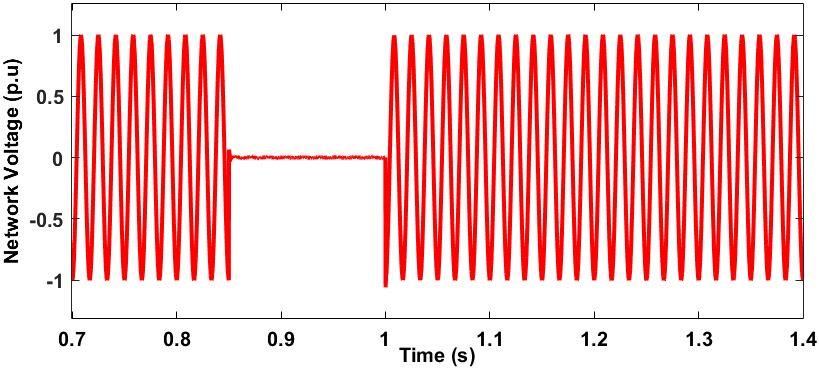
Received: February 22, 2021. Revised: May 27, 2021. 95

Laplace transform − 1 ( ) (71)
 ( ) 1 1
 = ⇒ ( )
 = (65) = 2′ − 2 | | ( ); ̇ 2′ =
 2

4.2.3.2. Filter Reactive Power Control − 2 ( ) (72)

 The filter currents that are related to the active To ensure convergence within a short time, the
and reactive powers exchanged between the NRC param and must verify the following inequalities:
and the network by Eqs. (41) and (42) must follow
the appropriate current references so that a SOSMC 4 ( + )
based on the above Park reference is used. To ensure > ; ≥ 2 ; | ̇ | < ; = 1,2
 ( − )
the convergence of the active and reactive powers
passing through the filter in their references, the
 On the other hand, the equivalent controls are
current reference ifd-ref of the filter is generated by
 calculated by setting to zero Eqs. (68) and (69), as
the voltage regulation loop Vdc and the current
 follows:
reference ifq-ref of the filter is defined by:
 −
 − = −
 −
 (66) − = − + +
 1.5
 (73)
 The sliding surfaces representing the error −
between the measured and references filter currents − = + +
 (74)
are defined by:

 = − − ; = − − (67) 5. Simulation and discussion of results
 The DFIG-based wind turbine, as illustrated in
 The dynamics of the sliding functions sfd and sfq Fig.1, is used to test the performance of the designed
are defined by: controller. The system in Fig.1 represents the

 grouping of thirty wind turbines and each of these

 ( ) = − + − +
 − has a capacity of 2 MW. The detailed simulation

 − model is developed in MATLAB using the

 (68) MATLAB/SIMULINK SimPowerSystems toolbox
 based on the DFIG-based wind turbine. The list of
 − parametrs values of DFIG, network filter, SOSMC,
 ( ) = − − + − (69)
 PI and KO is given in Tables 1, 2, and 3 following.
 A fault case is taken into account to analyse the
If we define functions H1 and H2 as follows: capacity of the DFIG to cross the fault using the non-
 linear SOSMC coupled with a KO designed for this
 − effect. The performance of the designed SOSMC is
 1 = − + − −
 also compared to existing strategies in the literature
 − [10, 11-13] in Section 5.2.1. In this case, study, a
 2 = − − −
 symmetrical voltage dip fault, which is the most
 critical fault on power networks and has a significant
Such that impact on the stability of wind farms that require
 2 1 2 1 support to cross it, is applied on the network. The
 2
 ( ) = ̇1 + ̇ ; 2
 ( ) = ̇2 + ̇
 fault is applied in the form of a symmetrical voltage
 (70) dip of 100% at t=0.85s for a duration of 0.15s, i.e.
 the fault is eliminated at t=1s .Simulation results
 The STA is used to generate control laws reals under SOSMC will be tested and analyzed for two
[6]: different scenarios:(1) network voltage dip fault
 without PPM, (2) network voltage dip fault with
 1
 PPM.
 = 1′ − 1 | |2 ( ); ̇ 1′ =

International Journal of Intelligent Engineering and Systems, Vol.14, No.5, 2021 DOI: 10.22266/ijies2021.1031.09
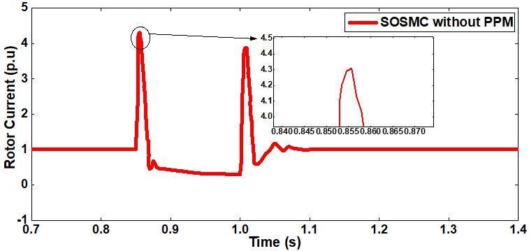
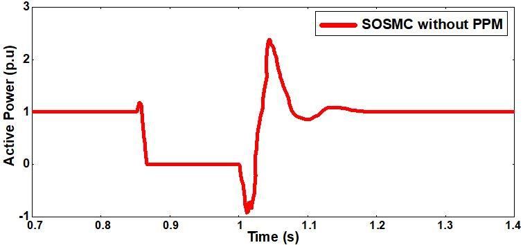
Received: February 22, 2021. Revised: May 27, 2021. 96

 Figure.5 DC-LINK voltage control loop

 Table 1. Simulation parameters for a DFIG
 Parameter Value
 Rated power = 2 MW
 Stator nominal voltage = 690 V
 Nominal frequency f = 50 Hz
 Number of pole pairs p=2
 Stator resistance = 0.023 .
 Rotor resistance = 0.016 .
 Stator inductance =0.18 .
 Rotor inductance = . p.u
 Mutual inductance M=2.9 p.u Figure.6 Network Voltage 60KV
 DC-LINK voltage =
* p.u= per unit
 Table 2. Parameters of network filter
 Parameter Value
 Inductance of the filter = . 3 p.u
 Resistance of the filter =0.003 p.u
 Resistance of the filter = 10−2 F

 Table 3. Parameters of SOSMC, PI and KO
 Parameter 1 2 1 2 1
 Value 1.5 200 50 1000 1.5
 Figure.7 Rotor current without passive protection
 Parameter 2 1 2 1 2 Using (Ir-ref =1p.u)
 Value 200 50 1000 2500 25000
 Parameter reaches high overcurrents at the onset of the fault
 Value 1.45 27.7 and reaches the value of 4.3 p.u with strong
 oscillations at the time of fault termination.
5.1 Behavior of the DFIG in situation of voltage As shown in Fig. 8, the active power response,
 dip without PPM its value reaches 1.1p. u when the fault occurs and
 then decreases rapidly to zero for the rest of the fault
 Fig. 7 shows the rotor current response during the duration. When the grid voltage recovers,with
fault with the strategy SOSMC. The rotor current SOSMC, it starts to decrease until 1.02s, then it starts
International Journal of Intelligent Engineering and Systems, Vol.14, No.5, 2021 DOI: 10.22266/ijies2021.1031.09
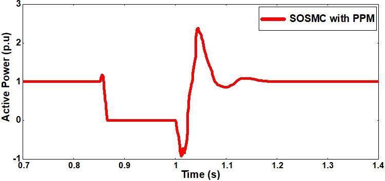
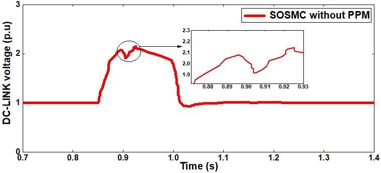
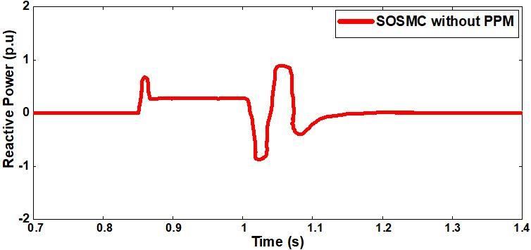
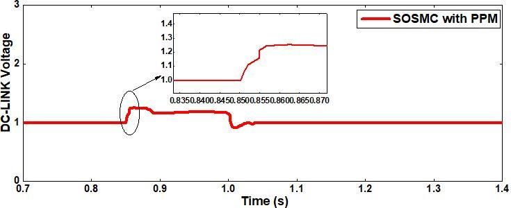
Received: February 22, 2021. Revised: May 27, 2021. 97 5.2 Behaviour of the DFIG in situation of voltage dip with PPM The performance of the wind system during a voltage dip with SOSMC strategie is unsatisfactory. In this section, we introduce a PPM that contains two crowbar and DC-chopper circuits to the control strategies used in the previous section to improve the performance of the wind power system during a voltage dip in the power network. Firstly, the Crowbar circuit is utilized to limit the rotor current Figure. 8 Power active without passive protection during the fault; it is placed between the rotor and Using (Ps-ref =1p.u) the RSC converter, as shown in fig.1; this consists of a resistor and an IGBT switch. Secondly, the ''DC- chopper'' circuit is used to limit the overvoltage at the terminals of the DC-LINK capacitor during the fault; it is connected in parallel with the DC-LINK. The optimal choice of the value of the crowbar resistance is given by [19]and expressed in Eq. (75). 2(Vr max s Ls )2 Rcr −opt = (75) 3.2Vs2 − 2Vr2max Concerning the operation of these two protection Figure. 9 Power Reactive without passive protection circuits is made by the flowchart of the activation- using (Qs-ref = 0p.u) inactivation management shown in Fig. 11. Fig. 12 shows the dynamics of the rotor current in the SOSMC strategy with the PPM activated. Indeed, with the addition of PPM to SOSMC, the system presents a better limitation of the rotor current peaks. When the fault occurs, the current reaches 1.45p.u, and when the network recovers the voltage, the current shows a low oscillation. As shown in Fig. 13 the response of the active power, its value reaches 1.1p. u when the fault occurs and then rapidly decreases to zero for the rest of the fault duration. When the mains voltage recovers, Figure. 10 DC-LINK voltage without passive protection with the SOSMC, it starts to decrease until 1.02s, using (Vdc-ref =1p.u) to increase again with a strong oscillation. Fig. 9 shows the response of the reactive power with SOSMC during a voltage dip. When the grid voltage is restored, the reactive power has a strong oscillation and a transient time to return to the pre- fault reference value of 150 ms . As shown in Fig. 10, the voltage response of the DC-LINK under the SOSMC strategy during a voltage dip. Between 0.85s and 1s, an overvoltage is observed across the DC-LINK capacitor with this strategy. While the overvoltage reaches to 2.1p.u with the SOSMC. However, with this strategy the DC-LINK voltage has a low oscillation regime after Figure. 11 Flowchart of the protection system the faults are eliminated. management International Journal of Intelligent Engineering and Systems, Vol.14, No.5, 2021 DOI: 10.22266/ijies2021.1031.09
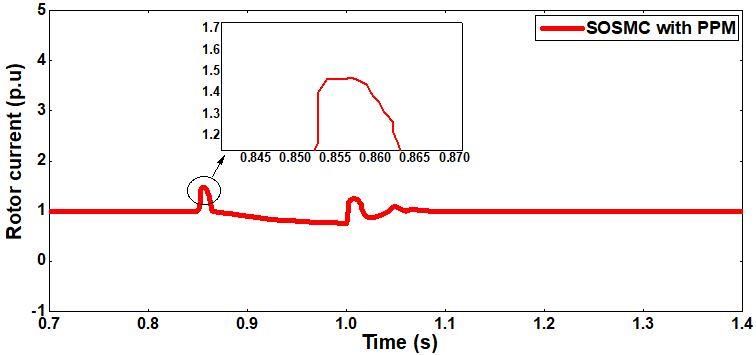
Received: February 22, 2021. Revised: May 27, 2021. 98

 then it starts to increase again with a strong
 oscillation .
 Fig. 14 shows the reactive power response with
 the SOSMC under activation of the PPM during a
 voltage dip. At the time of the fault, the reactive
 power increases and reaches a reduced value of
 0.6p.u with the control strategy. Then, during the
 voltage drop, the reactive power supplied by the
 wind system remains zero, which is why the power
 factor at the connection point is close to unity; thus,
 the system supports the grid with the fault, then after
 the recovery of the grid voltage with SOSMC the
 Figure. 12 Rotor current with passive protection reactive power reaches a small negative value of -
 using (Ir-ref =1p.u)
 1p.u at time 1.03s and reaches a steady state after a
 duration of 130ms with strong oscillations.
 As shown in Fig. 15, the DC-LINK voltage
 increases above its reference value of 1p.u at the time
 of the fault, which means that the capacitor has been
 overcharged. The SOSMC, under the same
 PPM ,limits however the overvoltage in satisfactory
 values of the DC-LINK capacitor. In addition, the
 oscillation behavior of the DC-LINK voltage after
 elimination of the fault remains by the low.

Figure.13 Power active with passive protection using (Ps- 5.2.1. Comparison to other methods in the
 ref =1p.u)
 Literature

 After demonstrating the peak limitation of the
 DFIG quantities during the voltage dip and the
 robustness of crossing the fault without destruction
 of the proposed controller, it is interesting to
 compare it with similar techniques in the literature to
 demonstrate its advantages and superiority. It is
 emphasized here that the above-mentioned
 techniques are not performed under the same
 constraints and conditions on the network in which
 the wind farm is connected, it is very rare to find
 many works performed under similar conditions.
 Figure. 14 Power Reactive with passive protection Based on this comparison, the proposed solution of
 using (Qs-ref = 0 p.u) the SOSMC with KO has robustness at the point of
 spike limitation and low oscillation. Thus, the
 Adaptadtive Backstepping controller (ABC) with
 High Gain Observer (HGO) presented by
 O.S.Adekanle (2018) [13] has Moderate-low
 Robustness against peaks limitation than our
 Technical. Also, the proposed solution has a better
 limitation of rotor current and DC-LINK voltage
 values during a voltage dip, compared to adaptive
 backstepping with a high gain observer [13], sliding
 mode [11], and proportional-integral controls [11].
 Table 4 shows a synthesis of the performance
 characteristics of the published controllers and our
 Figure.15 DC-LINK voltage with passive protection proposal. Based on this comparison, the superiority
 using (Vdc-ref =1p.u) of SOSMC-KO with PPM is proven.

International Journal of Intelligent Engineering and Systems, Vol.14, No.5, 2021 DOI: 10.22266/ijies2021.1031.09
Received: February 22, 2021. Revised: May 27, 2021. 99

 Table 4. The comparison between our results and other methods published
 Publication Technic With PPM during Robustness Oscillation at
 paper methods voltage dip against peaks the time of
 limitation fault
 Ir (pu) Vdc (pu)
 elimination
 N.H.Saad PIC 3.5 1.11 Not robust High
 (2015)[11]
 N.H.Saad SMC 5 0.1 Not robust High
 (2015)[11]
 O.S.Adekanle ABC 2.2 0.41 Moderate-robust low
 (2018)[13]
 Our Proposed SOSMC 1.45 1.2 Robust Low
 technique

6. Conclusion implementation of the proposed strategy. The
 following appendix presents the definitions of all the
 This paper deals with the modelling and control variables used in this paper.
of a DFIG taking into account all stator parameters
to bring the system closer to reality for the real active
 Conflicts of Interest
and reactive power equations. It also minimizes rotor
current and DC-LINK voltage surges and improves The authors declare no conflict of interest
reactive power in the case of a voltage dip in the
network. This modification gives safe and accepted Author Contributions
results in simulation, which is not the case of many
 Azeddine Loulijat and Najib Ababssi performed
researchers who previously neglected it.
 the study of SOSMC strategie and KO and the
 A robust non-linear control technique using
 structure of the paper. Azeddine Loulijat modeled
SOSMC is used to control the active and reactive
 the proposed DFIG-based wind power system under
power through RSC and the DC-LINK voltage with
 MATLAB/SIMULINK. Azeddine Loulijat and
the reactive power through NSC of a network-
 Makhad Mohamed wrote the paper. Najib Ababssi
connected 2 MW wind power system. When a
 and Makhad Mohamed contributed to reviewing the
voltage dip is detected in the network this control
 paper. All authors read and approved the final
technique is combined with a KO is designed to
 manuscript.
estimate the power generated on the rotor side of the
DFIG, the power losses in the RSC, NSC converters,
 References
and the DC-LINK capacitor to make the control
strategy more efficient and without the influence of [1] O. S. Adekanle, M. Guisser, E. Abdelmounim,
the measurement noise introduced by the sensors. and M. Aboulfatah, “Nonlinear Controller with
 A PPM includes crowbar and DC-chopper is Rotor Crowbar and DC-Chopper Fault Ride
added to the control technique used to increase the Through Technique for Grid-Connected
results found show that the addition of the PPM was Doubly-Fed Induction Generator”,
able to reduce the rotor current and bring the DC- International Review of Automatic Control, Vol.
LINK voltage below acceptable values during the 11, No. November, pp. 281-292, 2018.
fault. [2] A. M. Eltamaly, A. Alolah, and H. M. Farh, “3
 The performance of the designed SOSMC is also authors: Ali M. Eltamaly Mansoura University
compared to existing strategies in the literature in 145”, New Developments in Renewable Energy,
case network voltage dip fault with activation of the 2013.
PPM capacity of the system to overcome the fault in [3] C. O. F. Dfig, “Control of Dfig”, Power Eng.,
the 60KV electrical network.. No. February, 2003.
 The SOSMC is able to limit the current [4] M. Chakib, T. Nasser, and A. Essadki,
overshoot to less than 2p.u and DC-LINK “Comparative study of active disturbance
overvoltage less than or equal to 1.5 p.u during the rejection control with RST control for variable
voltage dip. wind speed turbine based on doubly fed
 The topic of our future research may include the induction generator connected to the grid”, Int.
development of an non-linear Adaptive Direct J. Intell. Eng. Syst., Vol. 13, No. 1, pp. 248-258,
Power Controllers with PPM for DFIG against the 2020.
asymmetrical voltage dips and the hardware [5] A. Touati, E. Abdelmounim, M. Aboulfatah, R.
International Journal of Intelligent Engineering and Systems, Vol.14, No.5, 2021 DOI: 10.22266/ijies2021.1031.09
Received: February 22, 2021. Revised: May 27, 2021. 100

 Majdoul, and A. Moutabir, “Design of an Mppt turbines: A comprehensive review of fault ride-
 based on the torque estimator for variable speed through strategies”, Renew. Sustain. Energy
 turbines”, In: Proc. 2015 Int. Conf. Electr. Inf. Rev., Vol. 45, pp. 447-467, 2015.
 Technol. ICEIT 2015, No. 1, pp. 166-171, 2015. [16] I. Erlich, H. Wrede, and C. Feltes, “Dynamic
[6] A. Touati, E. Abdelmounim, M. Aboulfatah, A. behaviour of DFIG-based wind turbines during
 Moutabir, and R. Majdoul, “Improved strategy grid faults”, IEEJ Trans. Ind. Appl., Vol. 128,
 of an MPPT based on the torque estimator for No. 4, pp. 1195-1200, 2008.
 variable speed turbines”, Int. Rev. Model. [17] Y. Shen, B. Zhang, T. Cui, J. Zuo, F. Shen, and
 Simulations, Vol. 8, No. 6, pp. 620-631, 2015. D. Ke, “Novel Control of DFIG with ESD to
[7] I. Yasmine, E. B. Chakib, and B. Badre, Improve LVRT Capability and to Perform
 “Improved Performance of DFIG-generators Voltage Support during Grid Faults”, In: Proc.
 for Wind Turbines”, Int. J. Pow. Electro. Driv. of 1st IEEE Int. Conf. Energy Internet, pp. 136-
 Syst., Vol. 9, No. 4, pp. 1875-1890, 2018. 141, 2017.
[8] W. Srirattanawichaikul, S. [18] S. Q. Bu, W. Du, H. F. Wang, and S. Gao,
 Premrudeepreechacharn, and Y. Kumsuwan, “Power angle control of grid-connected doubly
 “A comparative study of vector control fed induction generator wind turbines for fault
 strategies for rotor-side converter of DFIG wind ride-through”, IET Renew. Power Gener., Vol.
 energy systems”, In: Proc. of 2016 13th Int. 7, No. 1, pp. 18-27, 2013.
 Conf. Electr. Eng., 2016. [19] J. Yang, J. E. Fletcher, and J. O’Reilly, “A
[9] R. Pena, J. C. Clare, and G. M. Asher, “Doubly series-dynamic-resistor-based converter
 fed induction generator using back-to-back protection scheme for doubly-fed induction
 PWM converters and its application to generator during various fault conditions”,
 variablespeed wind-energy generation”, IEE IEEE Trans. Energy Convers., Vol. 25, No. 2,
 Proc. Electr. Power Appl., Vol. 143, No. 3, pp. pp. 422-432, 2010.
 231-241, 1996. [20] C. Zhang, S. V. Gutierrez, F. Plestan, and J. De
[10] J. Morren and S. W. H. de Haan, “Ridethrough León-Morales, “Adaptive super-twisting
 of wind turbines with doubly-fed induction control of floating wind turbines with collective
 generator during a Voltage dip”, IEEE Trans. blade pitch control”, IFAC-PapersOnLine, Vol.
 Energy Convers., Vol. 20, No. 2, pp. 435-441, 52, No. 4, pp. 117-122, 2019.
 2005.
[11] N. H. Saad, A. A. Sattar, and A. E. A. M. Appendix
 Mansour, “Low Voltage ride through of
 Common coupling point voltage
 doubly-fed induction generator connected to the
 grid using sliding mode control strategy”, Network voltage
 Renew. Energy, Vol. 80, pp. 583-594, 2015. DC-link voltage
[12] O. Adekanle, M. Guisser, E. Abdelmounim, IGBT Insulated-Gate Bipolar Transistor
 and M. Aboulfatah, “Adaptive backstepping Y Star coupling
 control of grid-connected doubly-fed induction D Delta coupling
 generator during grid Voltage dip”, In: Proc. of , Filter Active and Reactive Power
 2017 Int. Conf. Electr. Inf. Technol, Vol. 2018- , Direct and quadrature stator voltage
 Janua, pp. 1-6, 2018. , Direct and quadrature rotor voltage
[13] O. S. Adekanle, M. Guisser, E. Abdelmounim, , Direct and quadrature stator current
 and M. Aboulfatah, “Nonlinear controller with , Direct and quadrature rotor current
 rotor crowbar and DC-chopper fault ride , Stator flux linkage
 through technique for grid-connected doubly-
 , Roror flux linkage
 fed induction generator”, Int. Rev. Autom.
 Control, Vol. 11, No. 6, pp. 281-292, 2018. , Stator and rotor resistance
[14] F. Mwasilu, J. J. Justo, K. S. Ro, and J. W. Jung, , Slip and stator angular velocity
 “Improvement of dynamic performance of p Number of pairs of machine poles
 doubly fed induction generator-based wind , Stator and rotor self inductance
 turbine power system under an unbalanced grid M Mutual inductance
 Voltage condition”, IET Renew. Power Gener., , Stator Active and Reactive Power
 Vol. 6, No. 6, pp. 424-434, 2012. , Rotor Active and Reactive Power
[15] J. J. Justo, F. Mwasilu, and J. W. Jung, Electromagnetic torque
 “Doubly-fed induction generator based wind , Resistance end self of filter
International Journal of Intelligent Engineering and Systems, Vol.14, No.5, 2021 DOI: 10.22266/ijies2021.1031.09
Received: February 22, 2021. Revised: May 27, 2021. 101

 , , Controller constants of RSC
 L Observer gain
 , , Controller constants of NSC

International Journal of Intelligent Engineering and Systems, Vol.14, No.5, 2021 DOI: 10.22266/ijies2021.1031.09
You can also read