Keysight Technologies - M8195A 65 GSa/s Arbitrary Waveform Generator and M8197A Multi-Channel Synchronization Module Data Sheet Version 3.0 ...
←
→
Page content transcription
If your browser does not render page correctly, please read the page content below
Keysight Technologies
M8195A 65 GSa/s Arbitrary Waveform Generator
and
M8197A Multi-Channel Synchronization Module

                                         Data Sheet
                                         Version 3.0
02 | Keysight | M8195A 65 GSa/s Arbitrary Waveform Generator and M8197A Multi-Channel Synchronization Module - Data Sheet

M8195A at a Glance
Go where you have never been able to test before: with real-time mode, sequencing and
deep memory - explore your possibilities.
  –– Sample rate up to 65 GSa/s (on up to 4 channels)
  –– Analog bandwidth: 25 GHz
  –– 8 bits vertical resolution
  –– Up to 16 GSa of waveform memory per AXIe module
  –– 1, 2 or 4 differential channels per 1-slot high AXIe module (number of channels is
     software upgradeable)
  –– Multi-module synchronization
      –– Up to 16 channels per 5-slot AXIe chassis1
  –– Advanced 3-level sequencing with external dynamic control1
  –– Load new waveforms on-the-fly without interrupting the playback of the previous
     one1 (“memory ping-pong”)
  –– Amplitude up to 1 Vpp(se), 2 Vpp(diff), voltage window -1.0 … +3.3V
  –– trise/fall 20%/80% 18 ps (typ). With pre-distortion applied 12 ps (typ)
  –– Ultra low intrinsic jitter (RJrms < 200 fs)
  –– Built-in frequency and phase response calibration for clean output signals
  –– Up to 64-tap FIR filter in hardware for frequency response compensation
  –– Up to 2 markers with 1 sample resolution (markers don’t reduce vertical resolution)
  –– Embedded DSP enables real-time waveform and impairment generation

Speed your test by up to 100 times with unique real-time mode.

Key Applications
As devices and interfaces become faster and more complex, the M8195A AWG gives
you the versatility to create the signals you need for digital applications, optical and
electrical communication, advanced research, wideband radar and satcom.
  –– Coherent optical – a single M8195A module can generate two independent I/Q
     baseband signals (dual polarization = 4 channels) at up to 32 GBaud (and beyond).
  –– Multi-level / Multi-channel digital signals – generate NRZ, PAM4, PAM8, DMT, etc.
     signals of up to 32 Gbaud. Embed/de-embed channels, add jitter, ISI, noise and
     other distortions.
  –– Physics, chemistry and electronics research – generate any mathematically defined
     arbitrary waveforms, ultra-short yet precise pulses and extremely wideband chirps.
  –– Wideband RF/µW – generate extreme wideband RF signals with an instantaneous
     bandwidth of DC to 25 GHz for aerospace/defense/communication applications

Coherent optical applications
The M8195A supports leading edge research for 100 Gb/s, 400 Gb/s and 1 Tb/s
optical transmission systems that require a very wideband electrical stimulus with a
variety of complex modulation formats from QPSK to nQAM to OFDM at symbol rates up
to 32 GBaud and beyond.

In order to drive dual-polarization systems, the M8195A has 4 independent, yet precisely
synchronized analog output channels in a single module. Since all 4 channels are
generated by the same instrument without any external circuitry, precise synchronization
down to the femto-second-range can be achieved and maintained.

                                                                                                                    Figure 1. 16QAM @ 32 GBaud.

1. Available with M8195A plus M8197A.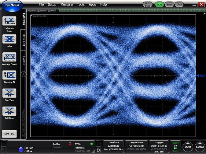
03 | Keysight | M8195A 65 GSa/s Arbitrary Waveform Generator and M8197A Multi-Channel Synchronization Module - Data Sheet
The M8195A uses digital pre-distortion techniques for frequency- and phase-response
compensation of the AWG output and any external circuits. These are required in order
to achieve a clean signal at the device under test.
Distortions generated by cables, amplifiers, etc. can also be compensated by embedding
/de-embedding the S-parameters of the respective circuits or by performing an in-situ
calibration using Keysight 81195A Optical Modulation Generator software.
In conjunction with the 81195A Optical Modulation Generator software clean signals and
signals stressed with impairment patterns can be generated both offline on a PC or in
real-time using the hardware DSP block, which allows the parameters of the waveform
(e.g., the pulse shaping filter coefficients) and impairment generation to be adjusted at
Figure 2. Optical Modulation Generator Software
run-time without downloading a new waveform.
Multi-level/multi-channel digital signals
Increasing the data throughput on digital interfaces has traditionally been accomplished
by increasing the data rate or by increasing the number of parallel signals. However, at
a certain point, it is more cost-effective to consider multi-level signaling techniques.
Examples are high-speed backplane connections using PAM4 or PAM8, and also
technologies in the mobile application space.
The M8195A is ideally suited to address those multi-level/multi-channel interfaces using
any standard or custom data format. The flexibility of the waveform generation at highest
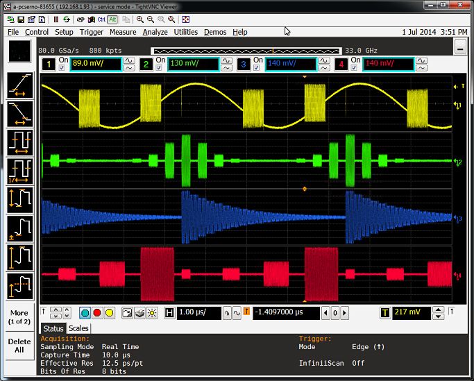
speeds, combined with excellent intrinsic jitter performance makes the M8195A truly a Figure 3. 4 PAM4 signal at 28 GBaud (= 56 Gbit/s).
future-proof instrument – independent of the direction technology is moving.
At data rates of multiple Gb/s, the effect of cables, board traces, connectors etc. have
to be taken into account in order to generate the desired signal at the test point of
the device under test. The M8195A incorporates digital pre-distortion techniques for
frequency- and phase response compensation of the AWG output and any external circuit
to generate the desired signal at the device under test. Channels can be embedded/
de-embedded if the S-parameters of the respective circuits are provided.
With up to 4 differential output channels per 1-slot AXIe module and the ability to
synchronize multiple modules, the M8195A is well-suited to stimulate multi-lane
high-speed interfaces in a very economic fashion.
Figure 4. 32 Gb/s PRBS 211-1 showing 138 fs RJrms.
With the integration of the M8195A AWG into the M8000 Series of BER test solutions,
Keysight allows you to address your high-speed digital receiver test needs with the
M8070A software platform and choose the BERT or AWG that best meets your needs.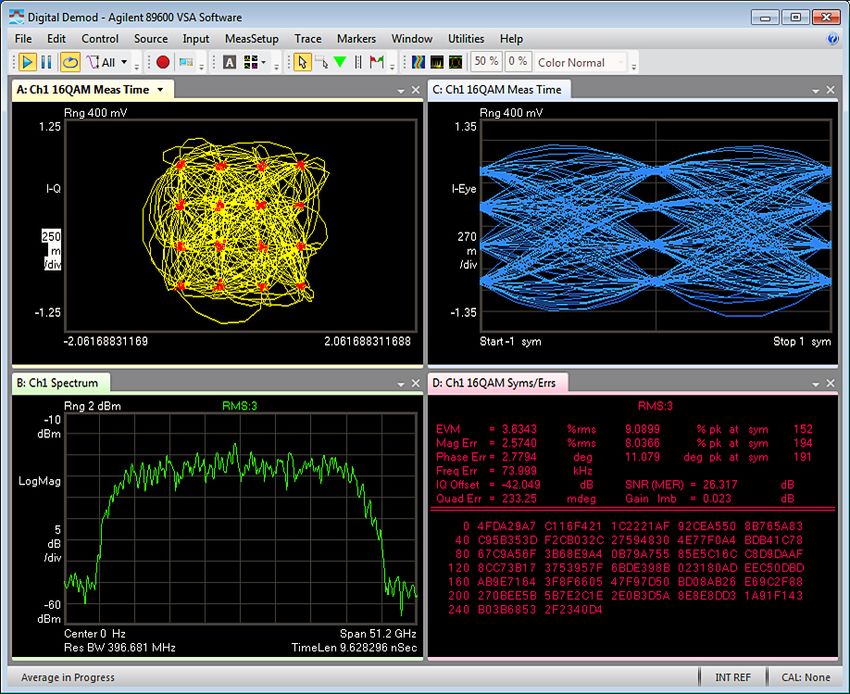
04 | Keysight | M8195A 65 GSa/s Arbitrary Waveform Generator and M8197A Multi-Channel Synchronization Module - Data Sheet

Physics, chemistry and electronics research
You can generate any arbitrary waveform that you can mathematically describe (e.g. in
MATLAB) and download it directly to the M8195A. This includes ultra-short yet precise
pulses down to ~100 ps pulse width or extremely short, yet wideband RF pulses and
chirps.

In conjunction with the M8197A synchronization module, these signals can be triggered
from external sources with very low jitter.

Wideband RF/µW signals
                                                                                                                    Figure 5. 100 ps pulse with 17 ps risetime.
The M8195A can address wideband wireless, EW and comms/satcom applications where
extremely wide instantaneous bandwidth (DC to 25 GHz) and fast frequency hopping are
critical parameters.

With built-in frequency and phase calibration, it is straight forward to generate wideband
multi-tone signals with a flat frequency response up to 25 GHz.

Wideband wireless signals with any modulation scheme (e.g. nPSK, nQAM, APSK, OFDM,
etc.) can be generated directly at carrier frequencies of up to 25 GHz. In many cases,
this saves an additional up-conversion stage (e.g. in case of IEEE 802.11ad) or enables
waveform generation directly at the carrier frequency.

Note that the available frequency range depends on the number of channels that are                                  Figure 6. Multi-tone signal from 10 GHz to 15 GHz.
used simultaneously as well as the amount of memory per channel (see sample memory
modes in this document).

                                                                                                                    Figure 7. Four different pulsed signals up to 25 GHz.
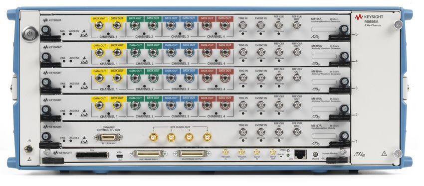
05 | Keysight | M8195A 65 GSa/s Arbitrary Waveform Generator and M8197A Multi-Channel Synchronization Module - Data Sheet

M8197A
The M8197A is a synchronization module for up to four M8195A modules. Using the M8197A, a fully synchronous system with up to
16 channels per AXIe 5-slot chassis can be realized. The M8197A also provides a dynamic control input/general purpose output that
can be used with one or more M8195A modules. Trigger-to-output delay accuracy is improved when using the M8197A trigger input
(see timing characteristics paragraph).

Figure 8. M8197A, front panel view and system with 16 synchronized channels (4x M8195A modules and 1x M8197A module)

06 | Keysight | M8195A 65 GSa/s Arbitrary Waveform Generator and M8197A Multi-Channel Synchronization Module - Data Sheet

Software
The basic functionality of the M8195A is controlled from a soft front panel application
running on the AXIe embedded controller or external PC or laptop. In addition to basic
settings such as sample clock rate, output amplitudes, etc., the soft front panel offers
functionality to:

  –– Load waveforms from files
  –– Generate standard waveforms (sine, square, etc.)
  –– Generate multi-tone waveforms
  –– Generate complex modulated waveforms (nPSK, nQAM, etc.)
  –– Generate binary and multi-level digital waveforms
  –– Generate serial data waveforms
  –– Control FIR filters

In addition to the soft front panel, the M8195A can be controlled via SCPI and
IVI-COM remote programming interfaces.

External software applications that can be used to generate and download waveforms
directly to the M8195A via SCPI or IVI-COM include MATLAB, LabView, C++, C# or any
other .NET language.

The M8195A is integrated into the following Keysight software applications:

  –– M8070A - system software for M8000 Series of BER test solutions
  –– M8085A - MIPI® receiver test solutions
  –– 81195A - optical modulation generator software
  –– M9099A - waveform creator application software
  –– W146xA - SystemVue electronic system-level design software

For additional information see the respective data sheets.
07 | Keysight | M8195A 65 GSa/s Arbitrary Waveform Generator and M8197A Multi-Channel Synchronization Module - Data Sheet

Configuration
The following products/options are available.

 Product number          Description                                                                                        Comment
 M8195A-001              1 channel, 65 GSa/s, 2 GSa per module                                                              Including local start-up assistance
 M8195A-002              2 channel, 65 GSa/s, 2 GSa per module                                                              and one 50 Ω termination for each
 M8195A-004              4 channel, 65 GSa/s, 2 GSa per module                                                              channel
 M8195A-16G              Upgrade to 16 GSa per module                                                                       Software license
 M8195A-SEQ              Sequencer functionality per module                                                                 Software license
 M8195A-FSW              Fast switching per module                                                                          Software license
 M8195A-1A7              ISO 17025 report
 M8195A-Z54              Z54 calibration report
 M8195A-BU1              Pre-configured system consisting of one M9505A 5-slot AXIe Chassis with USB Option and
                         one M9536A AXIe Embedded PC Controller
 M8195A-BU2              Pre-configured system consisting of one M9502A 2-slot AXIe Chassis with USB Option
 M8195A-BU3              Pre-configured system consisting of one M9502A 2-slot AXIe Chassis with USB Option and
                         one M9536A AXIe Embedded PC Controller
 M8197A                  Synchronization module for up to four M8195A modules                                               Including four synchronization
                                                                                                                            cables
 M8195S                  Pre-configured Arbitrary Waveform Generator System including one M8197A                            In addition to the required modules,
                                                                                                                            a local start-up assistance, one
                                                                                                                            50 Ω termination for each channel
                                                                                                                            and an AXIe chassis with an
                                                                                                                            embedded controller or external PC
                                                                                                                            connectivity will automatically be
                                                                                                                            added.

Upgrade options for M8195A

 Product number          Description                                                                                        Comment
 M8195AU-U02             Upgrade from 1 ch. to 2 ch.                                                                        Software license
 M8195AU-U04             Upgrade from 2 ch. to 4   ch.1                                                                     Software license
 M8195AU-16G             Upgrade to 16 Gsa per module                                                                       Software license
 M8195AU-SEQ             Sequencer functionality per module                                                                 Software license
 M8195AU-FSW             Fast switching per module                                                                          Software license

1. For an upgrade from 1 to 4 channels, both M8195AU-U02 and M8195AU-U04 are required.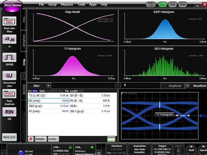
08 | Keysight | M8195A 65 GSa/s Arbitrary Waveform Generator and M8197A Multi-Channel Synchronization Module - Data Sheet

Accessories
In order to be operational, an AXI chassis plus either an embedded controller or external PC or laptop are required in addition to one or
more M8195A/M8197A modules. (See http://www.keysight.com/find/AXIe for more details.)

 Product number          Description                                                                                        Comment
 M9502A-U20              2 slot AXIe chassis with USB option
 M9505A-U20              5 slot AXIe chassis with USB option
 M9536A                  AXIe embedded controller
 8121-1243               Cable-Assembly USB Type A-MINI B 28-AWG 5-Conductor 2-M-LG PVC
 M9048A                  PCIe® desktop card adapter Gen 2 x 8
 Y1202A                  PCIe cable for M9048A desktop adapter
 M8195A-810              Matched cable pair for M8195A AWG, 2.92 mm
 M8195A-820              Termination 50 Ω, 26.5GHz

Software
 Product number          Description                                                                                        Comment
 81195A                  Optical Modulation Generator Software                                                              Free to download
 81195A-RSP              Real-Time Signal Processing
                                                                                                                            requires 81195A
 81195A-OSP              Optical Signal Properties
 M8070A-0TP              System Software for M8000 Series of BER Test Solutions,
                         Transportable, Perpetual License
 M8070A-0NP              System Software for M8000 Series of BER Test Solutions,
                         Network/Floating, Perpetual License
 M8070A-1TP              DUT Control Interface, Transportable, Perpetual License
 M8085A-CT1              MIPI C-PHY sm Editor for M819xA AWG, transportable, perpetual License
 M8085A-CN1              MIPI C-PHY Editor for M819xA AWG, network/floating, perpetual License
 M8085A-CTA              MIPI C-PHY Calibration, Conformance an Characterization Procedures for M819xA AWG,
                         Transportable, Perpetual License
 M8085A-CNA              MIPI C-PHY Calibration, Conformance and Characterization Procedures for M819xA AWG,
                         Network/Floating, Perpetual License
                                                                                                                            requires M8070A license
 M8085A-DT1              MIPI D-PHY sm Editor for M819xA AWG, transportable, perpetual License
 M8085A-DN1              MIPI D-PHY Editor for M819xA AWG, network/floating, perpetual License
 M8085A-DTA              MIPI D-PHY Calibration, Conformance and Characterization Procedures for M819xA AWG,
                         transportable, perpetual License
 M8085A-DNA              MIPI D-PHY Calibration, Conformance and Characterization Procedures for M819xA AWG,
                         Network/Floating, Perpetual License
 N6171A-M02              MATLAB license (standard)
 N6171A-M03              MATLAB license (extended)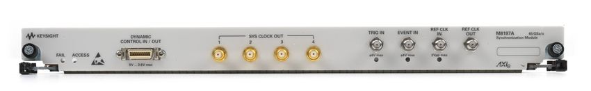
09 | Keysight | M8195A 65 GSa/s Arbitrary Waveform Generator and M8197A Multi-Channel Synchronization Module - Data Sheet

Specifications
General characteristics
                                                         M8195A
 Sample rate                                             53.76 GSa/s to 65.00 GSa/s
                                                         or 26.88 GSa/s to 32.50 GSa/s (sample rate divider = 2)
                                                         or 13.44 GSa/s to 16.25 GSa/s (sample rate divider = 4)
 DAC resolution                                          8 bits
 Number of channels per M8195A module                    1, 2 or 4 (corresponds to Opt. 001, 002, 004)
                                                         Number of channels is software upgradable via license key

Sample memory
                                                         M8195A
 Internal sample memory                                  1 MSa per module
                                                         (for modes of operation see Sample memory modes table below)
 Extended sample memory                                  2 GSa per M8195A module (standard)16 GSa per M8195A module (with Option 16G)
                                                         (for modes of operation see Sample memory modes table below)
 Waveform granularity1
     Int. memory                                         128 samples
     Ext. memory, sample rate divider = 1                256 samples
     Ext. memory, sample rate divider = 2                128 samples
     Ext. memory, sample rate divider = 4                64 samples
 Minimum waveform length
     Int. memory                                         128 samples
     Ext. memory, sample rate divider = 1                1280 samples
     Ext. memory, sample rate divider = 2                640 samples
     Ext. memory, sample rate divider = 4                320 samples

Useable number of Channels with extended memory
 Option                Mode                                                                       Sample rate divider
                                                                       1                                    2                           4
                                                        53.76 GSa/s to 65.00 GSa/s           26.88 GSa/s to 32.50 GSa/s     13.44 GSa/s to 16.25 GSa/s
                                                             max. 16G memory                       max. 8G memory               max. 4G memory
 001     002    004    single   channel 2                              1                                    1                           1
                       single channel with marker                      1                                    1                           1
                       dual channel 2                                  1                                    2                           2
                       dual channel with    marker 2                   1                                    2                           2
                       dual channel duplicate                        N/A                                    2                           2
                       four channel 2                                  1                                    2                           4

1.   The length of waveform segments must be a multiple of the granularity.
2.   Unused channels can be used at full sample rate with internal memory.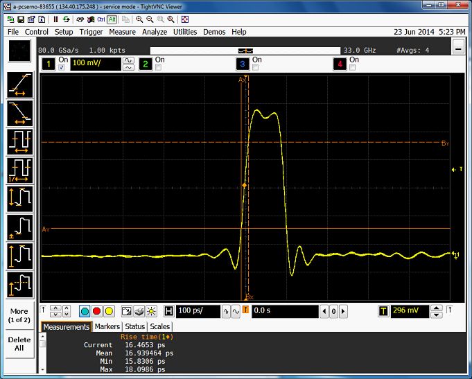
10 | Keysight | M8195A 65 GSa/s Arbitrary Waveform Generator and M8197A Multi-Channel Synchronization Module - Data Sheet

Sample memory modes
 Mode                  Available with        Sample memory           Sample memory        Max. sample       Interpolation 1   Max. output   Analog BW
                       option                (standard)              (with Opt. 16G)      rate                                frequency 2   (typ) (3 dB)
 1 ch, ext.mem.        001, 002, 004         2 GSa                   16 GSa               65 GSa/s          None              > 25 GHz      25 GHz
 1 ch, int. mem.       001, 002, 004         1 MSa                   1 MSa                65 GSa/s          None              > 25 GHz      25 GHz
 2 ch, ext.mem.        002, 004              1 GSa per ch.           8 GSa per ch.        32.5 GSa/s        2x                12.8 GHz      25 GHz
 2 ch, int.mem.        002, 004              512 KSa per ch.         512 KSa per ch.      65 GSa/s          None              > 25 GHz      25 GHz
 4 ch, ext.mem.        004                   0.5 GSa per ch.         4 GSa per ch.        16.25 GSa/s       4x                 6.4 GHz      25 GHz
 4 ch, int.mem.        004                   256 KSa per ch.         256 KSa per ch.      65 GSa/s          None              > 25 GHz      25 GHz

Frequency switching characteristics
                                                             M8195A
 Effective frequency switching time3
     with Option FSW                                         38 ps
     without Option FSW                                      > 505 µs

Out 1, 2, 3, 4
                                                             M8195A
 Output type                                                 Single ended4 or differential
 Bandwidth (3 dB, excl. sin(x)/x roll-off)                   25 GHz (typ)
 Rise/fall time5 (20% / 80%)                                 18 ps (typ)
 Impedance                                                   50 Ω (nom)
 Amplitude                                                   75 mVpp to 1.0 Vpp, single-ended into 50 Ω
                                                             150 mVpp to 2.0 Vpp, differential
 Amplitude resolution                                        200 µV (nom)
 DC amplitude accuracy 6                                     ±(2.5% +10 mV) (typ)
 Voltage window                                              -1.0 V to +3.7 V single-ended into 50 Ω
 Offset resolution                                           200 µV (nom)
 DC offset accuracy7                                         ± 20 mV (typ)
 Differential offset                                         In system adjustable to 0 mV
 Termination voltage window                                  -1.0 V to + 3.7 V
                                                             VOL ≤ 1.5 V: (low level - 500 mV) to (high level +1000 mV)
                                                             VOL > 1.5 V: low level to (high level +1000 mV)
 Total jitter, with pre-distortion                           6 ps (pp) at 32 Gb/s PRBS (nom)
 Random jitter,   RMS 8                                      200 fs (typ)

1.   Interpolation is performed by FIR filters in hardware. For 2x (4x) interpolation, samples are read from
     memory at a rate up to 32.5 GSa/s (16.25 GSa/s) and interpolated to a DAC sample rate of up to 65 GSa/s.
     For interpolation = none, the sample rate from memory is the same as the DAC sample rate.
2.   With default FIR configuration the maximum sample rate is calculated as 80% of Nyquist.
     With custom FIR configurations higher output frequencies can be achieved.
3.   Effective switching frequency is determined as 1/f max, with f max = f Sa(max) / 2.5
4.   Unused output must be terminated with 50 Ω to GND. In case the termination voltage is not GND, the unused
     output must be terminated to V Term.
5.   Sample rate 64 GSa/s, output amplitude 500 mVpp(se).
6.   Termination voltage = 0 V; adjusted at 23 °C ambient temperature, amplitude increases by 0.2%/°C (typ) for
     ambient temperature below 23 °C.
7.   Termination voltage = 0 V.
8.   10 GHz clock; 1 V ampl.; 60 GSa/s.
11 | Keysight | M8195A 65 GSa/s Arbitrary Waveform Generator and M8197A Multi-Channel Synchronization Module - Data Sheet
Out 1, 2, 3, 4 (continue)
M8195A
Harmonic distortions1,2
2nd harmonic -45 dBc (typ), fout < 3 GHz
-35 dBc (typ), fout = 3 GHz… 6 GHz
-30 dBc (typ), fout > 6 GHz
3rd harmonic -45 dBc (typ), fout < 1 GHz
-40 dBc (typ), fout = 1 GHz… 3 GHz
-35 dBc (typ), fout = 3 GHz… 6 GHz
-30 dBc (typ), fout > 6 GHz
Two-tone IMD1 -45 dBc (typ), fout1 = 990 MHz, fout2 = 1010 MHz
SFDR1 (excluding harmonic distortions)
In-band -80 dBc (typ), fout = 100 MHz, measured DC to 1 GHz
-70 dBc (typ), fout = DC…400 MHz, measured DC to 400 MHz
-48 dBc (typ), fout = DC…4 GHz, measured DC to 4 GHz
-53 dBc (typ), fout = 4 GHz…6 GHz, measured 4 GHz to 6 GHz
-53 dBc (typ), fout = 6 GHz…8 GHz, measured 6 GHz to 8 GHz
-50 dBc (typ), fout = 8 GHz…10 GHz, measured 8 GHz to 10 GHz
-46 dBc (typ), fout = 10 GHz…12 GHz, measured 10 GHz to 12 GHz
-50 dBc (typ), fout = 12 GHz…14 GHz, measured 12 GHz to 14 GHz
-42 dBc (typ), fout = 14 GHz…16 GHz, measured 14 GHz to 16 GHz
-42 dBc (typ), fout = 16 GHz…18 GHz, measured 16 GHz to 18 GHz
-42 dBc (typ), fout = 18 GHz…20 GHz, measured 18 GHz to 20 GHz
-48 dBc (typ), fout = 20 GHz…21 GHz, measured 20 GHz to 21 GHz
-42 dBc (typ), fout = 21 GHz…22 GHz, measured 21 GHz to 22 GHz
-40 dBc (typ), fout=22 GHz....24 GHz, measured 22 GHz to 24 GHz
-40 dBc (typ), fout=24 GHz....26 GHz, measured 24 GHz to 26 GHz
Adjacent band -48 dBc (typ), fout = DC…4 GHz, measured DC to 8 GHz
-48 dBc (typ), fout = 4 GHz…6 GHz, measured 3 GHz to 8 GHz
-34 dBc (typ), fout = 6 GHz…8 GHz, measured 4 GHz to 10 GHz
-34 dBc (typ), fout = 8 GHz…10 GHz, measured 6 GHz to 12 GHz
-46 dBc (typ), fout = 10 GHz…12 GHz, measured 8 GHz to 14 GHz
-42 dBc (typ), fout = 12 GHz…14 GHz, measured 10 GHz to 16 GHz
-32 dBc (typ), fout = 14 GHz…16 GHz, measured 12 GHz to 18 GHz
-30 dBc (typ), fout = 16 GHz…18 GHz, measured 14 GHz to 20 GHz
-40 dBc (typ), fout = 18 GHz…20 GHz, measured 16 GHz to 22 GHz
-35 dBc (typ), fout=20 GHz....22 GHz, measured 18 GHz to 24 GHz
-30 dBc (typ), fout=22 GHz....24 GHz, measured 20 GHz to 26 GHz
-28 dBc (typ), fout=24 GHz....25 GHz, measured 22 GHz to 27 GHz
-28 dBc (typ), fout=25 GHz....26 GHz, measured 23 GHz to 27 GHz
Amplitude flatness (at SMA connector, 3 ±2 dB (typ), fout= DC…10 GHz
compensated for sin(x)/x) +2 dB, -3 dB (typ), fout = 10…25 GHz (typ)
Connector type 2.92 mm “K-style” (female)
1. Sample rate 64 GSa/s, output amplitude 500 mVpp(se).
2. Measured with a balun (e.g. HL 9405).
3. Measured at Data Out.12 | Keysight | M8195A 65 GSa/s Arbitrary Waveform Generator and M8197A Multi-Channel Synchronization Module - Data Sheet
Phase noise
-70
-80
Phase noise (dBc/Hz)
-90
-100
100 MHz sine
-110
1 GHz sine
-120
10 GHz sine
-130
20 GHz sine
-140
-150
1.0E+03 1.0E+04 1.0E+05 1.0E+06 1.0E+07 1.0E+08
Offset frequency (Hz)
Figure 9. Nominal phase noise measured with a sample rate of 64 GSa/s, at Out 1, single ended, 500 mV amplitude
Frequency response
5
0
Frequency response (dB)
-5 Mathematically
compensated for
sin(x)/x
-10 Measured
-15
-20
-25
0 5 10 15 20 25 30
Frequency (GHz)
Figure 10. Nominal frequency response measured with a sample rate of 64 GSa/s and a multi-tone signal containing
frequencies from DC to 32 GHz with equal amplitudes13 | Keysight | M8195A 65 GSa/s Arbitrary Waveform Generator and M8197A Multi-Channel Synchronization Module - Data Sheet
ENOB
ENOB measured at 64 GSa/s using the sine fit method according to IEEE Std 1658-2011
with a sampling scope. Bandwidth is limited to maximum tone frequency, except for the
ones labled with Nyquist.
8.5
ENOB 25GHz Nyquist
ENOB 25GHz
8.0
ENOB 20GHz
ENOB 15GHz
7.5 ENOB 10GHz
ENOB 5GHz
7.0
6.5
ENOB
6.0
5.5
5.0
4.5
4.0
000E+00 5E+09 10E+09 15E+09 20E+09 25E+09
Carrier Frequency [Hz]
Figure 11. Nominal ENOB measured on a differential signal combined by a 50 GHz Balun Hyperlabs HL9405
with a sample rate of 64 GSa/s, internal clock and 500 mV amplitude at different bandwidths.
Markers
Two independent digital markers and their complements are available in single channel
with markers and dual channel with markers mode. The markers are available only for
channels on extended memory. They are provided on channel 3 and 4 on normal and
complement.
In all other modes, no markers are available.
Markers do not reduce vertical resolution.
The granularity of markers is one sample, a maximum of one rising and one falling edge
of a marker are possible within 128 samples.
Dual channel duplicate mode
In “Dual channel duplicate mode” the signal on channel 1 is duplicated on channel 2 and
the signal on channel 4 is duplicated on channel 3.
This mode allows differential signals to be generated with adjustable skew between
normal and complement.14 | Keysight | M8195A 65 GSa/s Arbitrary Waveform Generator and M8197A Multi-Channel Synchronization Module - Data Sheet
Run modes
M8195A and M8197A
Continuous
Int. Memory A waveform segment is continuously repeated
Ext. Memory A waveform segment/sequence/scenario is continuously repeated
Triggered
Int. Memory A waveform segment is looped continuously after a trigger event is received
Ext. Memory A waveform segment/sequence/scenario is generated once after a trigger event is received
Gated
Int. Memory A waveform segment is looped continuously after a rising edge of the trigger/gate input
Ext. Memory A waveform segment/sequence/scenario is generated as long as the trigger/gate input is high
Sequencer modes
The sample memory can be split into a maximum of 16 M waveform segments.
Waveform segments can have different sizes, but the segment size must be the same across channels.
The sequence table can contain up to 16 M entries (sequence IDs).
M8195A
Arbitrary
Int. Memory
One waveform segment of arbitrary length is continuously looped
Ext. Memory
Sequence (requires Opt. SEQ)
Int. Memory Not available
Ext. Memory One or more waveform segments are arranged in a linear sequence. Each segment can be repeated
a programmable number of times or until an external event is signaled.
Scenario (requires Opt. SEQ)
Int. Memory Not available
Ext. Memory One or more sequences are arranged in a linear sequence. Each sequence can be repeated a
programmable number of times or until an external event is signaled15 | Keysight | M8195A 65 GSa/s Arbitrary Waveform Generator and M8197A Multi-Channel Synchronization Module - Data Sheet
Trigger/gate input
A trigger/gate input is provided on the front panel of the M8195A and the M8197A. The trigger input is used to start/gate waveform
playback.
–– The trigger/gate input of the M8195A affects the channels of that M8195A.
–– The trigger/gate input of the M8197A affects all channels of all M8195A that are combined in a multi-module system. To achieve
best delay accuracy between trigger/gate input and the OUT signals, use the trigger/gate input of the M8197A. See timing
characteristics below.
M8195A and M8197A
Input range -4 V to +4 V
Threshold
Range -4 V to +4 V
Resolution 10 mV (nom)
Sensitivity 100 mV (typ)
Polarity Selectable, positive or negative
Input impedance 50 Ω (nom), DC coupled
Max. toggle rate1
Sample rate divider = 1 Sample rate/3584
Sample rate divider = 2 Sample rate/1792
Sample rate divider = 4 Sample rate/896
Connector type SMA (female)
Event input
An event input is provided on the front panel of the M8195A and the M8197A. It is used in conjunction with the sequencer to advance
to the next waveform segment or sequence.
–– The event input of the M8195A affects the channels of that M8195A.
–– The event input of the M8197A affects all channels of all M8195A that are combined in a multi-module system.
M8195A and M8197A
Input range -4 V to +4 V
Threshold
Range -4 V to +4 V
Resolution 10 mV (nom)
Sensitivity 100 mV (typ)
Polarity Selectable, positive or negative
Input impedance 50 Ω (nom), DC coupled
Connector type SMA (female)
1. Without option -FSW the trigger interval is limited as described under the ´Frequency switiching characteristics´16 | Keysight | M8195A 65 GSa/s Arbitrary Waveform Generator and M8197A Multi-Channel Synchronization Module - Data Sheet
Trigger output (M8195A only)
The “Trigger output” and “Event input” functions share the same connector on the front panel.
The “Trigger output” functionality is only used in conjunction with the 81195A Optical Modulation Generator Software.
For details of using the “Trigger output” functionality, refer to the 81195A data sheet und user guide.
M8195A
Output impedance 50 Ω (nom)
Level
Voltage window –0.5 V to 2.0 V
Amplitude 200 mVpp to 2.5 Vpp
Resolution 10 mV
Accuracy ± (10% + 25 mV) (typ)
Rise/fall time (20% to 80%) 150 ps (nom)
Width 20ns (1280 sample clock cycles @ 64GS/s)
Dynamic control input/general purpose output (M8197A only)
A bidirectional parallel input and output port is provided on the front panel of the M8197A synchronization module. When the port is
configured as input, it can be used as ‘dynamic control input’ for all channels of a synchronous system to control the sequencing by
external hardware. The dynamic control input affects all channels of a synchronous system. When the port is configured as a parallel
output, the 14 digital lines can be individually controlled by software to represent logical states zero or one.
A detailed description of the dynamic control input, including timing diagram and pin assignment, is shown in the M8195A User’s
Guide.
M8197A
Configuration as input
Input signals Data[0..12]_In, Data_Select, Load
Number of addressable segments 224 = 16 777 216
Data rate DC to 1 MHz
Setup time 3.0 ns (´Data[0..12]_In, ´Data_Select` to rising edge of ´Load)
Hold time 0.0 ns (rising edge of ´Load´ to ´Data[0..12]_In´, ´Data_Select´)
Input range
Low level 0 V to +0.7 V
High level +1.6 V to 3.6 V
Input impedance Internal 10 kΩ (nom) to GND
Configuration as output
Output signals Data[0..13]_Out
Output range
Low level (-12 mA to 0 mA) 0 V to +0.4 V
High level (0 mA to 12 mA) +2.4 V to 3.3 V
Connector type 20 pin mini D ribbon (MDR) connector 1
1. Manufacturer: 3M. Manufacturer Part Number: N10220-52B2PC.17 | Keysight | M8195A 65 GSa/s Arbitrary Waveform Generator and M8197A Multi-Channel Synchronization Module - Data Sheet
Timing characteristics
The sequencing of a single M8195A can be controlled with the ‘Trigger/Gate Input’ as well as the ‘Event Input’ of the M8195A. In a
synchronous system that consists of one M8197A and up to four M8195A, the sequencing of the entire synchronous system can be
controlled with the ‘Trigger/Gate Input’ as well as the ‘Event Input’ of the M8197A. A single M8195A or a synchronous system can
operate asynchronously or synchronously. In case of synchronous operation, a timing requirement between the Reference Clock Output
and ‘Trigger/Gate Input’ or ‘Event Input’ must be met.
M8195A M8197A
Delay
Trigger/Gate Input to Data Out 40192 sample clock cycles + 0 ns (nom) 45317 sample clock cycles + 8 ns (nom)
Event Input to Data Out 40192 sample clock cycles + 0.15 ns (nom) 45317 sample clock cycles + 8 ns (nom)
Delay accuracy, asynchronous operation
Trigger/Gate Input to Data Out ± 100 ps (typ) ± 20 ps (typ)
Event Input to Data Out ± 100 ps (typ) ± 100 ps (typ)
Delay accuracy, synchronous operation
Trigger/Gate Input to Data Out ± 1 ps (typ) ± 1 ps (typ)
Event Input to Data Out ± 1 ps (typ) ± 1 ps (typ)
Synchronous operation
Set-up time -2.5 ns (typ) (‘TRIG IN’, ‘EVENT IN’ to rising edge -1.9 ns (typ) (‘TRIG IN’, ‘EVENT IN’ to rising edge
of ‘REF CLK OUT’) of ‘REF CLK OUT’)
Hold time 5.1 ns (typ) (Rising edge of ‘REF CLK OUT’ to 4.5 ns (typ) (Rising edge of ‘REF CLK OUT’ to
‘TRIG IN’, ‘EVENT IN’) ‘TRIG IN’, ‘EVENT IN’)
Skew between normal and complement 0 ps ± 1 ps (nom)
Skew between any pair of outputs
within one M8195A module 0 ps ± 5 ps (typ) 1
across multiple M8195A modules 0 ps ± 100 ps (typ) 2
1. can be adjusted to 0 ps using variable channel delay
2. can be adjusted to 0 ps using variable module delay and variable channel delay.18 | Keysight | M8195A 65 GSa/s Arbitrary Waveform Generator and M8197A Multi-Channel Synchronization Module - Data Sheet
Variable channel delay
In order to compensate for external cable length differences as well as the initial skew, channels 1, 2, 3 and 4 can be individually
delayed with a very high timing resolution. There are two possibilities to adjust the variable channel delay:
–– The sample clock delay can be changed in discrete steps. The step size is 1 / DAC Sample Frequency. E.g. the step size is 15.625
ps for a DAC Sample Frequency of 64 GHz.
–– The FIR delay can be used for sub sample delay adjust. Note: This delay functionality uses a digitally implemented FIR filter with
limited length and accuracy. As a result the output signal may show some degradation when using the FIR delay adjust.
M8195A
Sample clock delay range 0 … 95 sample clocks
FIR delay range
Sample Rate Divider = 1 -50 ps…+50 ps
Sample Rate Divider = 2 -100 ps…+100 ps
Sample Rate Divider = 4 -200 ps…+200 ps
FIR delay resolution 10 fs
Variable module delay
In order to compensate for external cable length differences as well as the initial skew, channels 1, 2, 3 and 4 can be jointly delayed
with a very high timing resolution. In case the M8197A synchronization module is used to configure a synchronous system, the variable
delay can be used to align the channels of multiple M8195A modules.
Modifying the variable delay always affects the delay of all four channels.
E.g. setting the variable delay to 10 ps has the following effect. Out 1, 2, 3 and 4 are delayed by 10 ps with respect to trigger/gate input
and event input.
M8195A
Delay range 0 ns to 10 ns
Delay resolution 50 fs
Delay accuracy ± 10 ps (typ)
FIR filter
Each channel in the M8195A has an FIR filter with programmable coefficients in front of its respective DAC. The FIR filters are used to
realize variable channel delay and waveform interpolation with sample rate divider 2 and 4. The following presets are available for the
FIR filter coefficients: Nyquist, Low Pass, Linear Interpolation, Zero Order Hold and User Defined. The number of taps of each filter is
16 when internal memory is used and depends on the sample rate divider when extended memory is used as shown in the following
table:
Sample Rate Divider Taps Memory Sample Rate DAC Sample Rate
1 16 53.76 GSa/s … 65.00 GSa/s 53.76 GSa/s … 65.00 GSa/s
2 32 26.88 GSa/s … 32.50 GSa/s 53.76 GSa/s … 65.00 GSa/s
3 64 13.44 GSa/s … 16.25 GSa/s 53.76 GSa/s … 65.00 GSa/s19 | Keysight | M8195A 65 GSa/s Arbitrary Waveform Generator and M8197A Multi-Channel Synchronization Module - Data Sheet
Reference clock input
The clock reference input is provided on the front panel of each module. The clock reference input of the M8195A is used as the clock
reference for all four channels of that M8195A. The clock reference input of the M8197A synchronization module is used as the clock
reference for all channels of all M8195A that are combined in a synchronous system.
M8195A and M8197A
Input frequency ranges 10 MHz to 300 MHz
210 MHz to 17 GHz
Lock range ± 1 % (typ)
Jitter < 2 pspp
Input level 250 mVpp to 2 Vpp
Impedance 50 Ω (nom), AC coupled
Connector SMA
Sample clock frequency resolution 1 ppm; e.g. sample clock frequency = 64 GHz => frequency resolution = 64 kHz
Reference clock output
The clock reference output is provided on the front panel of each module.
M8195A and M8197A
AXIe backplane clock source
Output frequency f Out1 = f Sa / (32 * n) with n = 1…1024 or
f Out 2 = f Sa / 256
Frequency accuracy ± 20 ppm
Internal clock source
Output frequency f Out1 = f Sa / (32 * n) with n = 1…1024 or
f Out 2 = f Sa / 256 or
f Out 2 = 100 MHz
Frequency accuracy See internal synthesizer clock characteristic
External reference clock input frequency f In = 10 MHz to 300 MHz
Output frequency f Out 2 = f In / (n * m) with n, m = 1…8 or
f Out 2 = f Sa / 256
Frequency accuracy Depends on external reference clock
External reference clock input frequency f In = 210 MHz to 17 GHz
Output frequency f Out1 = f Sa / (32 * n) with n = 1…1024 or
f Out 2 = f Sa / 256
Frequency accuracy Depends on external reference clock
Output amplitude 900 mVpp (nom) into 50 Ω
Source impedance 50 Ω (nom), AC coupled
Connector SMA
1. Reference clock output phase shifts when the variable delay is changed.
2. For M8195A: Reference clock output remains unchanged when the variable delay is changed.
3. Warm-up time 2 minutes min.
4. f Sa = 64 GHz; reference clock source: internal.20 | Keysight | M8195A 65 GSa/s Arbitrary Waveform Generator and M8197A Multi-Channel Synchronization Module - Data Sheet
Internal synthesizer clock characteristics
M8195A
Frequency 53.76 GHz to 65.00 GHz
Accuracy1 0.7 ppm (spec) initial accuracy
± 0.3 ppm aging / year
Frequency resolution 7 digits, e.g. 100 Hz at 1 GHz
Phase noise2 < -115 dBc/Hz (typ) at 10 kHz offset, f OUT = 1 GHz
< -95 dBc/Hz (typ) at 10 kHz offset, f OUT = 10 GHz
Download speed
Download speed is measured by transferring the samples from the controlling PC’s memory into the M8195A.
USB using SCPI or IVI PCIe using SCPI3 PCIe using IVI3,4
Download Speed ~8 MSa/s (meas) ~40 MSa/s (meas) ~400 MSa/s (meas)
Instrument software
The M8195A and M8197A are controlled by a combined soft-front panel and firmware application that runs on an embedded AXIe
controller or external PC or laptop.
M8195A and M8197A
Supported Operating Systems Windows 7 (32 or 64 bit), Windows 8 / 8.1 (32 or 64 bit), Windows 10 (32 or 64 bit)
Required hard disk space 1 Gb
Interface to hardware PCI Express® or USB
Application programming interfaces SCPI, IVI-COM, LabView
General
M8195A M8197A
Power consumption 180 W (nom) @ 65 GSa/s 60 W (nom)
Operating temperature 0 °C to 40 °C
Operating humidity 5% to 80% relative humidity, non-condensing
Operating altitude Up to 2000 m
Storage temperature -40 °C to +70 °
Stored states User configurations and factory default
Interface to controlling PC PCIe (see AXIe chassis specification) or USB
Form factor 1-slot AXIe
Dimensions (W x H x D) 322.25 mm x 30 mm x 281.5 mm
Weight 3.75 kg 2.7 kg
Safety designed to IEC61010-1, UL61010, CSA22.2 61010.1 tested
EMC tested to IEC61326-1
Warm-up time 30 min
Calibration interval 2 years recommended
Warranty 3 years standard
Cooling requirements When operating the system choose a location that provides at least 80 mm of clearance at rear,
and at least 30 mm of clearance at each side
1. Warm-up time 2 minutes min.
2. f Sa = 64 GHz; reference clock source: internal.
3. Using M9048A PCIe adapter.
4. Download of waveform samples without marker information.21 | Keysight | M8195A 65 GSa/s Arbitrary Waveform Generator and M8197A Multi-Channel Synchronization Module - Data Sheet
Definitions
Specification (spec)
The warranted performance of a calibrated instrument that has been stored for a minimum of 2 hours within the operating temperature
range of 0°C to 40°C and after a 45-minute warm up period. All specifications include measurement uncertainty and were created in
compliance with ISO-17025 methods. Data published in this document are specifications (spec) only where specifically indicated.
Typical (typ)
The characteristic performance, which 80% or more of manufactured instruments will meet. This data is not warranted, does not in-
clude measurement uncertainty, and is valid only at room temperature (approximately 23°C).
Nominal (nom)
The mean or average characteristic performance, or the value of an attribute that is determined by design such as a connector type,
physical dimension, or operating speed. This data is not warranted and is measured at room temperature (approximately 23°C).
Measured (meas)
An attribute measured during development for purposes of communicating the expected performance. This data is not warranted and
is measured at room temperature (approximately 23°C).
Accuracy
Represents the traceable accuracy of a specified parameter. Includes measurement error and timebase error, and calibration source
uncertainty.
Connectivity
www.axiestandard.org
AdvancedTCA® Extensions for Instrumentation and Test (AXIe) is an
open standard that extends the AdvancedTCA for general purpose and
semiconductor test. The business that became Keysight was a founding
member of the AXIe consortium. ATCA®, AdvancedTCA®, and the ATCA logo are
registered US trademarks of the PCI Industrial Computer Manufacturers Group.
www.lxistandard.org
LAN eXtensions for Instruments puts the power of Ethernet and the Web inside
your test systems. The business that became Keysight was a founding member
of the LXI consortium.
www.pxisa.org
PCI eXtensions for Instrumentation (PXI) modular instrumentation delivers a
rugged, PC-based high-performance measurement and automation system.22 | Keysight | M8195A 65 GSa/s Arbitrary Waveform Generator and M8197A Multi-Channel Synchronization Module - Data Sheet
From Hewlett-Packard through Agilent to Keysight For more information on Keysight
Technologies’ products, applications or
For more than 75 years, we‘ve been helping you unlock measurement insights. Our services, please contact your local Keysight
unique combination of hardware, software and people can help you reach your next office. The complete list is available at:
www.keysight.com/find/contactus
breakthrough. Unlocking measurement insights since 1939.
Americas
Canada (877) 894 4414
Brazil 55 11 3351 7010
Mexico 001 800 254 2440
United States (800) 829 4444
Asia Pacific
Australia 1 800 629 485
China 800 810 0189
Hong Kong 800 938 693
India 1 800 11 2626
Japan 0120 (421) 345
Korea 080 769 0800
1939 THE FUTURE Malaysia 1 800 888 848
Singapore 1 800 375 8100
Taiwan 0800 047 866
myKeysight Other AP Countries (65) 6375 8100
www.keysight.com/find/mykeysight Europe & Middle East
A personalized view into the information most relevant to you. Austria 0800 001122
Belgium 0800 58580
Three-Year Warranty
Finland 0800 523252
www.keysight.com/find/ThreeYearWarranty France 0805 980333
Keysight’s committed to superior product quality and lower total cost Germany 0800 6270999
of ownership. Keysight is the only test and measurement company with Ireland 1800 832700
three-year warranty standard on all instruments, worldwide. And, we provide Israel 1 809 343051
a one-year warranty on many accessories, calibration devices, systems and Italy 800 599100
custom products. Luxembourg +32 800 58580
Netherlands 0800 0233200
Keysight Assurance Plans Russia 8800 5009286
www.keysight.com/find/AssurancePlans Spain 800 000154
Up to ten years of protection and no budgetary surprises to ensure your Sweden 0200 882255
instruments are operating to specification, so you can rely on accurate Switzerland 0800 805353
measurements. Opt. 1 (DE)
Opt. 2 (FR)
Keysight Infoline Opt. 3 (IT)
www.keysight.com/find/services United Kingdom 0800 0260637
Keysight’s insight to best in class information management. Free access to
your Keysight equipment company reports and e-library. For other unlisted countries:
www.keysight.com/find/contactus
Keysight Channel Partners (BP-02-10-16)
www.keysight.com/find/channelpartners
Get the best of both worlds: Keysight’s measurement expertise and product
breadth, combined with channel partner convenience.
MIPI® service marks and logo marks are owned by MIPI Alliance, Inc. and any use of such
DEKRA Certified
ISO9001 Quality Management System
marks by Keysight Technologies is under license. Other service marks and trade names are
those of their respective owners.
www.keysight.com/go/quality
PCI-SIG®, PCIe® and the PCI Express® are US registered trademarks and/or service marks
of PCI-SIG. Keysight Technologies, Inc.
DEKRA Certified ISO 9001:2015
www.keysight.com/find/m8195a
Quality Management System
This information is subject to change without notice.
© Keysight Technologies, 2014 - 2016
Published in USA, June 3, 2016
5992-0014EN
www.keysight.comYou can also read