Khepera III Mobile Robot - Practical Aspects
←
→
Page content transcription
If your browser does not render page correctly, please read the page content below
Khepera III Mobile Robot – Practical Aspects
                                 Lüder Schmidt

                        in cooperation with:
      Benjamin Buch, Birgitta Burger, Son-Hwa Chang, Andreas
         Gernemann-Paulsen, Jochen Arne Otto, Uwe Seifert

As a first step towards the investigation of robotic artifacts within artistic, sound
related contexts, it was decided as a part of the project “Artistic Interactivity in
Hybrid Networks”1 (subproject C10 of the collaborative research project SFB/FK
427 “Media and Cultural Communication”2 , funded by the national german re-
search foundation DFG) to utilize a pair of Khepera II robots3 . One aim is the
investigation of patterns of interaction at least at a rather small scale and to gain
some insight into the technological issues relating to problems of human-animat
(-artifact) interaction in general.
The Khepera II robot is a popular device widely used for the investigation of
behaviors such as obstacle avoidance or wall / line following (see examples in
Pfeifer / Scheier 1999 [19], Chapter 5) or the implementation of the so-called
Braitenberg vehicles (Braitenberg 1984 [1]; Pfeifer / Scheier 1999 [19], Chapter
6). Even evolutionary techniques have been attacked (Nolfi / Floreano 2001 [18]),
and not least the Khepera II platform has functioned as an educational tool in
the field of robotics (Ichbiah 2005 [4], page 420). As a consequence, a substantial
body of project descriptions and applications for the Khepera II is available on
the internet.
As a rather advanced example for the use of the Khepera II platform, an ap-
plication presented by Webb / Reeves / Horchler 2003 [25] can be considered:
Here, the Khepera II – which in its standard configuration is not equipped for
outdoor operation – is supplemented with sound sensors and a chassis with an
extra controller and motor moving on so-called whegs (rotating sets of legs – see
Figure 1). This setup was devised to test principles of cricket phonotaxis relating
the orienting behavior of female crickets towards males making use of acoustic
signals to the layout of their auditory and nervous systems.
  1
    http://www.uni-koeln.de/phil-fak/muwi/c10/
  2
    http://www.fk-427.de/ – only in german
  3
    Built by K-Team Corporation, http://www.k-team.com.

                                         1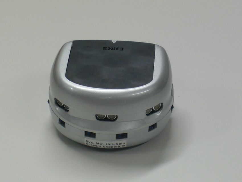
Figure 1: Khepera II robot extended for an outdoor test, implementing theoretical
assumptions about cricket phonotaxis. Described by Webb / Reeve / Horchler
2003 [25].

The choice of the Khepera II was at least partly motivated by the popularity
of the platform (see Schmidt 2005 [21]). At the time of the beginning of the
project, however, K-Team Corporation released a successor to the Khepera II,
the Khepera III robot. This new device offers greatly enhanced possibilities for
the development of control structures and interactive applications, but also con-
fronts the developer with a new set of challenges, e.g. dealing with the use of
embedded Linux operating systems, but partly also resulting from insufficient
documentation and the lack of example applications.

As reported elsewhere (Schmidt 2005 [21], 2007 [22]; Schmidt / Seifert 2006 [23]),
a technical goal of our project is to provide an interface for the Open Sound
Control (OSC) protocol to access the control of the Khepera III robot. The OSC
protocol was designed to connect sound programming applications via standard
internet connections providing a flexible framework to specify messages sent bet-
ween the applications (e.g. Wright / Freed / Momeni 2003 [29], Wright 2005 [28],
current state of the protocol specification [27, 26]). The protocol has been im-
plemented within popular sound programming environments such as Max/MSP,
Pure Data (Pd) and SuperCollider, but even in general purpose programming
languages such as Java or C++. Thus, an OSC interface could enable access to

                                        2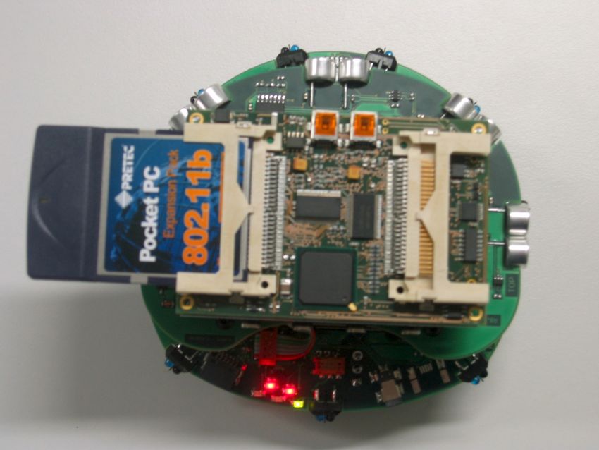
the Khepera III independent of the application / programming language used.
Of particular interest for the implementation and investigation of interaction
based on sound-related movements / gestures may be the possibility afforded by
an OSC interface to integrate work presented by Jensenius: tools are developed
for the analysis of (musical) gestures – to be run within the Max/MSP/Jitter
environment – along with the discussion of relevant features for the analysis
and appropriate formats for streaming related data (e.g. Jensenius / Godøy /
Wanderley 2005 [10], Jensenius 2006 [7], Jensenius et al. 2007a,b [8, 9]). 4
At the time of writing, the goal of providing an OSC interface has not been
achieved yet. A preliminary solution using a network connection via a Pd patch,
however, can be presented and will be described in some detail below. This de-
scription will include aspects of the robot’s control architecture, the knowledge
of which is a prerequisite for setting up an OSC interface. Mastery of these steps
should render the design of the OSC interface a technicality, albeit probably still
rather time consuming.
We will start with a superficial technical description of the Khepera III, next turn
to the Pd application for interacting with the robots and finally take an intense
look at the underlying (low level) control programs.

  4
      http://www.infomus.org/EywIndex.html

                                         3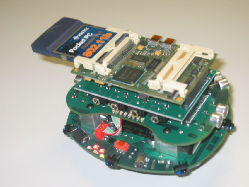
1 Technical Description of Khepera III
The Khepera III is a small, circular mobile robot running on two wheels and a
sliding support. The diameter is about 130 mm, the height about 70 mm and the
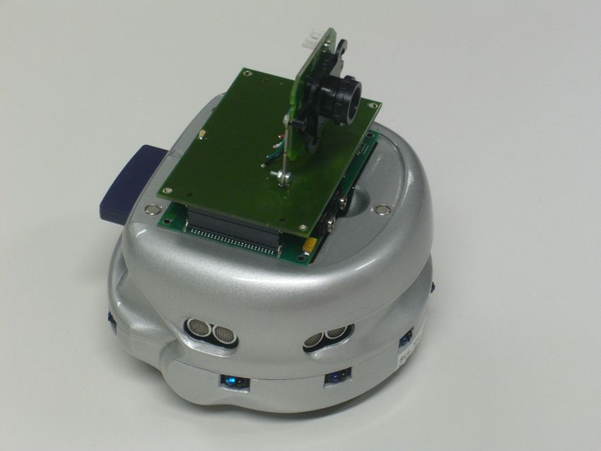
weight without extensions amounts to ca. 690 g5 . Different view of the Khepera
III are presented in figure 2, the top row showing a prototype and the bottom
row the current commercially available version.
In its basic configuration, the Khepera III is equipped with two motors with asso-
ciated controllers, a ring of 9 infrared (IR) sensors attached to the bottom layer of
the robot’s internal structure, another ring of ultrasonic (US) sensors attached to
the second layer and an additional pair of IR sensors pointing downward (called
ground sensors). Communication with and control of these devices is mediated
by a dsPIC 30F5011 microprocessor. (For a textbook description of hardware
devices for mobile robots see e.g. Jones / Flynn / Seiger 1999 [11] or Nehmzow
2000 [16].)
More specifically, each of the motors is equipped with an incremental shaft en-
coder producing 16 pulses per revolution of the motor axis; since the motor is
connected to the wheels with a 43.2:1 reduction (i.e. 43.2 motor axis revoluti-
on corresponding to 1 revolution of the wheel), one revolution of the wheel will
correspond to 691.2 pulses produced by the shaft encoder. Because 55 pulses are
stated to correspond to 10 mm of distance covered by the robot (Khepera III
User Manual [14], Section 3.2), the diameter of the wheels can be calculated to
be 40 mm.6
The incremental encoder together with a PIC 18F4431 microprocessor (technical
data in [15]) reading the encoder pulses and controlling the pulse width of a 20
MHz pulse, which provides the electrical power of the motor, allows for two dif-
ferent modes of motor control: control of position making use of the number of
pulses registered (which can be converted into distances according to the calcu-
lations indicated above) and control of speed measuring the number of pulses in
time; the maximum speed is specified as 1 m/s.7 For both control modes, different
options and values (including proportionality constants for PID controllers) can
be set. The motor controllers act as I2C slave devices (for a detailed description
of the I2C bus see [20]).
5
All technical details if not explicitly stated otherwise are taken from the Khepera III User
Manual (Lambercy / Bureau [14], the version referred to here is dated 2007-03-12) and the
specifications published on the website of K-Team Corporation, http://www.k-team.com. The
material referred to can be retrieved in the latest revision from this site.
6
691.2 pulses correspond to 2πr, therefore 691.2 2π = 110.01 pulses correspond to r. On the
other hand 110 pulses correspond to 20mm, therefore the radius r equals 20 mm and the
diameter will be 40 mm.
The value of 22 pulses per 1 mm robot movement given in the online specification does not
appear to be compatible with the User Manual / the actual size of the wheels.
7
resp. 0.5 m/s following the online specifications
4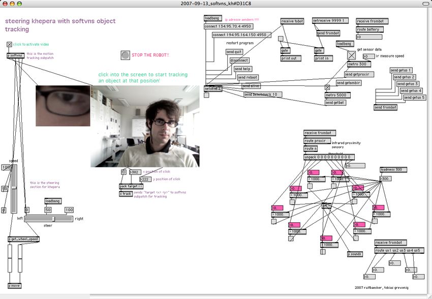
Figure 2: Khepera III mobile robot.
Top row: Prototype, still without chassis.
Bottom row: Left panel standard form; right panel with KoreSound card and
USB camera.

Even the IR sensors provide two modes of measurement: Every sensor consists
of one receiver for infrared radiation and one emitter. In the mode using only
the receiver part of the sensors, the intensity of infrared radiation present in the
robot’s environment will be measured. This mode, which is called ambient ir mea-
surement, may e.g. be used to implement heat following or avoiding behavior as
classically described by Braitenberg 1984 [1], Vehicles 2 – 4. In the mode referred
to as proximity ir measurement, the IR emitters are used to obtain a comparison
between ambient infrared radiation and radiation reflected from surfaces nearby.
More specifically, the value returned from the sensor is the difference in intensi-
ty measured between the conditions with IR emitter turned on and IR emitter
turned off. Thus, proximity IR measurement does not directly provide a measure
of distance to an object: For identical surface conditions, the sensor reading will
increase when the distance is diminished; for different surfaces, however, sensor
readings will differ according to the reflecting / absorbing properties of the sur-

                                         5
faces even if distance is kept constant. According to the online specification, the
measuring range for proximity IR measurement is up to 25 cm; the measurement
is mainly intended for the implementation of obstacle avoidance (Khepera III
User Manual, Section 3.3).
The 11 sensors are read consecutively, starting at the rear left and going clockwise
along the ring to the sensor pointing straight backwards, taking the right and left
ground sensors last; it is in this order in which the sensor readings are returned
as a list when the built-in commands for retrieval of sensor data are issued (see
below). The time to jump from one sensor to the next is specified as 3 ms, thus
each sensor is read every 33 ms. In its present state, the Khepera III User Manual
does not give any precise interpretation of the IR sensor values returned.8
Longer range distance measurements (20 cm to 4 m) are performed by the ultra-
sonic sensors. In the default operation mode of the Khepera III, only the sensor
pointing forward is active. Due to the low speed of sound (as compared to the
speed of light), ultrasonic measurement requires inherently longer time than IR
measurement: for a maximum distance of 4 m to an obstacle, i.e. a traveled di-
stance of 8 m for a reflected ultrasonic sound burst, and a speed of sound of 320
m/s, the required time for one measurement is at least 25 ms – thus, in situations
requiring rapid interaction, ultrasonic measurement shouldn’t be employed too
frequently.
In the basic configuration of the Khepera III, the dsPIC 30F5011 processor ope-
rates as an I2C master device controlling the motor controllers and reading the
sensors. To access the various control functions and to retrieve sensor data, a
communication protocol has been implemented consisting of single character com-
mands, which can be followed by additional parameters. Commands are entered
as capital letters producing an effect on the robot and evoking a response on the
command line. As a simple example, entering the command ‘A’ will result in the
robot entering the “Braitenberg mode,” which instantiates some form of wande-
ring behavior including obstacle avoidance – no detailed description is given in
the User Manual – and returning the small letter ‘a’ on the command line.
As another example, which will be taken up below, consider the command ‘N’:
entering ‘N’ will result in the retrieval of the current proximity measurements of
the IR sensors. The answer displayed on the command line consists of the small
letter ‘n’ followed by eleven numbers representing the sensor readings in the order
described above and another number specifying the relative time stamp, i.e. the
value of the “relative time counter” (User Manual, page 36) indicating the time
of measurement.
Further commands are used to configure the mode of operation of the Khepera III,
8
Even the format of the numbers returned is not specified coherently: according to Section
3.3, the values are 12 bit numbers (without type specification), in Appendix A describing the
built-in commands the values are defined as 10 bit numbers . . .
6to set various options for the motor controllers or the desired speed / position
values, or to retrieve other data from the robot (see Appendix A of the User
Manual for a complete list).
To access the command line e.g. via a serial connection, a terminal emulator
should be running on the host computer and be connected to a serial port, which
can be connected to the RS 232 connector of the KoreConnect adapter intended
for operation of the Khepera III in the basic configuration without a KoreBot
extension.
The major innovation introduced with the Khepera III robot is the possibility to
connect a KoreBot board via the KB-250 extension bus, i.e. by “stacking” the
KoreBot board on top of the robot.
The main component of the KoreBot board is an Intel PXA255 XScale pro-
cessor running at 400 MHz with 60 MB RAM and 32 MB flash memory. The
PXA255 processor was developed for “handheld computing applications” ([5],
page 1-1) supporting an ARM embedded Linux operating system (for technical
details concerning the processor see PXA255 User’s / Developer’s Manual [6, 5]).
In addition, the KoreBot board provides a PCMCIA slot to which in our case a
standard wireless network card is connected. In Figure 2, top row, the topmost
level of the robot is formed by another version of the KoreBot board carrying
two PCMCIA slots; in the actual version – Figure 2, bottom row – the layout has
been changed allowing to stack further extensions on top of the KoreBot board,
which is situated within the robot’s chassis.
When the KoreBot board is mounted on the Khepera III robot, the dsPIC micro-
controller running the communication protocol switches to the I2C slave mode.
As a consequence, the control commands described above can no longer be ente-
red directly. Instead, commands have to be transmitted to the dsPIC processor
via the I2C bus. For this purpose, a C library containing functions implementing
the low level communication with the I2C devices is provided by K-Team Cor-
poration. The latest version of this library is libkorebot-1.10; in the following, we
are referring to libkorebot-1.9.19 .
Access to the ARM Linux command line can again be established via a seri-
al connection as described above but now using the RS 232 connector of the
KoreConnect adapter intended for use with the KoreBot board. Alternatively,
standard (wireless) network connections can be used such as telnet / ssh resp.
ftp / sftp.
The first of the new challenges mentioned above that are posed by the Khepera
III platform more precisely concerns the setup of a cross compilation toolchain
for the ARM Linux system running on the KoreBot board, i.e. an environment
9
The libraries can be retrieved from the K-Team ftp server: http://ftp.k-team.com/
korebot/libkorebot/.
7that allows to compile executable programs (e.g. from C or C++ source code) for
the ARM Linux system on a different – e.g. Mac OS X or Windows – platform.
Here, we will refrain from further discussion of this topic, “simply” asserting that
we have successfully compiled the C code discussed below for the Khepera III
robot extended with a KoreBot board.
The other challenge, the still incomplete and at times – at least apparently –
inconsistent state of the Khepera III documentation has been illustrated in the
discussion.
Further extensions available for the Khepera III and displayed in Figure 2, lower
right panel, include the KoreSound card providing audio input and output and a
USB camera.
82 Pd Interaction with Khepera III
We will start our discussion of interaction with the Khepera III robot with the
description of a pure data (pd) application providing a “high level” interface.
The patch shown in Figure 3 was originally prepared by Tobias Grewenig and
Ralf Baecker within the research project mentioned above; some additions and
corrections were introduced by the present author.
In the figure, four regions enclosed by polygons are displayed. These regions
correspond roughly to different types of functionality:
1. In the upper right area, functions pertaining to network interaction are
collected;
2. the area on the left is related to movement control of the robot;
3. functions in the lower right area address the ultrasonic sensors and display
data obtained from US measurement;
4. the functions collected in the lower middle evaluate data retrieved from the
infrared sensors.
Network communication with the Khepera III is established using the Pd netsend
and netreceive objects10 . Here, they are used with a non-zero creation argument
(the argument following the function name in the corresponding object boxes)
specifying the network protocol to be used as the UDP (User Datagram Protocol)
protocol; a zero or missing creation argument would set the TCP/IP protocol.
The IP address and receiving port number of the robot need to be edited in
the message box containing the connect command. The robot’s receiving port
is defined in the control program running on the KoreBot board, the IP address
must of course conform to the momentary IP configuration of the KoreBot.
Data is sent to the robot in the form of messages consisting of sequences of
characters (including numerals), which by the control program are interpreted as
10
The shapes and basic functionality of the Pd boxes used in Figure 3 are indicated in the
following figure:
9III robot.
10
Bounded regions roughly correspond to network communication (upper right), movement
control (left), IR measurement (center), US measurement (lower right).
Calculation of actual speed values sent to motor controller is performed in the canvas
object ‘pd get wheel speed’.
Figure 3: Pd patch implementing the wireless communication with the Kheperanames and arguments of robot control commands: Whenever any of the message
boxes containing a message that starts with send is activated (by clicking or by
an activating impulse – bang – from another component of the patch), the part
of the message following send, e.g. quit or getambir is transmitted to the robot
by the netsend object.
Incoming data from the robot is received by the netreceive object. The first
creation argument of netreceive sets the port of the host computer listened to;
in the control program running on the KoreBot, this is defined as the sendport
number. In a setting involving more than one robot, different sendport numbers
are specified in the resp. control programs to keep apart data from the different
sources.
Within the patch, data received from the robot is distributed using the Pd internal
send and receive objects: data transmitted from the send frombotA object will
be processed by any receive frombotA object in any currently opened Pd patch.
Data to be processed is selected using the Pd route function; the need for the
consecutive route objects in the context of IR measurement will become clear in
the discussion of low level control below
The evaluation ultrasonic measurement in the application shown is restricted to
the display of sensor values; the geometrical arrangement of the number boxes in
the patch reflects the placement of the corresponding US sensors on the robot.
Even the number boxes displaying the reading of the IR sensors (red boxes in the
lower middle area) are arranged corresponding to the placement on the robot,
discarding the data retrieved from the ground sensors. The values in this patch
are used for two different purposes: whenever any sensor reading exceeds the value
of 300, an activating impulse is generated. On the one hand, this is sent to the pd
sounds canvas object triggering the playback of a short sound sample (“boing”;
the functions used are encapsulated within the canvas object). On the other
hand, the impulse is sent to the pd autopilot canvas object that implements
an automatic movement control of the robot including obstacle avoidance. When
the autopilot is turned on and receives an impulse resulting from an IR sensor
reading higher than 300 – indicating the presence of some object in the vicinity
of the robot – the robot’s direction of movement is inverted until new speed and
direction values are generated randomly.
When the autopilot is turned off, movement of the robot can be controlled in two
different ways using this patch: the (green) slider objects are used to generate
values for speed (vertical slider) and direction (horizontal slider) independently,
the grid object functions as a controller resembling a joystick. The numerical
values generated by the slider and grid objects range from 0 to 100; calculation
of the actual values sent to the robot is encapsulated in the pd get wheel speed
canvas object, in the pd move object the values are combined into messages with
the appropriate control command setmotspeed.
11Figure 4: Patches for control of the Khepera III via OSC
Top: separate patches for speed and direction control
Bottom: patch receiving control data
In addition to the patch discussed, a set of small Pd applications for movement
control of two Khepera III robots via OSC connections (shown in Figure 4) was
prepared. In the patches displayed in the top row, numbers in the range 0 to 100
generated by slider objects are combined into messages with keywords indicating
the intended use of the numbers; the keyword /steerA refers to direction control,
the keyword /speedA to speed control, and the capital letter ‘A’ included in both
keys indicates the robot addressed. Using the sendOSC object, the messages are
coded according to the OSC specification and sent to the IP address and port
defined in the connect ... message box. On the computer indicated by the
IP address, the messages can be received and decoded using the dumpOSC ...
listening to the port defined in the sending patches (see bottom row of Figure
4). Here, the message received is transmitted further within the Pd application
using the s rcvOSC object11 . A corresponding r rcvOSC object is included in the
control patch of Figure 3, again using the route function to select data for speed
and direction control according to the keywords /speedA and /steerA.
These patches were informally tested in a playful classroom situation, serving as
an example to illustrate possible applications of the OSC protocol. The “slider
patches” were running on five or six different laptop computers and there was a
host computer running control patches for both robots. Participants were given
11
‘s’ is used as an abbreviated form of ‘send’; likewise ‘r’ is used as a shorthand for ‘receive’.
12the task to collaborate in controlling the robots in order to push a small box in
a certain direction – collaboration of at least two “operators” is required to steer
one robot because only one slider can be operated on any computer at a time.
The task turned out to be tricky for the following reasons:
– since the robots look alike, the operators first need to find out which one
reacts to the objects they are manipulating – and keep track of “their”
robot once they found out,
– operators can not be certain whether the reaction observed was a result of
their action,
– coordination with the person manipulating the other control parameter of
the robot needs to be established,
– other persons might be interfering with one operator’s actions,
– technical problems include reaction times of the robots and delays in the
transmission of control commands.
It is intended to replace the sliders by other input devices such as sensors registe-
ring body movements or motion tracking applications as developed by Jensenius
(see above) / the EyesWeb system (Camurri et al. 2007 [3]). A first motion
tracking application based on the patch described has been implemented by Jo-
chen Arne Otto (see Section 2.1). More sophisticated robot behaviors will be
taken into account as well.
132.1 Motion Tracking Using SoftVNS
Movement control of the Khepera III robot by camera based motion tracking was
implmented in the patch shown on the next page.
The patch is based on a one-to-one port – with the exception of the grid object –
of the Pd patch of Figure 3 to the MaxMSP environment, also provided by Tobias
Grewening and Ralf Baecker. Motion tracking functionality has been incorporated
by use of the softVNS external objects for MaxMSP by David Rokeby12 .
Here, a region of the camera image shown on the right can be selected and
tracked by the video processing objects collected in the subpatch p softvns. x
and y positions of the tracked region are mapped to the sliders for direction and
speed control of the robot.
Motion tracking components of this patch were developed by Jochen Arne Otto.
Two problems were encountered with this approach:
1. Too fast movement of the selected region could lead to losing track.
2. In more advanced versions of this patch, repeatedly the connection between
robot and computer got lost. Reasons for this problem are not clear yet; first
ideas concern internal timing issues and the loss of data packages during
transmission due to the use of the UDP network protocol.
12
http://homepage.mac.com/davidrokeby/softVNS.html
14Figure 5: MaxMSP patch using softVNS externals for movement control of the
15 tracking
Khepera III robot by camera based motion3 The libkorebot C Programming Library
As repeatedly mentioned in the previous section for interaction with the Khepera
III robot using the Pd patches described, a control program is required running on
the KoreBot board that decodes the messages sent to the robot into appropriate
control commands and corresponding arguments and on the other hand encodes
the responses from the robot into messages that can be put to use within the Pd
application. The control program to be discussed is based on a test application
for the Khepera III provided by K-Team Corporation as part of the libkorebot
libraries; the C source code is contained in the file khepera3 test.c. Along with
the preparation of the Pd patch, this application was modified by Tobias Grewenig
and Ralf Baecker to incorporate functions for network interaction and coding /
decoding messages sent between computer and robot. Networking functionality
was established by importing source code for the Pd netsend object by Miller
Puckette. Some changes and additions had to be introduced by the present author:
Grewenig / Baecker started from the application as provided with the libkorebot-
1.8 distribution. Since the return values of some low level functions were changed
from pointer to integer type with the libkorebot-1.9.1 distribution, the functions
in our application had to be adapted. Even the syntax and return values of some
commands of the communication protocol running on the dsPIC 30F5011 seem to
have been changed so that the functions making use of these had to be revised,
too. A minor change concerns the definition of different sendport numbers for
different robots.
In the following, we will specifically discuss the command for retrieving an am-
bient IR measurement, which involves both receiving and sending data on the
side of the robot, in order to gain some insight into the control architecture im-
plemented in the libkorebot distribution. The complete listing of the code for
the control application can be retrieved from our website13 . We will only look
at functions specific to the Khepera III platform, i.e. details of setting up the
network connection will be left out.
13
http://www.uni-koeln.de/phil-fak/muwi/sm/research/k3/khepera.html, link to c
programs, file pdcontrol.c.
163.1 Decoding Messages: Command Table and Command
Parser
Messages sent to the robot via an existing network connection will be written
into a character array. This array will be parsed – by a function defined in the file
kb commandparser.c of the libkorebot distribution – for names and arguments
to be executed; the parsing function is invoked by the line
kb parse command( sbuf, cmds, NULL);
sbuf is the name of the buffer containing the data and cmds is the name of a
structure defining the available command names.
More specifically, the command table cmds maps arbitrary strings to a minimum
and a maximum number of arguments to be entered and the name of a function
to be called. The actual function call is issued by the command parser program.
The command table of our application is defined as follows:
/*---------------------------------------------------------------*/
/*! The command table contains:
* command name : min number of args : max number of args : the
* function to call
*/
static kb_command_t cmds[] = {
{ "quit" , 0 , 0 , quit } ,
{ "exit" , 0 , 0 , quit } ,
{ "bye" , 0 , 0 , quit } ,
{ "ciao_bella" , 0 , 0 , quit } ,
{ "setcfg" , 2 , 2 , configureOS },
{ "getrev" , 0 , 0 , revisionOS },
{ "getbat" , 0 , 0 , voltageBAT },
{ "rststamp" , 0 , 0 , tstampRST },
{ "getambir" , 0 , 0 , ambIR },
{ "getproxir" , 0 , 0 , proxIR },
{ "getus" , 1 , 1 , measureUS },
{ "setmotspeed" , 2 , 2 , motSpeed },
{ "setmotmove" , 2 , 2 , motMove },
{ "motstop" , 0 , 0 , motStop },
{ "help" , 0 , 0 , help } ,
{ "getallus" , 0 , 1 , getallUS },
{ "benchmark" , 1 , 1 , getBenchmark },
{ "reboot" , 0 , 0 , doReboot },
{ "alive" , 0 , 1 , alive },
{ NULL , 0 , 0 , NULL }
};
17As can be seen from the first four entries, any number of strings can be associated
with one function name, here: quit. As also illustrated, command names can be
arbitrary but should be chosen so as to indicate the function performed.
The commands defined in our example may pertain to (list not exhaustive):
– the operating system of the dsPIC processor: setcfg can be used to confi-
gure the mode of operation, e.g. the number of US sensors active; getrev
retrieves the current revision of the operating system,
– further information about the current state of the robot: getbat in the
revision addressed here retrieves the momentary battery voltage; in a more
recent version, some more information including the battery temperature
can be obtained,
– retrieval of sensor data: getambir and getproxir retrieve ambient resp.
proximity IR measurements, getus retrieves the ultrasonic measurement of
the sensor whose number is entered as argument, getusall reads all US
sensors,
– setting of certain control values: for example, setmotspeed sets the desired
speed values for the motors thus requiring two arguments; in a similar way
setmotmove sets the desired position values,
– as an exception in this list, the command reboot leads to the restart of the
ARM Linux operating system of the KoreBot board.
The commands possibly included in messages sent by the Pd patch are: getproxir,
getambir, getbat, getus 1...5, quit, help, and setmotspeed – the last is used
within the object pd move of the patch.
We will concentrate on the command getproxir. As can be seen in the command
table, no arguments are required or allowed. Upon finding the string getproxir
in the input array without arguments, the command parser will call the function
proxIR defined as shown below within the control program.
183.2 Retrieving IR Data: getproxir → proxIR
The function proxIR, which is called when a message containing the command
getproxir is received, is defined by the following code fragment:
/*--------------------------------------------------------------------*/
/*! proxIR retrieves proximity ir measure using kb_khepera3.c library.
*/
int proxIR( int argc, char * argv[], void * data)
{
char irdata[512];
char Buffer[MAXBUFFERSIZE];
if(kh3_proximity_ir((char *)Buffer, dsPic)) {
sprintf(irdata,"proxir %c %4.4u %4.4u %4.4u %4.4u %4.4u %4.4u %4.4u %
4.4u %4.4u %lu\n",
Buffer[0], (Buffer[1] | Buffer[2]encodes the small letter ‘n’ is processed independently. The following elements of Buffer are combined in eleven pairs, each pair encoding the reading of an IR sensor in two bytes. The bit shifting operation performed on the second element of each pair14 points at the fact that numbers are encoded in the little endian format. The inclusion of the element Buffer[0] necessitates the presence of the route n object in the part of the Pd patch evaluating IR sensor data. 14
3.3    Integrating the Communication Protocol:
       kh3 proximity ir
Turning to the function kh3 proximity ir will illustrate the way commands of
the communication protocol are accessed by control programs running on the
KoreBot board. The definition of this function including comments is presented
in the following code fragment:
/*!
 * kh3_proximity_ir retrieves an instant IR measure.
 * \param outbuf is a buffer where the data will be stored on.
 * \param hDev is a handle to an openned knet socket (Khepera3:dsPic).
 * \return NULL or a pointer to the IR measure
 */
int kh3_proximity_ir(char *outbuf, knet_dev_t *hDev){

  int rc , i;

  /* Frame format : { Size, Command, Terminator }
   * where the command can be more than 1 byte */
  char cmd[3] = { 2, ’N’, 0};

  if(hDev) {
  kh3_sendcommand( hDev , cmd );
   /* delay to ensure the correct reading of KNET_INT0 pin */
usleep(K3_CMD_DELAY);
while(!kb_gpio_get(KNET_INT0));

rc = kh3_getcommand( hDev, outbuf );
return rc;
          }
   return 0;
}
As evident from the specifier preceding the function name, the return value of the
function is of type integer – but according to the last line of the initial comment
it should be a NULL pointer or a pointer to the array holding sensor data. This
is another example of documentation problems which led to misunderstandings
and delay in setting up the Pd interaction.
As discussed in the previous section, the two arguments of the function are poin-
ters to an array holding data and to the device data will be retrieved from, the
dsPIC processor.
In the body of the function, a command frame cmd is defined in the form of a
character array. The array holds as its first element the number of bytes following

                                        21
this element. The second element is a character specifying a command of the
communication protocol, here the capital letter N, if required / admissible followed
by any arguments of the command – none in our case. The last element of the
command frame is 0, used as a terminating symbol.
The function kh3 proximity ir makes use of two other functions, kh3 getcommand
and kh3|sendcommand, which, too, are defined within the file kb khepera3.c. As
the names indicate, the first of these is used to pass the command frame to the
dsPIC processor, the second retrieves the answer produced by the dsPIC and
writes it to the array Buffer referenced by the pointer outbuf.
Between the passing and retrieving commands, a delay is inserted consisting of
a fixed amount of time defined by the constant K3 CMD DELAY and a variable
part determined by the condition of a while loop. In the file kb khepera3.h, the
constant K3 CMD DELAY is set to 300 µs, the while loop waits for a certain pin to
signal readiness.
223.4 Interacting with the dsPIC:
kh3 sendcommand and kh3 getcommand
The functions kh3 sendcommand and kh3 getcommand are “as far down” as we will
have to go. All sensor related functions defined in the control program eventually
make use of these functions, because the sensors are controlled by the dsPIC
processor.
Although appropriate commands for motor control are available in the commu-
nication protocol, these can not be used in the manner described here: Since the
dsPIC processor operates in the I2C slave mode in connection with the KoreBot
board, no commands will be issued to the I2C devices controlling the motors, the
PIC 18F4431 processors. Instead, special functions defined in the file kmot.c of
the libkorebot distribution have to be employed.
The code defining kh3 sendcommand and kh3 getcommand is included as an illus-
tration in the code fragments at the end of this section. The first argument of
kh3 sendcommand is a pointer to the dsPIC device, the second argument points
to the command frame defined within kh3 proximity ir. The pointer to the
array Buffer defined in the function proxIR is passed as second argument to
kh3 getcommand eventually writing data into Buffer, which then can be sent to
the host computer as described above.
These remarks may suffice as an overview to give an impression how interaction
with the Khepera III can be implemented. For actual programming work – e.g.
preparing an OSC interface as proposed above – of course more detailed work
will be required, but the general framework should be clear.
23Code Fragment: kh3 sendcommand
/*!
* kh3_sendcommand sets a command frame to a given khepera3 device.
*
* Normally and end user doesn’t want to use these function as they are
* assumed as "low level functions".
*
* \param hDev is a handle to an opened knet socket (Khepera3:dsPic).
* \param in is a pointer to a buffer where the command frame to be sent
* is stored on.
*
* \return A value:
* - =0 on success (returns should be the size of frame)
*
* \remark This function requires that kb_kh3_init has been called
*/
int kh3_sendcommand( knet_dev_t *hDev, unsigned char *in )
{
char sizeMsg;
/* first byte in the frame is the complete frame size */
sizeMsg = in[0];
if( knet_llwrite( hDev, in, sizeMsg) == sizeMsg)
return sizeMsg;
else
{
KB_ERROR("knet_sendCommand", KB_ERROR_KH3FRMSNDERR);
return KH3_ERROR_FRMSND;
}
}
24Code Fragment: kh3 getcommand
/*!
* kh3_getcommand gets a command frame from a given khepera3 device.
*
* Function flow:
* - a) : retrieve the first byte which is the frame size from the device
* - b) : retrieve the required bytes
*
* Normally an end user don’t want to use these function as they are
* assumed as "low level functions".
*
* \param hDev is a handle to an openned knet socket (Khepera3:dsPic).
* \param out is a pointer to a buffer where the command frame
* will be stored on.
*
* \return A value:
* - =0 on success (returns should be the size of frame)
*
* \remark This function requires that kb_kh3_init has been called
*/
int kh3_getcommand( knet_dev_t *hDev, unsigned char *out )
{
char sizeMsg;
int rc;
if( knet_llread( hDev, &sizeMsg, 1 ) == 1 )
{
rc = knet_llread( hDev, out, sizeMsg );
if(rc == sizeMsg)
return rc;
else
{
KB_ERROR("knet_getCommand", KB_ERROR_KH3FRMSZERR, rc, sizeMsg);
return KH3_ERROR_FRMSZ;
}
}
else
{
KB_ERROR("knet_getCommand", KB_ERROR_KH3SZFMTERR);
return KH3_ERROR_SZFMT;
}
}
254 C Programming – Initial Steps
4.1 Short List of C Programs
1. k3 circle test.c: application that lets K3 move on a circle with a given
radius and speed for an amount of time to be entered in milliseconds. Ente-
ring 0 will terminate the program. Default value for speed: 20. Default value
for radius: 20 cm. Alternative values for speed and radius can be specified
as command line parameters:
./k3 circle test radius motspeed
i.e. the first parameter will be interpreted as radius, the second parameter
– if present – as speed value.
A simple form of obstacle avoidance for K3 is implemented in k3 move dur():
if any of the ir sensors 3, 4, 5, or 6 returns a proximity value exceeding the
value defined in macro K3 IR THRESHOLD, K3 moves backward 300 ms, turns
on the spot away from the obstacle, and resumes the original motor speed
values.
2. k3 neural 2.c: perceptron included in control program, network configura-
tion etc. provided via commnd line interaction, learning of patterns entered
via command line and sensor interaction.
3. pdcontrol.c: control program for Pd interaction with the Khepera3 robots
used within the project. Different robots, denoted by capital letters A and
B, are distunguished by the port numbers used.
In addition to these programs, the followoing header files will be needed:
1. k3 definitions.h
2. pdsend.h
3. percept2.h
C programs can be retrieved from http://www.uni-koeln.de/phil-fak/muwi/
sm/research/k3/khepera.html, following the link C-Programme.
4.2 Driving Circles
The movement patterns developed by Burger (2007 [2]) for the LEGO NXT
robot M[ε]X contained as one major component circular segments. Originally, the
patterns were implemented in the graphical programming environment NXT-G
provided by LEGO.
26In preparation for an observational experiment performed at the International
Summer School in Systematic Musicology (ISSSM) 200715 in Ghent, the programs
were re-written in the textual programming language Not eXactly C (NXC)1617 .
One of the questions addressed in this experiment concerned the impact of the
robot’s shape on the outcome of observational data. It appears meaningful to re-
write the programs once again in the language C for an implementation for the
Khepera III robot, in order to include the Khepera III in an extended comparison.
As a building block we will present here a short program implementing movement
of the Khepera III on a circle with a given radius. Since the direction of the robot’s
movement is determined by the speed settings of the two motor controllers, it is
necessary to provide a formula calculating the appropriate relationship between
motor speeds for a desired circle radius. The formula is derived from simple
geometrical considerations, assuming ideal contact between robot wheels and
floor, as follows (for an illustration see Figure 6):
v1: speed of
inner wheel
radius of circle wheel distance:
13 cm
Figure 6: Driving a circle with a Khepera III robot: The radius of the circle is
measured as the distance from the center to the inner wheel, and the speed v1 is
measured for this wheel.
The desired radius r1 of the circle is specified as the distance from the center of
the circle to the wheel closer to the center (henceforth inner wheel). The distance
r2 to the farther wheel will then be
r2 = r1 + d,
15
http://www.ipem.ugent.be/ISSSM2007/ISSSM2007.html
16
http://bricxcc.sourceforge.net/nbc/
17
NXC programming was done jointly using a collaborative text editing tool by B. Buch, B.
Burger, S. Chang, J. Kim, J.A. Otto, L. Schmidt, and U. Seifert.
27where d is the distance between the two robot wheels, which amounts to d = 13
cm.
For the robot to stay on the circular track, both wheels will have to move around
the center of the circle with a common angular velocity ω. Therefore, the speeds
v1 of the inner wheel and v2 of the outer wheel will be
v1 = ωr1
v2 = ωr2
Calculating the ratio of the speeds will cancel out the common factor ω:
v2 r2 r1 + d d
= = =1+ .
v1 r1 r1 r1
Thus, specifying the inner radius r1 of the circle and the speed v1 of the inner
wheel, the appropriate speed v2 for the outer wheel to keep the robot on the
desired circular course will be
d
v2 = v1 (1 + ).
r1
Depending on the assignment of v1 and v2 to the two motors, the robot will
perform a left or right circular movement with the inner radius r1 .
With the remarks on Khepera III C programming given above and the comments
included, the c code available from http://www.uni-koeln.de/phil-fak/muwi/
sm/research/k3/khepera.html should be readable.
References
[1] Braitenberg, Valentino (1984): Vehicles. Experiments in Synthetic Psycho-
logy. Cambridge, MA: MIT Press.
[2] Burger, Birgitta (2007): Communication of Musical Expression from Mobi-
le Robots to Humans. Recognition of Music Emotions by Means of Robot
Gestures. Master’s thesis. KTH Stockholm.
[3] Camurri, Antonio, Coletta, Paolo, Varni, Giovanna & Ghisio, Simone (2007):
Developing multimodal interactive systems with EyesWeb XMI. In: Pro-
ceedings of the 2007 Conference on New Interfaces for Musical Expression
(NIME07), New York, NY, USA. 305 – 308.
[4] Ichbiah, Daniel (2005): Robots. From Science Fiction to Technological Re-
volution. New York: Harry N. Adams.
28[5] Intel (2003): Intel PXA255 Processor. Developer’s Manual. Tech. rep.. Intel.
[6] Intel (2003): Intel PXA255 Processor. User’s Manual. Tech. rep.. Intel.
[7] Jensenius, Alexander Refsum (2006): Using Motiongrams in the Study of
Musical Gestures. In: Proceedings of the 2006 International Computer Music
Conference. New Orleans.
[8] Jensenius, Alexander Refsum, Camurri, Antonio, Castagné, Nicolas, Mae-
stre, Esteban, Malloch, Joseph, McGilvray, Douglas, Schwarz, Diemo &
Wright, Matthew (2007 a): Panel: The Need of Formats for Streaming and
Storing Music-Related Movement and Gesture Data. In: Proceedings of the
2007 International Computer Music Conference. Copenhagen.
[9] Jensenius, Alexander Refsum, Castagné, Nicolas, Camurri, Antonio, Mae-
stre, Esteban, Malloch, Joseph & McGilvray, Douglas (2007 b): A Summary
of Formats for Streaming and Storing Music-Related Movement and Ge-
sture Data. In: Proceedings of the 4th International Conference on Enactive
Interfaces. Grenoble.
[10] Jensenius, Alexander Refsum, Godøy, Rolf-Inge & Wanderley, Marce-
lo M. (2005): Developing Tools for Studying Musical Gestures within the
Max/MSP/Jitter Environment. In: Proceedings of the International Music
Computer Conference. Barcelona. 282 – 285.
[11] Jones, Joseph L., Flynn, Anita M. & Seiger, Bruce A. (1999): Mobile Robots.
Inspiration to Implementation, Second Edition. Natick, MA: A K Peters.
[12] Köhler, Achim (2007): Der C/C++ Projektbegleiter. Heidelberg:
dpunkt.verlag.
[13] Krüger, Guido (2007): C-Programmierung. Bonn et al.: Addison Wesley.
[14] Lambercy, Fredric & Bureau, Pierre (2007): Khepera III User Manual. Tech.
rep.. K-Team Corporation. Yverdon-les-bains.
www.k-team.com
[15] Microchip (2003): PIC18F2331/2431/4331/4431 Data Sheet. 28/40/44-Pin
Enhanced Flash Microcontrollers with nano Watt Technology, High Perfor-
mance PWM and A/D. Tech. rep.. Microchip Technology Incorporated.
[16] Nehmzow, Ulrich (2000): Mobile Robotics: A Practical Introduction. Lon-
don: Springer.
[17] Nichols, Bradford, Buttlar, Dick & Proulx Farrell, Jacqueline (1996):
Pthreads Programming. Beijing et al.: O’Reilly.
29[18] Nolfi, Stefano & Floreano, Stefano (2000): Evolutionary Robotics. The Bio-
logy, Intelligence, and Technology of Self-Organizing Machines. Cambridge,
MA: MIT Press.
[19] Pfeifer, Rolf & Scheier, Christian (1999): Understanding Intelligence. Cam-
bridge, MA: MIT Press.
[20] Philips Semiconductors (2000): The I2 C-Bus Specification Version 2.1. Tech.
rep.
[21] Schmidt, Lüder (2005): Towards an “Embodied Cognitive Science of Mu-
sic”: Incorporating Mobile Autonomous Robots Into Musical Interaction.
In: APSCOM05. Seoul.
[22] Schmidt, Lüder (2007): Embodied Cognitive Science as a Paradigm for Mu-
sic Research. In: Lischka, Christoph & Sick, Andrea (eds.): Machines as
Agency. Artistic Perspectives. Bielefeld: transcript Verlag. University of the
Arts Bremen Press Series 04. 48 – 62.
[23] Schmidt, Lüder & Seifert, Uwe (2006): Körperlichkeit und Musik. In: Neue
Zeitschrift für Musik (4): 44 – 45.
[24] Tanenbaum, Andrew S. (2009): Modern Operating Systems. Pearson Pren-
tice Hall.
[25] Webb, Barbara, Reeve, Richard, Horchler, Andrew & Quinn, Roger (2003):
Testing a model of cricket phonotaxis on an outdoor robotic platform. In:
Proceedings of TIMR03.
[26] Wright, Matthew. The Open Sound Control Specification.
http://opensoundcontrol.org/spec-1 0
[27] Wright, Matthew. OpenSound Control Specification.
http://www.cnmat.berkeley.edu/OpenSoundControl/OSC-spec.html
[28] Wright, Matthew (2005): Open Sound Control: an enabling technology for
musical networking. In: Organised Sound 10(3): 193 – 200.
[29] Wright, Matthew, Freed, Adrian & Momeni, Ali (2003): OpenSound Con-
trol: State of the Art 2003. In: Proceeding of the 2003 Conference on New
Interfaces for Musical Expression (NIME-03). Montreal.
30You can also read