Lightweight Structures and the Geometric Equilibrium in Dragonfly Wings - Polyhedral ...
←
→
Page content transcription
If your browser does not render page correctly, please read the page content below
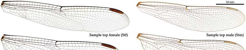
Proceedings of the IASS Annual Symposium 2020/21 and
 the 7th International Conference on Spatial Structures
 Inspiring the Next Generation
 23 – 27 August 2021, Guilford, UK
 S.A. Behnejad, G.A.R. Parke and O.A. Samavati (eds.)

 Lightweight Structures and the Geometric Equilibrium in
 Dragonfly Wings
 Hao ZHENG*,a, Marton HABLICSEKb, Masoud AKBARZADEHa

 *,a Polyhedral Structures Laboratory, Stuart Weitzman School of Design, University of Pennsylvania
 Pennovation Center, 3401 Grays Ferry Ave. Philadelphia, PA, 19146
 zhhao@design.upenn.edu
 b
 Mathematical Institute, Leiden University

Abstract
This research investigates the use of graphic statics in analyzing the structural geometry of a natural
phenomenon to understand its performance and its relevant design parameters. Nature has always been
the source of inspiration for designers, engineers, and scientists. Structural systems in nature are
constantly evolving to optimize themselves with their boundary conditions. This optimization follows
certain design rules that are quite challenging for a human to formulate or even comprehend. A dragonfly
wing is an instance of a high-performance, lightweight structure that has intrigued many researchers to
investigate its geometry and its performance as one of the most light-weight structures designed by
nature. There are extensive geometrical and analytical studies on the pattern of the wing, but the
underlying design logic is not clear. The geometry of the internal members of the dragonfly wings
mainly consists of convex cell which may represent a compression-only network on a 2D plane.
However, this property has not been geometrically analyzed from this perspective to confirm the
hypothesis. In this research, we use the methods of 2D graphic statics to construct the force diagram
from the given structural geometry of the wing. We use algebraic and iterative methods to report the
topological and geometric properties of the form and force diagrams such as the degrees of
indeterminacies of the network. For sample wings, we separate the internal and the boundary edges,
construct the force diagram, and finally reconstruct the structural forms. Comparing the magnitude of
the forces of the reconstructed network with the actual structure of the wing using the edge lengths of
the force diagram will shed light on the performance of the structure. Multiple analytical studies will be
provided to compare the results in both synthetic and natural networks and drive solid conclusions. The
success in predicting the force flow in the natural structural pattern using graphic statics will expand the
use of these powerful methods in reproducing the similar geometry of the natural structural system for
the use in many engineering and scientific problems. It will also ultimately help us understand the design
parameters and boundary conditions for which nature produces its master-pieces.
Keywords: graphic statics, form and force diagrams, natural structures.

1. Introduction

1.1. Previous Research on Dragonfly Wings
Nature has always been the source of inspiration for designers, engineers, and scientists. Among a
variety of natural structures, a dragonfly wing is an instance of a high-performance, lightweight structure
that has intrigued many researchers to investigate its geometry and its performance to be used in bio-
inspired design. The previous research related to the dragonfly wings falls into three main categories --
the description, the measurement, and the design.

Copyright © 2021 by the author(s) as listed above. Published in the Proceedings of the IASS Annual Symposium
2020/21 and the 7th International Conference on Spatial Structures, with permission.
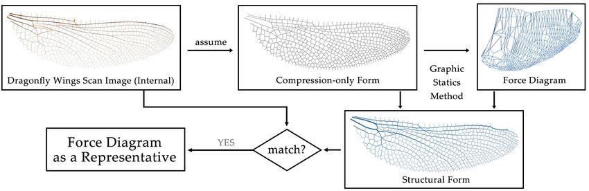
Proceedings of the IASS Annual Symposium 2020/21 and the 7th International Conference on Spatial Structures
 Inspiring the Next Generation

For description, researchers use high-tech tools to observe the dragonfly wings and summarize the
properties (usually morphology or pattern). Related research includes: 1) the nano-scale observation of
the wings, for example, the description of the nanomechanical behavior of the dragonfly wings [1], and
the finite element analysis of the structure and nano-mechanical properties of dragonfly wings [2]; 2)
the detail modelling and scanning of the joints, for example, the effect of the resilin-containing vein
joints on the stress distribution within the dragonfly wings [3], and three-dimensional finite-element
models of vein joints [4]; and 3) the general description of the morphology information, for example,
the insect wing mechanical design by comparing different insect wings including dragonfly wings [5],
the modeling and fabrication of the dragonfly wings patterns with the morphology analysis [6], the
dynamic deformation of the insect wings [7], and the morphometric measurements of scanned images
of dragonfly wings [8].
The other aspect focuses on the measurement and assessment of the dragonfly wings under certain
conditions. It includes: 1) aerodynamic performance measurement, for example, the aerodynamic data
collecting and presenting through wind-tunnel test [9], the effectiveness and efficiency of two pairs of
wings when flying [10], and the aerodynamic flow visualization when flying [11]; and 2) the other
functional performance, for example, the measuring the natural frequencies and mode shapes of
dragonfly wings [12], the superhydrophobicity and self-cleaning properties of the dragonfly wings in
nano scale [13], the functional characteristics of the dragonfly wings [14], and the initiation and
progression of wing damage [15].
The last aspect applies the design ideas inspired from the dragonfly wings, for example the design of
new materials and new structures. Related research includes: 1) the design of flight vehicle with flapping
wings inspired from the dragonfly wings [16], and 2) the exploration of the dragonfly wings in nanoscale
and the design of the nano-pattern of medical implant material inspired by the dragonfly wings [17].

1.2. Problem Statement and Objectives
In the previous research, the logic follows three steps: 1) measuring the dragonfly wings in different
scales; 2) testing the performance of the dragonfly wings under different conditions; 3) mimicking the
dragonfly wings for design solutions in similar environments. However, there is an obvious missing
logic between steps 2 and 3. Previous research only describes the property and the functions of dragonfly
wings. The intrinsic logic and the explanation, for example, why nature designs dragonfly wings in such
a way, are not provided. In addition, in the design-related research, the patterns of the dragonfly wings
are directly used as the design cases, without meeting the specific requirements, for example the
boundary conditions. Thus, the application of the dragonfly-wing-inspired design remains superficial at
mimicry level.
Based on the above analysis, we propose the following hypothesis: the geometry of the internal members
of the dragonfly wings mainly consists of convex cells, which may represent a compression-only
network [18, 19] on a 2D plane. This property motivates us to analyze the dragonfly wings (Figure 1)
from the perspective of axial loading. Therefore, this research aims at the investigation of the use of
geometric-based structural design method (graphic statics [20, 21, 22, 23, 24, 25, 26, 27, 28, 29]) in
analyzing the structural geometry of natural phenomenon to understand the internal flow of force and
their relevant design parameters, thus finally proving that this geometric-based structural design method
can be used to as a form finding tool for the design of similar structures.

2. Methodology

2.1. Graphic Statics Method
Graphic statics is a geometry-based method, where the equilibrium of force is shown by geometric
diagrams. In 2D graphic statics, the force diagram shows the force magnitude of the corresponding form
diagram. The length of each edge in the force diagram represents the force magnitude of the

 2
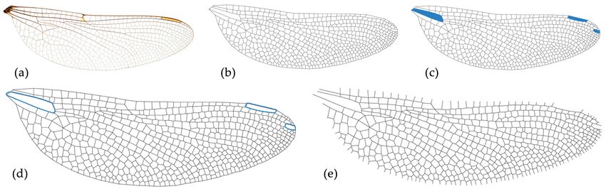
Proceedings of the IASS Annual Symposium 2020/21 and the 7th International Conference on Spatial Structures
 Inspiring the Next Generation

 Figure 1: Dragonfly wing samples and their patterns [30].

corresponding edge in the form diagram. Figure 2a shows a structural network and its force diagram.
The geometric transformation between the force diagram and the form diagram can be achieved using
graphic statics method. Figure 2b shows a 3D network and its projection and reciprocal diagram.
According to the force magnitude, the structural thickness of the form can be predicted.

Figure 2: Thrust Network Analysis: (a) two-dimensional equilibrium: a structural network and its force diagram;
 and (b) three-dimensional equilibrium: a 3D structural network and its projection and reciprocal diagram [31].

In the case of the dragonfly wing, its 2D pattern can be regarded as a structural form (Figure 3a), which
contains a group of closed polygons and each edge of the polygons has a unique structural thickness.
The simplified version of the dragonfly wing (Figure 3b) contains only the geometric information, it is
a representative form diagram of the dragonfly wing. Using graphic statics method, its corresponding
force diagram (Figure 3c) can be generated. Thus, by mapping the force magnitude to the structural
thickness, the corresponding structural form can be re-generated. The goal of this research is to compare
our generated wings with the real wings, and show whether the force distribution in the real wing follows
the rules of graphic statics. Therefore, the force diagram can explain the intrinsic logic of the design of
the dragonfly wing by nature.

2.2. Compression-only Network
To better use graphic statics to extract the force diagram, we assume the entire dragonfly wing as a self-
stressed system, in which the internal members bear axial compression forces, while the boundary
members and the membrane (abstractly rebuilt as triangulated members) together bear tension forces as
a constraint (Figure 4). Therefore, the internal structure represents a compression-only form, and the
rest represents a tension-only structure. By the following experiments, we will show why this
assumption is correct and how it benefits to the structural analysis.
Since we do not have a clear understanding of the external force of the dragonfly wing, we first exclude
the boundary edges of the dragonfly wing and focus on the internal network of the edges. Figure 5 shows
the process of the data preparation. The original dragonfly wing image (Figure 5a) is transformed into

 3
Proceedings of the IASS Annual Symposium 2020/21 and the 7th International Conference on Spatial Structures
 Inspiring the Next Generation

 Figure 3: The force and form of the internal structure of the dragonfly wings: (a) the actual form of the entire
 wing; (b) form diagram containing vertices (v), edges (e), and faces (f); (c) force diagram containing vertices
 (v†), edges (e†)), and faces (f†); and (d) the topological relationship between the elements.

Figure 4: The loading scenario of the dragonfly wing: entire wing as a self-stressed system, internal members as
 a compression-only form, boundary members and the membrane as a tension-only form.

the vector-based geometry with convex and non-convex polygons (Figure 5b) using image processing
techniques. The non-convex polygons (Figure 5c) are slightly adjusted to make convex polygons (Figure
5d). This allows the graphic statics method to work on the compression-only network. By removing the
boundary edges, the internal form (Figure 5e) is generated.

 Figure 5: Data preparation: (a) original dragonfly wing image; (b) vectorized form; (c) modifying non-convex
 cells (3 out of 573 (0.52%) cells); (d) modified convex form; and (e) internal form.

 4
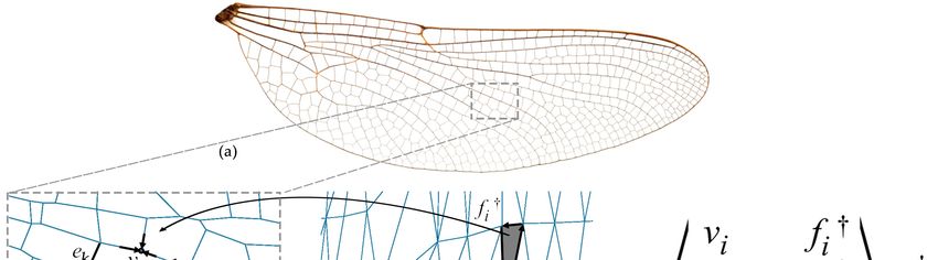
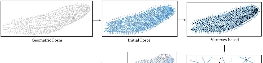
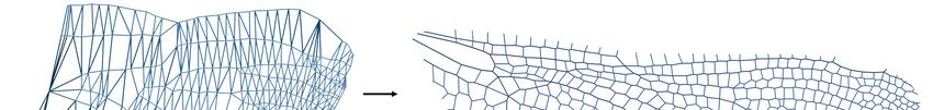
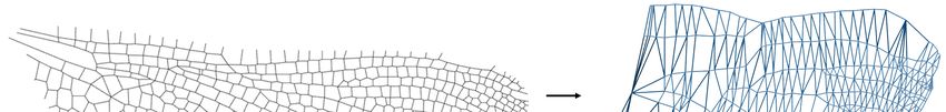
Proceedings of the IASS Annual Symposium 2020/21 and the 7th International Conference on Spatial Structures
 Inspiring the Next Generation

2.3. Algebraic Solution
The next step is to generate the force diagram based on the internal form diagram. In 2D graphic statics,
each edge in the force diagram is perpendicular to the corresponding edge in the form diagram. Figure
6 a shows a form diagram, which contains six internal edges and six external edges. In Figure 6b, the
proposed edges are presented as the dark blue lines, which are perpendicular to the edges in Figure 6a.
Therefore, each vertex (vi) in the form diagram has a dual polygon (fi†) in the force diagram. For each
polygon (fi†), a group of equations can be derived based on its edges (ei†) (Figure 6c).

 Figure 6: Algebraic solution: building equations.

Indeed, since the face fi† is a closed polygon, the sum of its edge vectors ej† should be zero. Hence, we
obtain a vector equation

 u 0

where the sum runs over the edges ej† of the face fi†, uj† denotes the unit edge vector of the edge ej†,
and the qj are the variables representing the lengths of the edges ej†. Writing these equations around
every face fi† provides a linear equation system for the edge length vector q which can be described by
a [2v * e] matrix, called the equilibrium matrix
 Aq 0
If the equilibrium matrix A is of full rank (or the Geometric Degrees of Freedom (GDOF) is zero), then
the only solution is the zero vector. In this case, the force diagram collapses to a point.

2.4. Iterative Solution
However, after experiments, we found that most of the dragonfly wings in our dataset have a GDOF of
0, which means there are no accurate solutions for most of the cases. Thus, the algebraic solution is not
stably applicable in all the cases of the dragonfly wings.
Therefore, we present an iterative method of PolyFrame [32, 33] that can generate the geometries of the
force diagram with a deviation (user-defined tolerance). The algorithm starts from constructing the
graph of the force diagram with incorrect edge lengths. Each polygon (fi) in the form (Figure 7a) is
transformed into a vertex (vi†) in the force (Figure 7b). Then the iterative method is applied to optimize
the position of each vertex (vi†) to make the corresponding edges perpendicular (Figure 7c). We also
define the difference between the vertical angle (90º) and the angle of the two corresponding edges (α)
as the deviation (δ). The optimization process works by a loop to minimize the value of δ (Figure 8).
With this geometric method, we can generate an approximate solution of the force diagram.

 5
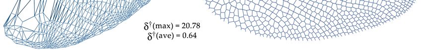
Proceedings of the IASS Annual Symposium 2020/21 and the 7th International Conference on Spatial Structures
 Inspiring the Next Generation

 Figure 7: Geometric solution: iterative method to update the positions of vertices.

 Figure 8: Flow chart of geometric method.

3. Results

3.1. Internal Form and Force
Using graphic statics method, Figure 9 shows the force diagram generated from the form diagram of the
dragonfly wing (form-to-force), and Figure 10 shows the generation of the form diagram from the
generated force diagram (force-to-form). The maximum deviations for the two processes are 46.64º and
20.78º, while the average deviations for the two processes are 2.64º and 0.64º. Therefore, the geometric
method successfully transforms the force diagram and the form diagram with small values of average
deviations. Figure 11 shows the distribution of the deviation of the form-to-force and the force-to-form
generation. Most of the members have a deviation smaller than 1º, and there are decreasing numbers of
members as the deviation increases. Only a few members have a deviation larger than 20º in the form-
to-force process and 10º in the force-to-form process. Therefore, most of the members in the force
diagram are accurately generated according to the corresponding form diagram, with the meaning of the
internal force magnitude.

3.2. The Thickness of the Dragonfly Wings Members
With the force diagram, the internal force for each form member can be obtained, thus the structural
thickness can be inferred, which is proportional to the force magnitude. We first measure the thickness
of the real wing in pixel, the minimum and maximum widths are approximately 6 pixels and 60 pixels.
We found that the ratio of the minimum and maximum force magnitude is also approximately 1:10, thus
we remap the force magnitude into the range of 3 to 30, and generate the structural pipes with the radius
of the remapped values. Therefore, the predicted internal structure (Figure 12a) is generated. Figure 12
shows the comparison of the generated internal structure and the real internal wing.

 6

Proceedings of the IASS Annual Symposium 2020/21 and the 7th International Conference on Spatial Structures
 Inspiring the Next Generation

Figure 9: The maximum and average form-to-force deviations in degrees (δ) in the generation of force from the
 form.

 Figure 10: The maximum and average force-to-form deviations in degrees (δ†) in the generation of form from
 the force.

Figure 11: The distribution of two deviations. δ: form-to-force deviation in degrees. δ†: force-to-form deviation
 in degrees. n: number of members.

 Figure 12: Internal structure: (a) generated, the thickness ranges from 3 to 30 units; and (b) original.

 7
Proceedings of the IASS Annual Symposium 2020/21 and the 7th International Conference on Spatial Structures
 Inspiring the Next Generation

In order to compare the similarity of the generated and the real internal wing, we define the accuracy
measure (θ) as the following process (Figure 13). First, the radius of each structural member is extracted
as ri, and the normalized radius Ri is calculated (Equation 1), thus the value range of Ri is 0 to 1. Second,
for each member in the real and the generated wings, the accuracy θi is calculated based on the absolute
error of these two values (Equation 2). Last, the overall accuracy θ is the weighted average of all θi
based on the volume Vi of each member (Equation 3).

 Figure 13: The calculation of the accuracy (θ). ri: radius; Ri: normalized radius; θi: accuracy for each member;
 and θ: overall accuracy.

 1

 1 2
 ∑ ⋅
 3
 ∑
Figure 14 shows the generated and the real internal wings in our testing dataset, and Table 1 shows their
statistic values of the deviation and the accuracy. According to the statistics, in the force-to-form
generation, all the six testing wings have an average deviation of 2.77º, and 78.83% of the members
have a deviation smaller than 5º. In the form-to-force generation, the average deviation is 0.97º and
97.62% of the members have a deviation smaller than 5º. The overall accuracy is 91.9%.

3.3. Summary of the Workflow
Based on the above observation, we conclude the workflow as Figure 15 shows. First, the structural
thickness is partially removed from the original dragonfly wing image, with only the geometry of the
wing left. Then, our graphic statics method transforms the geometry of the form into the geometry of
the force. By mapping the edge lengths in the force geometry to the structural thickness of the edge in
the form geometry, the wing is generated again with the predicted structural thickness. If the accuracy
of the comparison of the real and the generated wings is high as expected, our assumptions are then
proven from the aspect of structural engineering.
Therefore, through the comparison of more pieces of dragonfly wings, we show the evidence that our
assumptions are correct. The high accuracy of the comparison of the real and the generated wings proves
our assumptions: 1) graphic statics method can be used to analyze the dragonfly wings structures; 2) the
intrinsic logic of the structural characteristics of the dragonfly wing can be represented as the force
diagram.

 8
Proceedings of the IASS Annual Symposium 2020/21 and the 7th International Conference on Spatial Structures
 Inspiring the Next Generation

 Figure 14: Comparison of the original and the generated structural thickness (internal only).

 Table 1: Deviation and accuracy table for Figure 14: δ: form-to-force deviation in degrees; δ†: force-to-form
 deviation in degrees; and θ: accuracy.

Sample δ(max) δ(ave) %(
Proceedings of the IASS Annual Symposium 2020/21 and the 7th International Conference on Spatial Structures
 Inspiring the Next Generation

4. Conclusion and Future Outlook
In this paper, we show a graphic statics method to transform the geometries between the form diagram
and the force diagram of the internal structures of the dragonfly wing. By generating the force diagram
and measuring the force magnitude, the structural thickness can be predicted. The structural form
generated by our method and the real one is highly similar, which proved that our graphic statics method
can be used to analyze the internal structural form of the dragonfly wing.
As a secondary conclusion, this paper also indicates that the force diagram is another representative of
the dragonfly wing besides the form diagram. It reveals the intrinsic logic of the generation of the
geometries and the thickness of the dragonfly wing. Therefore, the force diagram contains structural
information that is also helpful for further research on the dragonfly wing structures.
However, the external loading scenario is not clear in this research, including the external forces from
the boundary ring and the membrane as a tension-only network. Combining the external force diagram
with the internal force diagram will be one aspect of the future research. Besides, the future research of
this paper will also involve advanced analysis and generation techniques, for example machine learning,
to further study the design from nature, from the perspective of structural analysis of the force diagram.

References
[1] Y. Zhao, D. Wang, J. Tong, and J. Sun, “Nanomechanical behaviour of the membranous wings of
 dragonfly pantala flavescens fabricius,” Journal of Bionic Engineering, vol. 13, no. 3, pp. 388–
 396, 2016.
[2] S. Cheeseman, V. K. Truong, V. Walter, F. Thalmann, C. M. Marques, E. Hanssen, J. Vongsvivut,
 M. J. Tobin, V. A. Baulin, S. Juodkazis, S. Maclaughlin, G. Bryant, R. J. Crawford, and E. P.
 Ivanova, “Interaction of giant unilamellar vesicles with the surface nanostructures on dragonfly
 wings,” Langmuir, vol. 35, no. 6, pp. 2422–2430, 2019.
[3] H. Rajabi, A. Shafiei, A. Darvizeh, and S. Gorb, “Resilin microjoints: a smart design strategy to
 avoid failure in dragonfly wings,” Scientific Reports, vol. 6, no. 1, p. 39039, 2016.
[4] H. Rajabi, N. Ghoroubi, A. Darvizeh, E. Appel, and S. Gorb, “Effects of multiple vein microjoints
 on the mechanical behaviour of dragonfly wings: numerical modelling.,” Royal Society Open
 Science, vol. 3, no. 3, pp. 150610–150610, 2016.
[5] S. Donoughe, J. D. Crall, R. A. Merz, and S. A. Combes, “Resilin in dragonfly and damselfly wings
 and its implications for wing flexibility,” Journal of Morphology, vol. 272, no. 12, pp. 1409–1421,
 2011.
[6] J. Sun and B. Bhushan, “The structure and mechanical properties of dragonfly wings and their role
 on flyability,” Comptes Rendus Mecanique, vol. 340, pp. 3–17, 2012.
[7] H. Rajabi, M. Rezasefat, A. Darvizeh, J.-H. Dirks, S. Eshghi, A. Shafiei, T. M. Mostofi, and S.
 Gorb, “A comparative study of the effects of constructional elements on the mechanical behaviour
 of dragonfly wings,” Applied Physics A, vol. 122, no. 1, p. 19, 2016.
[8] L. Johnson, B. L. Mantle, J. L. Gardner, and P. R. Y. Backwell, “Morphometric measurements of
 dragonfly wings: the accuracy of pinned, scanned and detached measurement methods,” ZooKeys,
 vol. 276, no. 276, pp. 77–84, 2013.
[9] M. Okamoto, K. Yasuda, and A. Azuma, “Aerodynamic characteristics of the wings and body of
 a dragonfly,” The Journal of Experimental Biology, vol. 199, no. 2, pp. 281–294, 1996.
[10] J. R. Usherwood and F.-O. Lehmann, “Phasing of dragonfly wings can improve aerodynamic
 efficiency by removing swirl.,” Journal of the Royal Society Interface, vol. 5, no. 28, pp. 1303–
 1307, 2008.
[11] A. Obata and S. Sinohara, “Flow visualization study of the aerodynamics of modeled dragonfly
 wings,” AIAA Journal, vol. 47, no. 12, pp. 3043–3046, 2009.

 10
Proceedings of the IASS Annual Symposium 2020/21 and the 7th International Conference on Spatial Structures
 Inspiring the Next Generation

[12] J.-S. Chen, J.-Y. Chen, and Y.-F. Chou, “On the natural frequencies and mode shapes of dragonfly
 wings,” Journal of Sound and Vibration, vol. 313, no. 3, pp. 643–654, 2008.
[13] S. H. T. Nguyen, H. K. Webb, J. Hasan, M. J. Tobin, R. J. Crawford, and E. P. Ivanova, “Dual role
 of outer epicuticular lipids in determining the wettability of dragonfly wings,” Colloids and
 Surfaces B: Biointerfaces, vol. 106, pp. 126–134, 2013.
[14] L. Ren and X. Li, “Functional characteristics of dragonfly wings and its bionic investigation
 progress,” Science China-technological Sciences, vol. 56, no. 4, pp. 884–897, 2013. 12
[15] J. Rudolf, L.-Y. Wang, S. Gorb, and H. Rajabi, “On the fracture resistance of dragonfly wings,”
 Journal of The Mechanical Behavior of Biomedical Materials, vol. 99, pp. 127–133, 2019.
[16] D. J. Semenovich, “Flight vehicle with flapping wings (dragonfly),” 2009.
[17] C. M. Bhadra, V. K. Truong, V. T. H. Pham, M. A. Kobaisi, G. Seniutinas, J. Y. Wang, S. Juodkazis,
 R. J. Crawford, and E. P. Ivanova, “Antibacterial titanium nano-patterned arrays inspired by
 dragonfly wings,” Scientific Reports, vol. 5, no. 1, pp. 16817–16817, 2015.
[18] T. Van Mele and P. Block, “Algebraic graph statics,” Computer-Aided Design, vol. 53, pp. 104–
 116, 2014.
[19] A. Micheletti, “On generalized reciprocal diagrams for self-stressed frameworks,” International
 Journal of Space Structures, vol. 23, no. 3, pp. 153–166, 2008.
[20] R. H. Bow, Economics of construction in relation to framed structures. London: Spon, 1873.
[21] M. Rankine, “Principle of the equilibrium of polyhedral frames,” Philosophical Magazine, vol. 27,
 no. 180, p. 92, 1864.
[22] J. C. Maxwell, “On reciprocal figures and diagrams of forces,” Philosophical Magazine and
 Journal Series, vol. 4, no. 27, pp. 250–261, 1864.
[23] K. Culmann, Die Graphische Statik. Zurich: Verlag Meyer & Zeller, 1864.
[24] L. Cremona, Graphical Statics: Two Treatises on the Graphical Calculus and Reciprocal Figures
 in Graphical Statics. Oxford: Clarendon Press, 1890.
[25] W. S. Wolfe, Graphical Analysis: A Text Book on Graphic Statics. McGraw-Hill Book Company,
 Inc., 1921.
[26] M. Akbarzadeh, T. Van Mele, and P. Block, “Compression-only form finding through finite
 subdivision of the external force polygon,” in Proceedings of the IASS-SLTE Symposium 2014 (O.
 J.B. and R. Tarczewski, eds.), (Brasilia, Brazil), 2014.
[27] M. Akbarzadeh, T. Van Mele, and P. Block, “Spatial compression-only form finding through
 subdivision of external force polyhedron,” in Proceedings of the International Association for Shell
 and Spatial Structures (IASS) Symposium, (Amsterdam), August 2015.
[28] M. Akbarzadeh, T. Van Mele, and P. Block, “On the equilibrium of funicular polyhedral frames
 and convex polyhedral force diagrams,” Computer-Aided Design, vol. 63, pp. 118–128, 2015.
[29] M. Hablicsek, M. Akbarzadeh, and Y. Guo, “Algebraic 3d graphic statics: Reciprocal
 constructions,” Computer-Aided Design, vol. 108, pp. 30–41, 2019.
[30] John Tann, “Dragonfly wings,” 2014. https://www.flickr.com/photos/31031835@N08.
[31] P. P. C. V. Block, Thrust network analysis: exploring three-dimensional equilibrium. PhD thesis,
 Massachusetts Institute of Technology, 2009.
[32] PSL, “Polyframe,” 2018. https://www.food4rhino.com/app/polyframe
[33] A. Nejur and M. Akbarzadeh, “Polyframe, efficient computation for 3d graphic statics,” Computer-
 Aided Design, p. 103003, 2021.

 11
You can also read