LIVETOUCH SQ2000 SPORT HIGHLIGHTS & REPLAY SYSTEM - Installation Manual - Grass Valley
←
→
Page content transcription
If your browser does not render page correctly, please read the page content below
LIVETOUCH
SQ2000 SPORT HIGHLIGHTS & REPLAY SYSTEM

Installation Manual
13-06520-010

2021-02-19

Notices

FCC Compliance
          In order to comply with FCC/CFR47: Part 15 regulations, it is necessary to use high-quality,
          triple-screened Media or Monitor cable assemblies with integrated ferrite suppression at
          both ends.

Patent Information
          This product may be protected by one or more patents.
          For further information, please visit: www.grassvalley.com/patents/

Copyright and Trademark Notice
          Grass Valley®, GV® and the Grass Valley logo and/or any of the Grass Valley products listed
          in this document are trademarks or registered trademarks of GVBB Holdings SARL, Grass
          Valley USA, LLC, or one of its affiliates or subsidiaries. All other intellectual property rights
          are owned by GVBB Holdings SARL, Grass Valley USA, LLC, or one of its affiliates or
          subsidiaries. All third party intellectual property rights (including logos or icons) remain the
          property of their respective owners.
          Copyright © 2021 GVBB Holdings SARL and Grass Valley USA, LLC. All rights reserved.
          Specifications are subject to change without notice.

Terms and Conditions
          Please read the following terms and conditions carefully. By using LiveTouch
          documentation, you agree to the following terms and conditions.
          Grass Valley hereby grants permission and license to owners of LiveTouch to use their
          product manuals for their own internal business use. Manuals for Grass Valley products may
          not be reproduced or transmitted in any form or by any means, electronic or mechanical,
          including photocopying and recording, for any purpose unless specifically authorized in
          writing by Grass Valley.
          A Grass Valley manual may have been revised to reflect changes made to the product
          during its manufacturing life. Thus, different versions of a manual may exist for any given
          product. Care should be taken to ensure that one obtains the proper manual version for a
          specific product serial number.
          Information in this document is subject to change without notice and does not represent a
          commitment on the part of Grass Valley.
          Warranty information is available from the Legal Terms and Conditions section of Grass
          Valley’s website (www.grassvalley.com).

          Title           LiveTouch Installation Manual

          Part Number     13-06520-010

          Revision        2021-02-19, 09:35

ii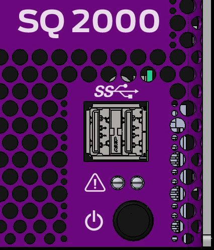
LiveTouch
                                                                                          Installation Manual

Important Safety Information
          This section provides important safety guidelines for operators and service personnel.
          Specific warnings and cautions appear throughout the manual where they apply. Please
          read and follow this important information, especially those instructions related to the risk
          of electric shock or injury to persons.

Symbols and Their Meanings

                        Indicates that dangerous high voltage is present within the equipment
                        enclosure that may be of sufficient magnitude to constitute a risk of electric
                        shock.

                        Indicates that the user, operator or service technician should refer to the product
                        manuals for important operating, maintenance, or service instructions.

                        This is a prompt to note the fuse rating when replacing fuses. The fuse
                        referenced in the text must be replaced with one having the ratings indicated.

                        Identifies a protective grounding terminal which must be connected to earth
                        ground prior to making any other equipment connections.

                        Identifies an external protective grounding terminal which may be connected to
                        earth ground as a supplement to an internal grounding terminal.

                        Indicates that static sensitive components are present, which may be damaged
                        by electrostatic discharge. Use anti-static procedures, equipment and surfaces
                        during servicing.

                        Indicates that the equipment has more than one power supply cord, and that all
                        power supply cords must be disconnected before servicing to avoid electric
                        shock.

                        The presence of this symbol in or on Grass Valley equipment means that it has
                        been tested and certified as complying with applicable Underwriters Laboratory
                        (UL) regulations and recommendations for USA.

                        The presence of this symbol in or on Grass Valley equipment means that it has
                        been tested and certified as complying with applicable Canadian Standard
                        Association (CSA) regulations and recommendations for USA/Canada.

                        The presence of this symbol in or on Grass Valley equipment means that it has
                        been tested and certified as complying with applicable Underwriters Laboratory
                        (UL) regulations and recommendations for USA/Canada.

                                                                                                           iii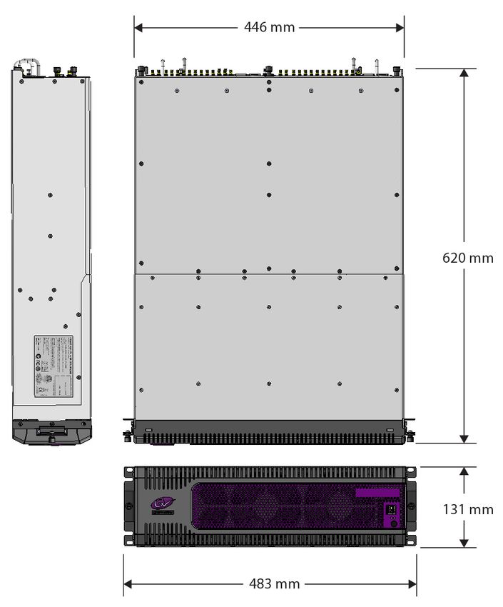
Notices

                        The presence of this symbol in or on Grass Valley equipment means that it has
                        been tested and certified as complying with applicable Intertek Testing Services
                        regulations and recommendations for USA/Canada.

                        The presence of this symbol in or on Grass Valley equipment means that it has
                        been tested and certified to applicable safety test standards for USA/Canada by
                        TÜV SÜD.

                        The presence of this symbol in or on Grass Valley product means that it complies
                        with applicable UK safety and EMC requirements.

                        The presence of this symbol in or on Grass Valley product means that it complies
                        with all applicable European Union (CE) directives.

                        The presence of this symbol in or on Grass Valley product means that it complies
                        with safety of laser product applicable standards.

Warnings
                   A warning indicates a possible hazard to personnel, which may cause injury or
                   death. Observe the following general warnings when using or working on this
                   equipment:
           •   Appropriately listed/certified mains supply power cords must be used for the
               connection of the equipment to the rated mains voltage.
           •   This product relies on the building's installation for short-circuit (over-current)
               protection. Ensure that a fuse or circuit breaker for the rated mains voltage is used on
               the phase conductors.
           •   Any instructions in this manual that require opening the equipment cover or enclosure
               are for use by qualified service personnel only.
           •   Do not operate the equipment in wet or damp conditions.
           •   This equipment is grounded through the grounding conductor of the power cords. To
               avoid electrical shock, plug the power cords into a properly wired receptacle before
               connecting the equipment inputs or outputs.
           •   Route power cords and other cables so they are not likely to be damaged. Properly
               support heavy cable bundles to avoid connector damage.
           •   Disconnect power before cleaning the equipment. Do not use liquid or aerosol
               cleaners; use only a damp cloth.
           •   Dangerous voltages may exist at several points in this equipment. To avoid injury, do
               not touch exposed connections and components while power is on.
           •   High leakage current may be present. Earth connection of product is essential before
               connecting power.
           •   Prior to servicing, remove jewelry such as rings, watches, and other metallic objects.

iv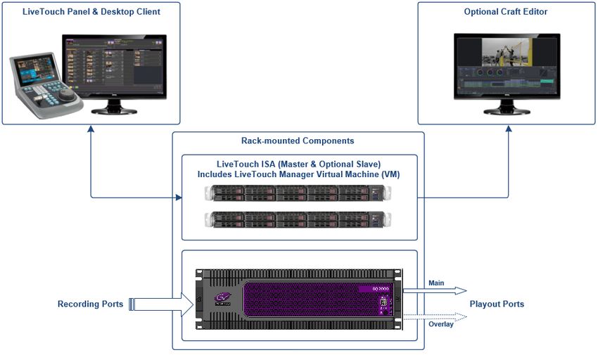
LiveTouch
                                                                                       Installation Manual

             • To avoid fire hazard, use only the fuse type and rating specified in the service
               instructions for this product, or on the equipment.
             • To avoid explosion, do not operate this equipment in an explosive atmosphere.
             • Use proper lift points. Do not use door latches to lift or move equipment.
             • Avoid mechanical hazards. Allow all rotating devices to come to a stop before servicing.
             • Have qualified service personnel perform safety checks after any service.

Cautions
                     A caution indicates a possible hazard to equipment that could result in equipment
                     damage. Observe the following cautions when operating or working on this
                     equipment:
             •   This equipment is meant to be installed in a restricted access location.
             •   When installing this equipment, do not attach the power cord to building surfaces.
             •   Products that have no on/off switch, and use an external power supply must be
                 installed in proximity to a main power outlet that is easily accessible.
             •   Use the correct voltage setting. If this product lacks auto-ranging power supplies,
                 before applying power ensure that each power supply is set to match the power
                 source.
             •   Provide proper ventilation. To prevent product overheating, provide equipment
                 ventilation in accordance with the installation instructions.
             •   Do not operate with suspected equipment failure. If you suspect product damage or
                 equipment failure, have the equipment inspected by qualified service personnel.
             •   To reduce the risk of electric shock, do not perform any servicing other than that
                 contained in the operating instructions unless you are qualified to do so. Refer all
                 servicing to qualified service personnel.
             •   This unit may have more than one power supply cord. Disconnect all power supply
                 cords before servicing to avoid electric shock.
             •   Follow static precautions at all times when handling this equipment. Servicing should
                 be done in a static-free environment.
             •   To reduce the risk of electric shock, plug each power supply cord into separate branch
                 circuits employing separate service grounds.

Electrostatic Discharge (ESD) Protection
                   Electrostatic discharge occurs when electronic components are improperly
                   handled and can result in intermittent failure or complete damage adversely
                   affecting an electrical circuit. When you remove and replace any card from a frame
           always follow ESD-prevention procedures:
             • Ensure that the frame is electrically connected to earth ground through the power cord
               or any other means if available.
             • Wear an ESD wrist strap ensuring that it makes good skin contact. Connect the
               grounding clip to an unpainted surface of the chassis frame to safely ground unwanted
               ESD voltages. If no wrist strap is available, ground yourself by touching the unpainted
               metal part of the chassis.

                                                                                                        v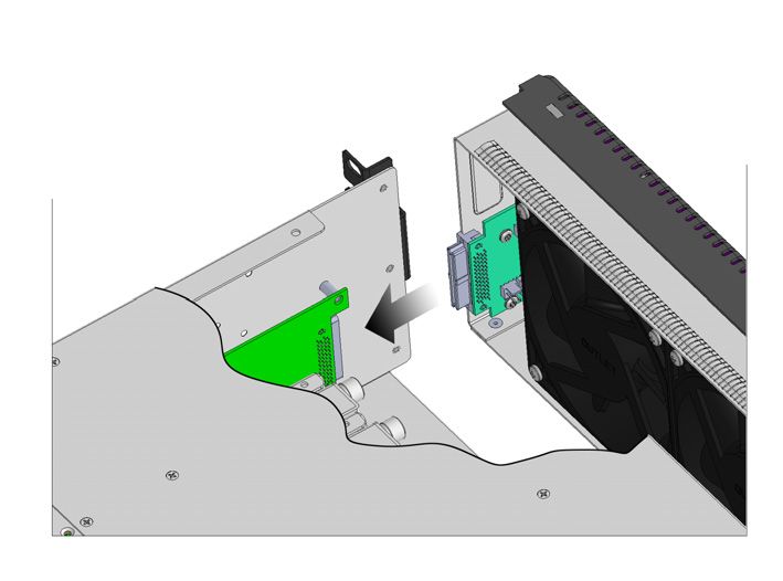
Notices

             • For safety, periodically check the resistance value of the antistatic strap, which should
               be between 1 and 10 megohms.
             • When temporarily storing a card make sure it is placed in an ESD bag.
             • Cards in an earth grounded metal frame or casing do not require any special ESD
               protection.

Battery Handling
                   This product may include a backup battery. There is a danger of explosion if the
                   battery is replaced incorrectly. Replace the battery only with the same or equivalent
                   type recommended by the manufacturer. Dispose of used batteries according to
           the manufacturer’s instructions. Before disposing of your Grass Valley equipment, please
           review the Disposal and Recycling Information at:
             http://www.grassvalley.com/assets/media/5692/Take-Back_Instructions.pdf

Cautions for LCD and TFT Displays
                   Excessive usage may harm your vision. Rest for 10 minutes for every 30 minutes of
                   usage.
                    If the LCD or TFT glass is broken, handle glass fragments with care when disposing
           of them. If any fluid leaks out of a damaged glass cell, be careful not to get the liquid crystal
           fluid in your mouth or skin. If the liquid crystal touches your skin or clothes, wash it off
           immediately using soap and water. Never swallow the fluid. The toxicity is extremely low
           but caution should be exercised at all times.

Mesures de sécurité et avis importants
           La présente section fournit des consignes de sécurité importantes pour les opérateurs et le
           personnel de service. Des avertissements ou mises en garde spécifiques figurent dans le
           manuel, dans les sections où ils s’appliquent. Prenez le temps de bien lire les consignes et
           assurez-vous de les respecter, en particulier celles qui sont destinées à prévenir les
           décharges électriques ou les blessures.

Signification des symboles utilisés

                         Signale la présence d’une tension élevée et dangereuse dans le boîtier de
                         l’équipement ; cette tension peut être suffisante pour constituer un risque de
                         décharge électrique.

                         Avertit l'utilisateur, l’opérateur ou le technicien de maintenance que des
                         instructions importantes relatives à l'utilisation et à l'entretien se trouvent dans
                         la documentation accompagnant l’équipement.

vi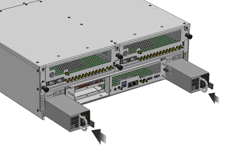
LiveTouch
                                                                    Installation Manual

Invite l'utilisateur, l’opérateur ou le technicien de maintenance à prendre note du
calibre du fusible lors du remplacement de ce dernier. Le fusible auquel il est fait
référence dans le texte doit être remplacé par un fusible du même calibre.

Identifie une borne de mise à la terre de protection. Il faut relier cette borne à la
terre avant d’effectuer toute autre connexion à l’équipement.

Identifie une borne de mise à la terre externe qui peut être connectée en tant
que borne de mise à la terre supplémentaire.

Signale la présence de composants sensibles à l’électricité statique et qui sont
susceptibles d’être endommagés par une décharge électrostatique. Utilisez des
procédures, des équipements et des surfaces antistatiques durant les
interventions d’entretien.

Le symbole ci-contre signifie que l’appareil comporte plus d’un cordon
d'alimentation et qu’il faut débrancher tous les cordons d'alimentation avant
toute opération d’entretien, afin de prévenir les chocs électriques.

La marque UL certifie que l’appareil visé a été testé par Underwriters Laboratory
(UL) et reconnu conforme aux exigences applicables en matière de sécurité
électrique en vigueur au Canada et aux États-Unis.

La marque C-CSA-US certifie que l’appareil visé a été testé par l'Association
canadienne de normalisation (CSA) et reconnu conforme aux exigences
applicables en matière de sécurité électrique en vigueur au Canada et aux États-
Unis.

La marque C-UL-US certifie que l’appareil visé a été testé par Underwriters
Laboratory (UL) et reconnu conforme aux exigences applicables en matière de
sécurité électrique en vigueur au Canada et aux États-Unis.

La marque ETL Listed d’Intertek pour le marché Nord-Américain certifie que
l’appareil visé a été testé par Intertek et reconnu conforme aux exigences
applicables en matière de sécurité électrique en vigueur au Canada et aux États-
Unis.

La présence de ce symbole à l'intérieur ou l'extérieur d'un équipement Grass
Valley signifie qu'il a été testé et certifié selon les normes applicables de sécurité
pour les É.-U/Canada par TÜV SÜD.

La présence de ce symbole sur un appareil Grass Valley signifie qu'il est conforme
aux exigences applicables du Royaume-Uni en matière de sécurité et de
compatibilité électromagnétique.

                                                                                    vii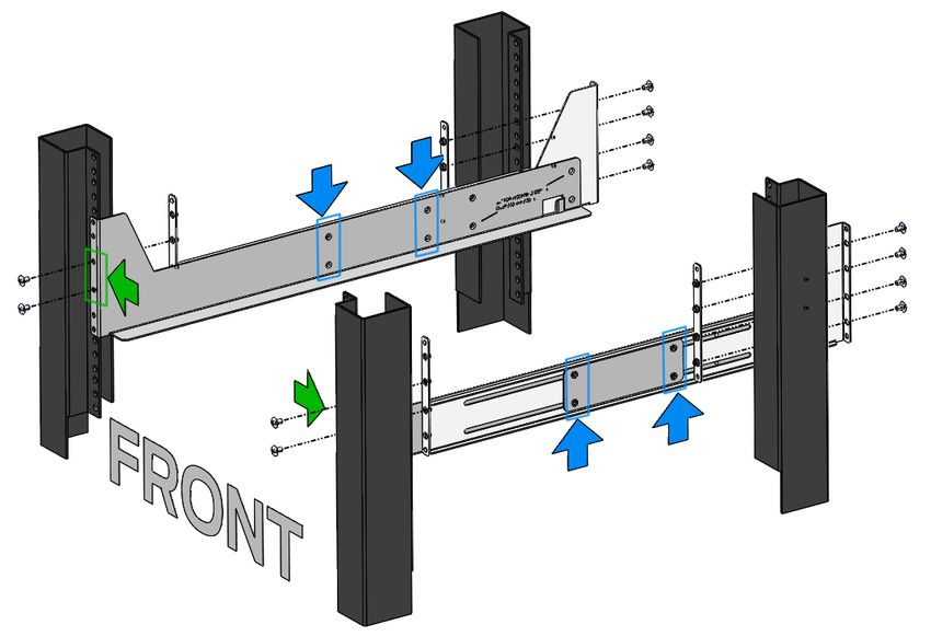
Notices

                         Le marquage CE indique que l’appareil visé est conforme aux exigences
                         essentielles des directives applicables de l’Union européenne en matière de
                         sécurité électrique, de compatibilité électromagnétique et de conformité
                         environnementale.

                         Le symbole ci-contre sur un appareil Grass Valley ou à l’intérieur de l’appareil
                         indique qu’il est conforme aux normes applicables en matière de sécurité laser.

Avertissements
                    Les avertissements signalent des conditions ou des pratiques susceptibles
                    d’occasionner des blessures graves, voire fatales. Veuillez vous familiariser avec les
                    avertissements d’ordre général ci-dessous :
           •   Un cordon d’alimentation dûment homologué doit être utilisé pour connecter
               l’appareil à une tension de secteur de 120 V CA ou 240 V CA.
           •   La protection de ce produit contre les courts-circuits (surintensités) dépend de
               l’installation électrique du bâtiment. Assurez-vous qu'un fusible ou un disjoncteur pour
               120 V CA ou 240 V CA est utilisé sur les conducteurs de phase.
           •   Dans le présent manuel, toutes les instructions qui nécessitent d’ouvrir le couvercle de
               l’équipement sont destinées exclusivement au personnel technique qualifié.
           •   N’utilisez pas cet appareil dans un environnement humide.
           •   Cet équipement est mis à la terre par le conducteur de mise à la terre des cordons
               d’alimentation. Pour éviter les chocs électriques, branchez les cordons d’alimentation
               sur une prise correctement câblée avant de brancher les entrées et sorties de
               l’équipement.
           •   Acheminez les cordons d’alimentation et autres câbles de façon à ce qu’ils ne risquent
               pas d’être endommagés. Supportez correctement les enroulements de câbles afin de
               ne pas endommager les connecteurs.
           •   Coupez l’alimentation avant de nettoyer l’équipement. Ne pas utiliser de nettoyants
               liquides ou en aérosol. Utilisez uniquement un chiffon humide.
           •   Des tensions dangereuses peuvent exister en plusieurs points dans cet équipement.
               Pour éviter toute blessure, ne touchez pas aux connexions ou aux composants exposés
               lorsque l’appareil est sous tension.
           •   Avant de procéder à toute opération d’entretien ou de dépannage, enlevez tous vos
               bijoux (notamment vos bagues, votre montre et autres objets métalliques).
           •   Pour éviter tout risque d’incendie, utilisez uniquement les fusibles du type et du calibre
               indiqués sur l’équipement ou dans la documentation qui l’accompagne.
           •   Ne pas utiliser cet appareil dans une atmosphère explosive.
           •   Présence possible de courants de fuite. Un raccordement à la masse est indispensable
               avant la mise sous tension.
           •   Après tout travail d’entretien ou de réparation, faites effectuer des contrôles de sécurité
               par le personnel technique qualifié.

viii
LiveTouch
Installation Manual
Mises en garde
Les mises en garde signalent des conditions ou des pratiques susceptibles
d’endommager l’équipement. Veuillez vous familiariser avec les mises en garde ci-
dessous :
• L’appareil est conçu pour être installé dans un endroit à accès restreint.
• Au moment d’installer l’équipement, ne fixez pas les cordons d’alimentation aux
surfaces intérieures de l’édifice.
• Les produits qui n'ont pas d’interrupteur marche-arrêt et qui disposent d’une source
d’alimentation externe doivent être installés à proximité d'une prise de courant facile
d’accès.
• Si l’équipement n’est pas pourvu d’un modules d’alimentation auto-adaptables, vérifiez
la configuration de chacun des modules d'alimentation avant de les mettre sous
tension.
• Assurez une ventilation adéquate. Pour éviter toute surchauffe du produit, assurez une
ventilation de l’équipement conformément aux instructions d’installation.
• N’utilisez pas l’équipement si vous suspectez un dysfonctionnement du produit. Faites-
le inspecter par un technicien qualifié.
• Pour réduire le risque de choc électrique, n'effectuez pas de réparations autres que
celles qui sont décrites dans le présent manuel, sauf si vous êtes qualifié pour le faire.
Confiez les réparations à un technicien qualifié. La maintenance doit se réaliser dans un
milieu libre d’électricité statique.
• L’appareil peut comporter plus d’un cordon d'alimentation. Afin de prévenir les chocs
électriques, débrancher tous les cordons d'alimentation avant toute opération
d’entretien.
• Veillez à toujours prendre les mesures de protection antistatique appropriées quand
vous manipulez l’équipement.
• Pour réduire le risque de choc électrique, branchez chaque cordon d'alimentation dans
des circuits de dérivation distincts utilisant des zones de service distinctes.
Protection contre les décharges électrostatiques (DES)
Une décharge électrostatique peut se produire lorsque des composants
électroniques ne sont pas manipulés de manière adéquate, ce qui peut entraîner
des défaillances intermittentes ou endommager irrémédiablement un circuit
électrique. Au moment de remplacer une carte dans un châssis, prenez toujours les
mesures de protection antistatique appropriées :
• Assurez-vous que le châssis est relié électriquement à la terre par le cordon
d'alimentation ou tout autre moyen disponible.
• Portez un bracelet antistatique et assurez-vous qu'il est bien en contact avec la peau.
Connectez la pince de masse à une surface non peinte du châssis pour détourner à la
terre toute tension électrostatique indésirable. En l’absence de bracelet antistatique,
déchargez l’électricité statique de votre corps en touchant une surface métallique non
peinte du châssis.
• Pour plus de sécurité, vérifiez périodiquement la valeur de résistance du bracelet
antistatique. Elle doit se situer entre 1 et 10 mégohms.
ixNotices
• Si vous devez mettre une carte de côté, assurez-vous de la ranger dans un sac
protecteur antistatique.
• Les cartes qui sont reliées à un châssis ou boîtier métallique mis à la terre ne
nécessitent pas de protection antistatique spéciale.
Manipulation de la pile
Ce produit peut inclure une pile de sauvegarde. Il y a un risque d'explosion si la pile
est remplacée de manière incorrecte. Remplacez la pile uniquement par un modèle
identique ou équivalent recommandé par le fabricant. Disposez des piles usagées
conformément aux instructions du fabricant. Avant de vous séparer de votre équipement
Grass Valley, veuillez consulter les informations de mise au rebut et de recyclage à:
http://www.grassvalley.com/assets/media/5692/Take-Back_Instructions.pdf
Précautions pour les écrans LCD et TFT
Regarder l’écran pendant une trop longue période de temps peut nuire à votre
vision. Prenez une pause de 10 minutes, après 30 minutes d’utilisation.
Si l'écran LCD ou TFT est brisé, manipulez les fragments de verre avec précaution au
moment de vous en débarrasser. veillez à ce que le cristal liquide n'entre pas en contact
avec la peau ou la bouche. En cas de contact avec la peau ou les vêtements, laver
immédiatement à l'eau savonneuse. Ne jamais ingérer le liquide. La toxicité est
extrêmement faible, mais la prudence demeure de mise en tout temps.
Environmental Information
European (CE) WEEE directive.
This symbol on the product(s) means that at the end of life disposal it should not be mixed
with general waste.
Visit www.grassvalley.com for recycling information.
Grass Valley believes this environmental information to be correct but cannot guarantee its
completeness or accuracy since it is based on data received from sources outside our
company. All specifications are subject to change without notice.
If you have questions about Grass Valley environmental and social involvement (WEEE,
RoHS, REACH, etc.), please contact us at environment@grassvalley.com .
xLiveTouch
Installation Manual
Lithium Batteries
Battery Warning
Your Grass Valley equipment usually comes with at least one button battery located on the main
printed circuit board. The batteries are used for backup and should not need to be replaced
during the lifetime of the equipment.
Battery Disposal
Before disposing of your Grass Valley equipment, please remove the battery as follows:
1 Make sure the AC adapter / power Cord is unplugged from the power outlet.
2 Remove the protective cover from your equipment.
3 Gently remove the battery from its holder using a blunt instrument for leverage such as
a screwdriver if necessary. In some cases the battery will need to be desoldered from
the PCB.
4 Dispose of the battery and equipment according to your local environmental laws and
guidelines.
WARNING
• Be careful not to short-circuit the battery by adhering to the
appropriate safe handling practices.
• Do not dispose of batteries in a fire as they may explode.
• Batteries may explode if damaged or overheated.
• Do not dismantle, open or shred batteries.
• In the event of a battery leak, do not allow battery liquid to come in
contact with skin or eyes.
• Seek medical help immediately in case of ingestion, inhalation, skin
or eye contact, or suspected exposure to the contents of an opened
battery.
xiNotices
Laser Safety - Fiber QSFP Modules Warning
LASER SAFETY
The average optical output power does not exceed 0 dBm (1mW) under normal operating
conditions. Unused optical outputs should be covered to prevent direct exposure to the
laser beam.
Even though the power of these lasers is low, the beam should be treated with caution
and common sense because it is intense and concentrated. Laser radiation can cause
irreversible and permanent damage of eyesight. Please read the following guidelines
carefully:
• Make sure that a fiber is connected to the board's fiber outputs before power is
applied. If a fiber cable (e.g. patchcord) is already connected to an output, make sure
that the cable's other end is connected, too, before powering up the board.
• Do not look in the end of a fiber to see if light is coming out. The laser wavelengths
being used are totally invisible to the human eye and can cause permanent damage.
Always use optical instrumentation, such as an optical power meter, to verify light
output.
xiiLiveTouch
Installation Manual
Safety and EMC Standards
This equipment complies with the following standards:
Safety Standards
Information Technology Equipment - Safety Part 1
Audio/video, information and communication technology equipment - Part 1: Safety
requirements
IEC 62368-1: 2014, EN 62368-1: 2014, UL 62368-1: 2014, CAN/CSA C22.2 No 62368-1: 2014,
AS/NZS 62368-1: 2018.
EMC Standards
This unit conforms to the following standards:
EN55032:2015 (Class A)
Electromagnetic Compatibility of multimedia equipment - Emission requirements
EN61000-3-2:2014 (Class A)
Electromagnetic Compatibility - Limits for harmonic current emissions
EN61000-3-3:2013
Electromagnetic Compatibility - Limits of voltage changes, voltage fluctuations and flicker
EN55035:2017
Electromagnetic Compatibility of Multimedia Equipment. Immunity requirements.
WARNING
This equipment is compliant with Class A of CISPR 32. In a residential
environment this equipment may cause radio interference.
FCC / CFR 47:Part 15 (Class A)
Federal Communications Commission Rules Part 15, Subpart B
Caution to the user that changes or modifications not expressly approved by the party
responsible for compliance could void the user's authority to operate the equipment.
xiiiNotices
Note: This equipment has been tested and found to comply with the
limits for a Class A digital device, pursuant to part 15 of the FCC
Rules. These limits are designed to provide reasonable
protection against harmful interference when the equipment is
operated in a commercial environment.
This equipment generates, uses, and can radiate radio
frequency energy and, if not installed and used in accordance
with the instruction manual, may cause harmful interference to
radio communications.
Operation of this equipment in a residential area is likely to
cause harmful interference in which case the user will be
required to correct the interference at his own expense.
EMC Performance of Cables and Connectors
Grass Valley products are designed to meet or exceed the requirements of the appropriate
European EMC standards. In order to achieve this performance in real installations it is
essential to use cables and connectors with good EMC characteristics.
All signal connections (including remote control connections) shall be made with screened
cables terminated in connectors having a metal shell. The cable screen shall have a large-
area contact with the metal shell.
SIGNAL/DATA PORTS
For unconnected signal/data ports on the unit, fit shielding covers. For example, fit EMI
blanking covers to SFP+ type ports; and fit 75 Ώ RF terminators to BNC type ports.
COAXIAL CABLES
Coaxial cables connections (particularly serial digital video connections) shall be made with
high-quality double-screened coaxial cables such as Belden 8281 or BBC type PSF1/2M and
Belden 1694A (for 3Gbps).
D-TYPE CONNECTORS
D-type connectors shall have metal shells making good RF contact with the cable screen.
Connectors having “dimples” which improve the contact between the plug and socket
shells, are recommended.
xivTable of Contents
FCC Compliance. . . . . . . . . . . . . . . . . . . . . . . . . . . . . . . . . . . . . . . . . . . . . . . . . . . . . . . . . . . . . . . . . . . ii
Patent Information . . . . . . . . . . . . . . . . . . . . . . . . . . . . . . . . . . . . . . . . . . . . . . . . . . . . . . . . . . . . . . . . ii
Copyright and Trademark Notice. . . . . . . . . . . . . . . . . . . . . . . . . . . . . . . . . . . . . . . . . . . . . . . . . . . ii
Battery Disposal . . . . . . . . . . . . . . . . . . . . . . . . . . . . . . . . . . . . . . . . . . . . . . . . . . . . . . . . . . . . . .xi
Laser Safety - Fiber QSFP Modules Warning . . . . . . . . . . . . . . . . . . . . . . . . . . . . . . . . . . . xii
Safety and EMC Standards . . . . . . . . . . . . . . . . . . . . . . . . . . . . . . . . . . . . . . . . . . . . . . . . . . . . . . . xiii
Safety Standards . . . . . . . . . . . . . . . . . . . . . . . . . . . . . . . . . . . . . . . . . . . . . . . . . . . . . . . . . . . . xiii
EMC Standards . . . . . . . . . . . . . . . . . . . . . . . . . . . . . . . . . . . . . . . . . . . . . . . . . . . . . . . . . . . . . . xiii
EMC Performance of Cables and Connectors . . . . . . . . . . . . . . . . . . . . . . . . . . . . . . . . . xiv
1 Introduction . . . . . . . . . . . . . . . . . . . . . . . . . . . . . . . . . . . . . . . . . . . 1
About this Manual . . . . . . . . . . . . . . . . . . . . . . . . . . . . . . . . . . . . . . . . . . . . . . . . . . . . . . . . . . . . . . . . . 1
Overview. . . . . . . . . . . . . . . . . . . . . . . . . . . . . . . . . . . . . . . . . . . . . . . . . . . . . . . . . . . . . . . . . . . . . . . . . . 2
Clipnet Media Network. . . . . . . . . . . . . . . . . . . . . . . . . . . . . . . . . . . . . . . . . . . . . . . . . . . . . . . . 2
Advanced Super Motion Support. . . . . . . . . . . . . . . . . . . . . . . . . . . . . . . . . . . . . . . . . . . . . . 2
A Native UHD and HDR Platform without Sacrifice . . . . . . . . . . . . . . . . . . . . . . . . . . . . . 3
Instant, Integrated Editing . . . . . . . . . . . . . . . . . . . . . . . . . . . . . . . . . . . . . . . . . . . . . . . . . . . . 3
Summary of the LiveTouch (SQ2000) Server Features . . . . . . . . . . . . . . . . . . . . . . . . . . . 4
Overview of LiveTouch System Components . . . . . . . . . . . . . . . . . . . . . . . . . . . . . . . . . . . . . . . 5
LiveTouch Server . . . . . . . . . . . . . . . . . . . . . . . . . . . . . . . . . . . . . . . . . . . . . . . . . . . . . . . . . . . . . . 5
LiveTouch Panel. . . . . . . . . . . . . . . . . . . . . . . . . . . . . . . . . . . . . . . . . . . . . . . . . . . . . . . . . . . . . . . 5
LiveTouch Desktop Client PC . . . . . . . . . . . . . . . . . . . . . . . . . . . . . . . . . . . . . . . . . . . . . . . . . . 5
LiveTouch ISA . . . . . . . . . . . . . . . . . . . . . . . . . . . . . . . . . . . . . . . . . . . . . . . . . . . . . . . . . . . . . . . . . 5
LiveTouch Manager VM. . . . . . . . . . . . . . . . . . . . . . . . . . . . . . . . . . . . . . . . . . . . . . . . . . . . . . . . 6
LiveTouch Search VM (Web Bin). . . . . . . . . . . . . . . . . . . . . . . . . . . . . . . . . . . . . . . . . . . . . . . . 6
2 Connecting the LiveTouch Components. . . . . . . . . . . . . . . . . . 7
Overview. . . . . . . . . . . . . . . . . . . . . . . . . . . . . . . . . . . . . . . . . . . . . . . . . . . . . . . . . . . . . . . . . . . . . . . . . . 7
LiveTouch (SQ2000) Server Connectors. . . . . . . . . . . . . . . . . . . . . . . . . . . . . . . . . . . . . . . . . . . . . 8
Removing the SQ2000 Server front door . . . . . . . . . . . . . . . . . . . . . . . . . . . . . . . . . . . . . . . 9
Connecting the LiveTouch Server . . . . . . . . . . . . . . . . . . . . . . . . . . . . . . . . . . . . . . . . . . . . .10
3 Environment and Location . . . . . . . . . . . . . . . . . . . . . . . . . . . . . 13
Environmental Considerations . . . . . . . . . . . . . . . . . . . . . . . . . . . . . . . . . . . . . . . . . . . . . . . . . . . .13
Rack-mounting Considerations . . . . . . . . . . . . . . . . . . . . . . . . . . . . . . . . . . . . . . . . . . . . . . .14
Component Cooling. . . . . . . . . . . . . . . . . . . . . . . . . . . . . . . . . . . . . . . . . . . . . . . . . . . . . . . . . .15
Air Flow through the LiveTouch (SQ2000) Server. . . . . . . . . . . . . . . . . . . . . . . . . . . . . . 15
1Table of Contents
4 Power Supplies . . . . . . . . . . . . . . . . . . . . . . . . . . . . . . . . . . . . . . . . 17
Internal Power Supplies. . . . . . . . . . . . . . . . . . . . . . . . . . . . . . . . . . . . . . . . . . . . . . . . . . . . . . . . . . .17
Checking the Power Supplies . . . . . . . . . . . . . . . . . . . . . . . . . . . . . . . . . . . . . . . . . . . . . . . . 18
Removing the Power Supplies. . . . . . . . . . . . . . . . . . . . . . . . . . . . . . . . . . . . . . . . . . . . . . . . 18
5 Specifications . . . . . . . . . . . . . . . . . . . . . . . . . . . . . . . . . . . . . . . . . 19
Overview. . . . . . . . . . . . . . . . . . . . . . . . . . . . . . . . . . . . . . . . . . . . . . . . . . . . . . . . . . . . . . . . . . . . . . . . .19
LiveTouch (SQ2000) Server Specifications . . . . . . . . . . . . . . . . . . . . . . . . . . . . . . . . . . . . . . . . .19
LiveTouch (SQ2000) Server Interface Cards . . . . . . . . . . . . . . . . . . . . . . . . . . . . . . . . . . . .20
Supported Video Compression Formats . . . . . . . . . . . . . . . . . . . . . . . . . . . . . . . . . . . . . . .22
Supported Proxy Compression Formats . . . . . . . . . . . . . . . . . . . . . . . . . . . . . . . . . . . . . . .22
Supported Audio Formats . . . . . . . . . . . . . . . . . . . . . . . . . . . . . . . . . . . . . . . . . . . . . . . . . . . .22
Environmental Specifications . . . . . . . . . . . . . . . . . . . . . . . . . . . . . . . . . . . . . . . . . . . . . . . . .23
Power Specifications . . . . . . . . . . . . . . . . . . . . . . . . . . . . . . . . . . . . . . . . . . . . . . . . . . . . . . . . .23
Reference Signal Specifications . . . . . . . . . . . . . . . . . . . . . . . . . . . . . . . . . . . . . . . . . . . . . . .24
Storage Option Specifications . . . . . . . . . . . . . . . . . . . . . . . . . . . . . . . . . . . . . . . . . . . . . . . .24
Providing Information to Grass Valley . . . . . . . . . . . . . . . . . . . . . . . . . . . . . . . . . . . . . . . . . . . . .25
Basic Information. . . . . . . . . . . . . . . . . . . . . . . . . . . . . . . . . . . . . . . . . . . . . . . . . . . . . . . . . . . . .25
Software Application . . . . . . . . . . . . . . . . . . . . . . . . . . . . . . . . . . . . . . . . . . . . . . . . . . . . . . . . .25
Your Contact Details. . . . . . . . . . . . . . . . . . . . . . . . . . . . . . . . . . . . . . . . . . . . . . . . . . . . . . . . . .25
Customer Support. . . . . . . . . . . . . . . . . . . . . . . . . . . . . . . . . . . . . . . . . . . . . . . . . . . . . . . . . . . .25
Contact Us . . . . . . . . . . . . . . . . . . . . . . . . . . . . . . . . . . . . . . . . . . . . . . . 27
2Introduction
About this Manual
This installation manual help you through the physical installation of your LiveTouch
SQ2000 Server, and advise you of all relevant safety aspects.
LiveTouch (SQ2000) Server
Fig. 1-1: Example of LiveTouch SQ2000 Server and Replay System Components
1Introduction
Overview
Overview
LiveTouch (SQ2000 Server) is the next generation server platform in the sQ/LiveTouch
family which will initially target high performance replay workflows. LiveTouch (sQ2000) is
an ultra-high density video server which will include a market leading feature set in instant
replay and high performance video server applications.
Each LiveTouch (SQ2000) Server is factory configured as a HD (high definition) or UHD
(ultra-high definition) networked distribution server employing industry standard
compression systems. Features include:
• The highest port density of any replay server on the market
• 12 ports/server in UHD
• 24 ports/server in HD & 3G
• Dual redundant 100G - 2110 IP Interfaces per I/O card (200G total). The most powerful
IP architecture on the market enabling unique I/O configurations and headroom to
expand even further in the future
• Clipnet media network interfaces for inter-server streaming and media sharing
workflows
• Access any angle, anywhere instantaneously with instant system wide access to any
angle on the network with Clipnet
• Up to internal 64TB SSD storage to better accommodate the ultra-high port count. The
most internal storage available on any replay server in the market today.
• Instant, integrated craft editing available at every operator workstation using Frame
Magic technology. Instantly load any replay clip or playlist into a fully featured craft
edit timeline.
• Unique powerful, flexible processing in mixed format workflows. Dynamically mix
UHD, 3G and HD content on the same playout port. LiveTouch also provides the
capability to convert between SDR and HDR on the fly to handle multiple broadcast
deliverables simultaneously. LiveTouch even allows cross mapping between different
types of HDR.
Clipnet Media Network
The LiveTouch (SQ2000) Clipnet provides a centralized ingest model for operators, allowing
unrestricted access to content anywhere on the system. Access any angle, anywhere
instantly with LiveTouch. Clipnet connections allows replay operators to stream remote
cameras from any server instantaneously. This removes any delays or complexity when
spreading complex workflows across multiple servers.
Advanced Super Motion Support
LiveTouch (SQ2000) supports a wide range of super motion cameras to support your live
sports production. Get ultra-smooth playback from 2x to 10x super motion in HD and 3x
super motion in UHD. Super motion inputs are easy to configure via the SQ2000 web page
saving valuable time before live productions.
2LiveTouch
Technical Guide
A Native UHD and HDR Platform without Sacrifice
LiveTouch (sQ2000) supports UHD workflows without drastically sacrificing port count or
tool set. LiveTouch SQ2000 supports 12 channels of UHD per server and allows a
comprehensive tool set in both editing and replay workflows using XAVC Class 300.
Working with multiple resolutions is also a breeze with flexible multi-resolution support.
Work with a mixture of HD and UHD on the same server with instant, dynamic up-res and
down-res on playout.
SQ2000 also features ultra-flexible HDR support of up to 24 channels of 1080p or 12
Channels of UHD in Rec. 2020. LiveTouch SQ2000 can also seamlessly handle mixed SDR
and HDR inputs. Many sports productions require multiple deliverables is different
resolutions and color spaces, LiveTouch 2000 is the perfect replay solution in a mixed
environment allowing ultimate flexibility.
Instant, Integrated Editing
LiveTouch is the only replay solution on the market to allow instant media sharing between
replay and editing. Using Grass Valley Frame Magic technology, any replay clip or highlight
playlist can be instantly loaded into a fully featured craft editor. This eliminates any latency
between replay operators and editors allowing unmatched speed for creative workflows.
Instantly feed replay assets through the production chain and take advantage of a powerful
editing tool set which delivers both simple edits and advanced effects for rapid turnaround
during live production.
3Introduction
Summary of the LiveTouch (SQ2000) Server Features
Summary of the LiveTouch (SQ2000) Server Features
The following table summarizes the main features of the LiveTouch Server:
Item Description
General
Video Channels • Up to 24 HD
• Up to 12 UHD
Clipnet Network • 2x 10G (Copper and Optical)
Native Multi-format • AVC Intra
Support • XAVC Class 300 (UHD)
• DNxHD
IP • ST2110
• Dual 100G (per I/O) Card
• NMOS IS-04, IS-05
SDI • 1.5G SDI, 3G SDI, 12G SDI
HDR • S-Log, HLG, PQ
Redundancy • Dual-redundant PSUs
Audio • Embedded Audio
• External Audio - MADI
UHD Features
Channels per server • 8x 12G Inputs
• 4x 12G Outputs
• 4x 3G Overlay Outputs
Storage • Internal Storage - Up to 64TB
Browse/Proxy • H.264 and 720p browse workflows for editing and remote access
Agile Codec Support
Resolution • 1080i, 720p, 1080p, UHD
Independent Inputs
and Outputs
Dynamic upscaling on • Set output resolution, with codecs processed on the fly
output
If you have any questions about the installation of your product, refer to the contact details
listed at the rear of this guide.
Note: All diagrams are for illustrative purposes only and may differ
slightly from the purchased product. Grass Valley operates a
policy of continuous improvement and development. Grass Valley
reserves the right to make changes and improvements to any of
the products described in this document without prior notice.
4LiveTouch
Technical Guide
Overview of LiveTouch System Components
LiveTouch Server
LiveTouch (SQ2000) provides an unrivaled channel count in a compact chassis. Utilize 24
channels of 3G or 12 Channels of UHD in a single 3RU mainframe. Each SQ2000 I/O card can
be booted in either IP or SDI, providing flexible I/O profiles for demanding live productions.
Each I/O card offers a dual redundant 100G IP interface for superior connectivity for SMPTE
2110. The I/O card also features 12 compact HD-SDI connections which are all 12G UHD
capable. LiveTouch SQ2000 is the most advanced, high performance video server on the
market today.
LiveTouch Panel
LiveTouch features a dedicated, hardware control panel. Its intuitive touchscreen provides
quick clip selection, speed tools and configurable user options. The panel features familiar
button placement as well as a number pad for fast navigation by clip number and
timecode. The responsive jog wheel provides agile clip navigation and the high-precision T-
bar enables precise control of slow-motion playout.
In addition, the LiveTouch Panel touchscreen provides enables intuitive highlight creation,
navigation and playlist building. The LiveTouch Panel can also host third-party web
applications such as RT Software tOG Sports for enhanced, live sports workflows.
LiveTouch Desktop Client PC
The LiveTouch Panel is paired to a LiveTouch Desktop Client PC, which is offered as turnkey
hardware or as a software only option. The LiveTouch Client software runs on Windows 7 or
Windows 10, as required. The LiveTouch Desktop PC acts as the intermediary between the
LiveTouch Panel and LiveTouch Manager, passing commands over the network to execute
playback operation.
LiveTouch ISA
The LiveTouch Integrated Server Architecture (ISA) system is the LiveTouch system
component which organizes one or more LiveTouch Video Servers to achieve maximum
performance while being tolerant of failures in individual components.
The system can be divided into one or more Zones, each of which has a single or dual-
redundant ISA and one or more LiveTouch Video Servers, each having one or more Pools of
RAID disks, and zero or more Video Channels.
The ISA Manager stores all the Metadata of all clips in its Zone in a well-protected directory.
For user purposes it functions as a single database of all the clips held in that Zone, even
though it may be implemented by a number of different computers to ensure reliability.
Each clip in a Zone is allocated a unique Clip ID when it is created. The ISA stores the
following Metadata items required to describe a Clip:
• ClipID
• Title
• Date of creation.
5Introduction
LiveTouch Manager VM
LiveTouch Manager VM
The LiveTouch Manager is installed as a VM on the ISA Manager. Clients communicate with
the LiveTouch Server through the LiveTouch Manager enabling users to access recordings,
playout ports, clips and playlists.
LiveTouch Search VM (Web Bin)
The LiveTouch Search engine, which provides the Web Bin functionality, is also installed as a
VM on the ISA Manager. The LiveTouch Web Bin allows operators to search, access and
share clips and playlists across the system.
6Connecting the LiveTouch Components
Overview
A standard LiveTouch system comprises the following components:
• LiveTouch Panel
• LiveTouch Desktop Client PC
• LiveTouch Server (SQ2000 Series)
• LiveTouch ISA Managers (Optionally Redundant Pair)
The rear panel connectors for the LiveTouch SQ2000 Server is described in the following
sections.
7Connecting the LiveTouch Components
LiveTouch (SQ2000) Server Connectors
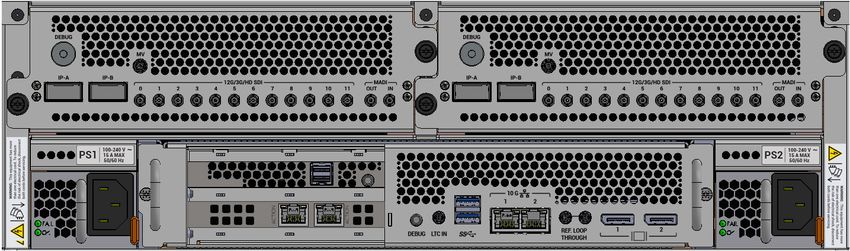
LiveTouch (SQ2000) Server Connectors
Note: The following illustrations of the LiveTouch Server rear panels are
for information only.
1. Debug 1. Debug
4. QSFP28+ 4. QSFP28+
3. 12G/3G/HD SDI 5. MADI 2. I/O Cards 3. 12G/3G/HD SDI 5. MADI
6. PSU 1 1. Debug 9. USB 6. PSU 2
11. CPU Tray
8. LTC In
7. REF and
Loop Through
10. Control Network
Fig. 2-1: LiveTouch (SQ2000) Server Rear Panel Components Interfaces
Key to rear panel items shown in Figure 2-1:
Item Description
LiveTouch (SQ2000) Server Connections
1 Debug connectors
2 I/O Cards
3 0 to 11 - 12G/3G/HD SDI connectors
4 IP-A and IP-B QSFP28+ connectors
5 MADI In/Out
6 PSU 1 and PSU 2
7 REF and Loop Through connector
8 LTC In connector
9 USB connectors
10 Control Network Interfaces
8LiveTouch
Technical Guide
Removing the SQ2000 Server front door
On the left and right sides of the front door and captive securing screws. Unscrew the
screws and carefully pull the door away from the server body. Do not move the door up and
down as you pull away from the server body, as on the right hand side there is an internal
connector that connects the power switch and the USB connectors to an internal interface
board.
Power Switch and
USB connector and
interface board
Power Switch and
USB Connectors
Captive Screws
9Connecting the LiveTouch Components
Connecting the LiveTouch Server
Connecting the LiveTouch Server
Video I/O Video I/O
Clipnet
Connectors
Video Reference
Input
Fig. 2-2: LiveTouch SQ2000 Server Connections
Connect up the LiveTouch SQ2000 Server as follows:
1 Connect the server side of the Clipnet network cable to the Clipnet network adapter.
2 Connect the other end of the Clipnet network cable to the network Gb Switch.
The Clipnet network cable is as follows:
10LiveTouch
Technical Guide
Option Description Details
Dual Ten Copper interface 10G BASE-T
Gigabit – with RJ45 • Network carrier: 10G BASE-T
Copper connections
• Connector type: RJ45
• Cable type: CAT 6A
• Maximum expected operating distance: 100 m
(if patch panels are used, this will reduce)
• Communication protocols: TCP/IP & UDP/IP
Dual Ten Optical interface 10G BASE-SR
Gigabit – with SFP LC • Network carrier: 10G BASE-SR
Optical connections
• Connector type: LC
• Cable type: 50/125 μm or 62.5/125 μm fiber
• Maximum expected operating distance: Up to
300m dependent on type
• Communication protocols: TCP/IP & UDP/IP
Other Clipnet network cables are optionally available.
3 Connect the 1 GbE (RJ45) connector of the Ethernet cable between the Ethernet port
and the network Gb Switch.
This enables the ISA to communicate with the LiveTouch Server, and allows control of
the LiveTouch Server by the ISA Manager.
4 If required, connect the system reference input connector to the reference input
defined on the Server Status Summary webpage in the section Reference & System
Timecode.
Note: The reference input is used for SDI video output timing. The
reference input/output HD-BNC connectors are unterminated.
Terminate the Reference OUT connector with a 75 ohm BNC
termination, unless looped-through to a second LiveTouch Server
- the last device should always be terminated.
5 Connect the serial port for monitoring the LiveTouch SQ2000 server as follows:
• Connect the serial input connector to monitor the status of the CPU.
6 Connect the video cables to the HD-BNC connectors of the video processing cards or,
to the QSFP28+.
Your connections will depend on the requirements and configuration of your system.
7 If required, connect the supplied Linear Timecode (LTC) cable between the LTC
connector and the house timecode.
The LTC input allows a timecode signal to be read by the LiveTouch Server and used as
the system timecode as an alternative to the system reference VITC.
8 An LTC cable of 1 meter in length, is supplied.
11Connecting the LiveTouch Components
Connecting the LiveTouch Server
Note: It is recommended to lock the LTC to the same house reference
signal as the Server.
9 Connect the power cables between the PSU sockets and the power sources mounted in
the rack as described in Chapter 4 Power Supplies.
12Environment and Location
Environmental Considerations
This chapter describes how to install the rack-mounted equipment into the 19 inch rack
environment and LiveTouch desktop client PC and Panel in the desktop environment.
Attention should be paid to the cooling information for the LiveTouch server.
The ambient temperature for all the supplied equipment should not exceed the limits of 5
and 30°C (41 to 86F) at a relative humidity of 10 to 90% (non-condensing).
Installing the equipment in a clean environment with moderate temperature and humidity
will promote a long and trouble-free equipment life.
13Environment and Location
Rack-mounting Considerations
Rack-mounting Considerations
To prevent physical injury when mounting or servicing the LiveTouch (SQ2000) Server in a
rack, you must take special precautions to ensure that the system remains stable.
The following guidelines are provided for your safety:
• Caution: the LiveTouch (SQ2000) server is heavy (28.25Kg) and will need two people to
lift into the rack.
• A rack installation kit is supplied with the LiveTouch SQ2000 Server (as shown below).
• Mount units from the lower part of the rack if these are the only components in the
rack.
• Mount equipment so that uneven mechanical loading causing hazardous conditions
does not arise.
Fig. 3-1: Rack Mount kit Installation.
Blue Arrows:
Loosen these screws while installing the rack kit in a rack, to allow the telescopic effect to
work. Tighten them back once the rack kit is installed.
Green Arrows:
When installing the rack kit, only use the two middle rack mount screw holes as shown in
the diagram. The holes above and below are for the server. All four screw holes can be used
each side on the back.
14LiveTouch
Technical Guide
Component Cooling
Air Flow through the LiveTouch (SQ2000) Server
The following ventilation precautions should be observed for the rack-mounted LiveTouch
(SQ2000) Server:
1 The air intakes on both sides and the cooling fan exhausts at the rear of the units must
not be obstructed - a minimum clearance of 200 mm (8 inches) at the rear of the rack is
essential.
2 Air intakes situated at the front and on both sides, are to allow the inflow of cooling air
and must not be obstructed.
Diagram showing
air flow through the
SQ2000 Server
Airflow through the SQ2000 server is displayed by the red arrows in the diagram above.
15Environment and Location Component Cooling 16
Power Supplies

Internal Power Supplies
         The information below gives an overview of the power supplies used in the LiveTouch
         SQ2000 Server.

                  Note: To reduce the risk of electric shock, plug each power supply cord into
                        separate branch circuits employing separate service grounds.

         The LiveTouch SQ2000 Server is supplied with two power supplies as standard, one
         powering the device and the other providing redundancy.

                  Note: To ensure full dual redundancy, the two power supplies must be
                        powered from independent power sources in the cabinet power rails.

         This symbol indicates that hazardous voltages are present inside the devices. No User
         Serviceable Parts are inside the power supplies. This unit should only be serviced by
         trained personnel.
         Before powering on the LiveTouch Server, make sure that all foam used to protect the
         device in transit is removed.
         The power supplies for the LiveTouch SQ2000 Server are locate at the rear of the unit. The
         power supplies do not have independent on/off switches. The LiveTouch server has an
         On/Off switch on the front panel.

                                  Power Switch

                                                                                                  17
Power Supplies
Internal Power Supplies
Checking the Power Supplies
Power supplies in the LiveTouch Server are hot-swappable. Replacing power supplies
should only be attempted by qualified personnel.
To check that the power supplies are working correctly, when mains power is applied.
• Green LED = system working OK
• Yellow = Warning
• Red = Error
PSU 1 Status LED
PSU 1 Release Clip
Note: Both PSUs have the came configuration
Fig. 4-1: LiveTouch (SQ2000) Server Power Supply Status LEDs
Removing the Power Supplies
The power supply units (PSUs) in the LiveTouch SQ2000 Server are both hot-swappable so
can be individually removed from the unit. Unplug the PSU from the mains and then
remove by pressing the release clip, hold the handle and carefully withdrawing the PSU
from the body of the Server.
Release Clip
Handle
Note: The Power Supplies have NO user serviceable parts inside and if one
should become faulty, it should be replaced immediately.
18Specifications
Overview
This section defines the specifications of the LiveTouch SQ2000 Server.
LiveTouch (SQ2000) Server Specifications
Fig. 5-1: SQ2000 Dimensions
19Specifications
LiveTouch (SQ2000) Server Interface Cards
LiveTouch (SQ2000) Server Interface Cards
Video Network Card
Item Description
Internal Name Clipnet
Interfaces Dual 10GbE (optical or copper)
Protocol GV Clipnet QCP and STTP
Video and Audio Connectors
Inputs
Connector type HD-BNC x 1 per port
1.5 GHz / 3 GHz
12 GHz
Input Impedance 75 ohm
Max Cable Length 1.5 GHz / 3 GHz: 100 m of Belden 1694A
12 GHz: 60 m of Belden 1694A
Standards Each input allows the platform to accept bit serial HD video
conforming to SMPTE 292M & 424M with embedded audio packets
conforming to SMPTE 299.
ANSI/SMPTE 272M (Formatting AES/EBU Audio into Digital Video
Ancillary Data Space 48KHz synchronous). SMPTE 292M (Bit-Serial
Digital Interface for High-Definition Television Systems). SMPTE
424M (3Gb/s Signal/Data Serial Interface)
SMPTE 299M (24-Bit Digital Audio Format for
HDTV /Bit-Serial Interface)
Outputs
Connector type HD-BNC x 1 per port
1.5 GHz / 3 GHz
12 GHz
Input Impedance 75 ohm
Max Cable Length 270 MHz / 1.5 GHz / 3 GHz: 100 m of Belden 1694A
12 GHz: 100 m of Belden 1694A
Standards Each input allows the platform to accept bit serial SD video
conforming to ITU-R BT. 601-5 & ANSI/SMPTE 259M-2008 with
embedded audio packets conforming to ANSI/SMPTE 272M or HD
video conforming to SMPTE 292M & 424M with embedded audio
packets conforming to SMPTE 299.
20LiveTouch
Technical Guide
Video and Audio Connectors
Audio
Embedded Audio The SQ2000 server has embedded audio via the HD-SDI bit-serial
digital video connection ports.
Channels Up to 32 (record and playback) for embedded SDI audio.
Features V-Notch on discontinuous media.
• 16-bit and 24-bit
• Freely intermix different audio formats on playback.
• Automatic fade up / down.
Clipnet Video Network
Two Clipnet
options are • Dual Ten Gigabit – Copper
available:
• Dual Ten Gigabit – Optical
Dual Ten Gigabit – Copper interface with RJ45 connections:
Copper • 10G BASE-T
• Network carrier: 10G BASE-T
• Connector type: RJ45
• Cable type: CAT 6A
• Maximum expected operating distance: 100 m (if patch
panels are used, this will reduce)
• Communication protocols: TCP/IP & UDP/IP
Dual Ten Gigabit – Optical interface with SFP LC connections:
Optical • 10G BASE-SR
• Network carrier: 10G BASE-SR
• Connector type: LC
• Cable type: 50/125 μm or 62.5/125 μm Fibre
• Maximum expected operating distance: Up to 300 m
dependent on type
• Communication protocols: TCP/IP & UDP/IP
System Network Interface
The platform
provides a 1000 • Network carrier: 10GbE
BASE-T Ethernet
(RJ45) connection
• Connector type: RJ45
to allow control by • Cable type: CAT 6 or 7
the ISA Manager. • Maximum expected operating distance: 100 m (if patch
panels are used, this will reduce).
• Communication protocols: TCP/IP & UDP/IP
21Specifications
Supported Video Compression Formats
Supported Video Compression Formats
Standard Details Description
HD
• 1080i 59.94 • AVC Intra
• 1080i 50 • DNxHD
• 720p 59.94 • XAVCi
• 720p 50
1080p
(Level A) • 1080p 59.94 • AVC Intra
• 1080p 50 • DNxHD
• XAVCi
UHD
• 2160p 59.94 • XAVCi
• 2160p 50
Supported Proxy Compression Formats
Standard Details Compression
HD
• 720p 59.94 • H264 at 12Mb/s (UHD Only config)
• 720p 50
Note: Proxy generation is not included in all LiveTouch configurations.
Supported Audio Formats
• 16 Channels embedded SDI audio per channel
• HD Embedded audio SMPTE 299M
• 16-bit and 24-bit depth
• 48 kHz sampling rate
• Soft clipping in discontinuous clips, at starts and stops
• V-Notch, fades to and from silence
• Freely intermix different audio formats on playback
• Audio input patching
• Audio output patching
22You can also read