MAC Layer Protocols for Internet of Things: A Survey - MDPI
←
→
Page content transcription
If your browser does not render page correctly, please read the page content below
future internet

Review
MAC Layer Protocols for Internet of Things: A Survey
Luiz Oliveira 1 , Joel J. P. C. Rodrigues 1,2,3, * , Sergei A. Kozlov 3 , Ricardo A. L. Rabêlo 4          and
Victor Hugo C. de Albuquerque 5
 1    National Institute of Telecommunications (Inatel), Santa Rita do Sapucaí MG 37540-000, Brazil;
      oliveira.luiz@mtel.inatel.br
 2    Instituto de Telecomunicações, 1049-001 Lisboa, Portugal
 3    International Institute of Photonics and Optoinformatics, ITMO University, 197101 Saint Petersburg, Russia;
      kozlov@mail.ifmo.ru
 4    Department of Computing (DC), Graduate Program in Computer Science (PPGCC), Federal University of
      Piaui (UFPI), Ministro Petronio Portela Campus, Teresina 64049-550, Piaui, Brazil; ricardoalr@ufpi.edu.br
 5    Graduate Program in Applied Informatics, University of Fortaleza (UNIFOR), Fortaleza CE 60811-905,
      Brazil; victor.albuquerque@unifor.br
 *    Correspondence: joeljr@ieee.org; Tel.: +55-35-3471-9200

 Received: 27 November 2018; Accepted: 18 December 2018; Published: 14 January 2019

 Abstract: Due to the wide variety of uses and the diversity of features required to meet an application,
 Internet of Things (IoT) technologies are moving forward at a strong pace to meet this demand
 while at the same time trying to meet the time-to-market of these applications. The characteristics
 required by applications, such as coverage area, scalability, transmission data rate, and applicability,
 refer to the Physical and Medium Access Control (MAC) layer designs of protocols. This paper
 presents a deep study of medium access control (MAC) layer protocols that are used in IoT with
 a detailed description of such protocols grouped (by short and long distance coverage). For short
 range coverage protocols, the following are considered: Radio Frequency Identification (RFID), Near
 Field Communication (NFC), Bluetooth IEEE 802.15.1, Bluetooth Low Energy, IEEE 802.15.4, Wireless
 Highway Addressable Remote Transducer Protocol (Wireless-HART), Z-Wave, Weightless, and IEEE
 802.11 a/b/g/n/ah. For the long range group, Narrow Band IoT (NB-IoT), Long Term Evolution
 (LTE) CAT-0, LTE CAT-M, LTE CAT-N, Long Range Protocol (LoRa), and SigFox protocols are studied.
 A comparative study is performed for each group of protocols in order to provide insights and a
 reference study for IoT applications, considering their characteristics, limitations, and behavior. Open
 research issues on the topic are also identified.

 Keywords: Internet of Things; Low-Power Wide Area Network (LPWAN); Low-Rate Wireless
 Personal Area Networks (LR-WPANs); short range protocols; long range protocols; medium access
 control; MAC layer protocols; Layer two protocols

1. Introduction
     Most Internet of Things (IoT) technology features are defined by the protocols used to design
the technology for specific applications. Features such as network topology, power consumption,
transmission power efficiency, and delays are important issues in the definition or choice for using a
certain technology for a particular solution. Beyond medium access control (MAC) layer characteristics,
its main functions can be cited as frame boundary delimitation, frame synchronization, handling of
source and destination addresses, detection of physical medium transmission errors, and collision
avoidance [1]. Medium access techniques, data rates, communication mode between devices,
transmission range, power consumption, and others are all examples of characteristics derived from

Future Internet 2019, 11, 16; doi:10.3390/fi11010016                        www.mdpi.com/journal/futureinternet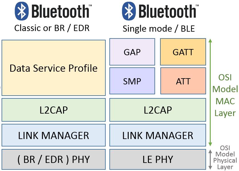
Future Internet 2019, 11, 16                                                                      2 of 42

the development and deployment of each protocol. Therefore, the study of MAC layer protocols can
show how to design a suitable technological solution for an application.
     Based on its own needs, IoT applications may require the adaptation of the existing network
protocols so that they can meet the requirements of IoT applications. Protocols may need to be
adjusted, evolved or developed to meet the IoT applications that demand different performance
characteristics such as far-reaching, reliable and robust low power transmission techniques. According
to requirements, it is possible to classify and point out the main MAC layer protocols suitable to
attend a service characteristic. The already existing definitions such as Wireless Body Area Networks
(WBAN), Wireless Personal Area Networks (WPAN), Low Rate Wireless Personal Area Networks
(LR-WPAN), and Wireless Local Area Networks (WLAN) can be classified as short distance protocols
due to their maximum range of 1 km. While Wide Area Networks (WAN) and Low Power Wide Area
Networks (LP-WAN) protocols can be used as references for long range classification due their ranges
of more than 1 km. WAN protocols are commonly designed for user content and the media. Some of
their evolution such as Long Term Evolution (LTE) CAT-M have enhancements to support some IoT
requirements such as lower power consumption. LP-WAN protocols came to attend long range with
low power consumption but enough data rate to attend IoT services requirements.
     The purpose of this paper is to present a deep study of short and long distance MAC layer
protocols used by IoT solutions, addressing the MAC layer characteristics that defines each protocol
behavior and applicability. This approach arises MAC layer comparisons in several aspects, including
distance coverage, transmission data rate, transmission efficiency, communication mechanisms, MAC
and PHY (Physical) layer control techniques, both in terms of use of resources and efficiency aspects of
packet processing among other performance metrics. This study also gives inputs to obtain reference
and comparison parameters in the design or choice of a technology to better serve a certain application,
with specific characteristics. Thus, the main contributions of this paper are the following:

•     Deep review of the state of the art and classification of short and long distance IoT MAC
      layer protocols;
•     Comparison study of the protocols considering their specifications and characteristics;
•     Identification of open research issues and lessons learned on the topic.

     The rest of this paper is organized as follows. Section 2 elaborates on a detailed study of short
range coverage MAC layer protocols. A deep study of long range MAC layer protocols is present in
Section 3. Section 4 brings a discussion about short and long distance IoT MAC layer protocols arising
from their main characteristics through comparison identifying a set of important open research issues.
Section 5 gives a summary of the lessons learned is exposed and, finally, Section 6 concludes the study.

2. Short Range MAC Layer Protocols
      Short range coverage medium access control (MAC) protocols are defined by the Institute of
Electrical and Electronics Engineers (IEEE) as Wireless Personal Area Networks (WPAN), which is
the network established between elements that surround the human body. WPAN communication
technologies differ from other conventional wireless network technologies. These networks call for
easy connectivity in order to reach personal wearable or hand-held devices. Moreover, WPAN requires
power efficiency, small size, low cost and maybe most importantly easy to use devices [2,3].
      Short-distance technologies such as near field communication (NFC) and radio frequency
identification (RFID) are technologies that fit into this study context due to their usage with
differentiated mechanisms for the physical and linking layers. Thus, their characteristics are less
critical when compared to the IEEE 802.15.6 standard [4], which is dedicated to wireless body area
networks (WBAN). Such networks have different scenarios and prerequisites that are very different
from those that are supported by the networks of things. Body sensor networks have very critical
requirements when compared to the networks of things such as WBANs. These network characteristics
should achieve a maximum latency of 125 ms to attend medical applications, they cannot surpass
Future Internet 2019, 11, 16 3 of 42
250 ms to be applied to non-medical applications, and their jitter must be lower than 50 ms. Low
power consumption, automatic connection and disconnection of new elements in the network, mixed
typologies, low overhead and other characteristics are examples of the high critical parameters in
WBANs [5–7].
There are technologies that use differentiated methods to treat their PHY and MAC layers as
Long Term Evolution (LTE) mobile networks. These technologies offer differentiated techniques of
connection establishment methods, communication controls, and physical access controls, among
others. Thus, it becomes difficult to compare some protocols with the standard offered by the open
systems interconnection (OSI) reference model. The physical medium approach and connection
establishment methods, communication controls, and other mechanisms are dedicated to systems that
cannot be directly compared to the OSI. Another difficulty of establishing a fair comparison with other
protocols that follow the OSI reference model is that these protocols are, in the majority of applications,
dedicated to the point-to-point communication or large data volumes. These characteristics release
them from the need for more elaborate connection establishment methods and data transfer control
systems [8].
2.1. Radio Frequency Identification (RFID)
Radio Frequency Identification (RFID) refers to a set of technologies that are aimed at identifying
and recognizing elements (tags). An RFID system is basically composed of two types of devices:
the identified devices (tags) and the device identifiers or readers. Tagged devices are triggered by RF
(Radio Frequency) waves emitted by the reader devices and reply its identification (ID) tags. Readers
handle data exchange between them. When necessary, readers send RF pulses interrogating the
tags in the area. Tags reply to this question by submitting their tag IDs. Different classifications of
RFID systems can be provided according to operating frequency, radio interface, communication
range, tag autonomy (completely passive, semi-passive, active), and different standards have been
ratified. Evolution of smart UHF (Ultra High Frequencies) RFID tags with embedded sensors
and miniaturization of readers promotes this technology for high pervasive IoT ecosystems [9].
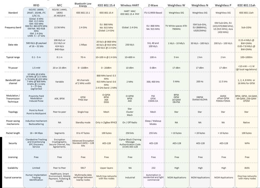
Figure 1 presents a brief summary of operation frequencies, transmission power level, and European
regulation comments.
Figure 1. RFID standards for short distance applications [10].Future Internet 2019, 11, 16 4 of 42
The various devices identified by radio frequencies (RFIDs) such as wristbands, clothing,
footwear, and others are a combination of a small microchip and an antenna integrated into a single
casing uniquely identified electronically. When readers send their interrogation radio frequency
pulse, tags transmit their identification information to the reader devices using radio frequencies.
This transmission takes place depending on the proximity of the tag to the reader device, even though
it does not have line of sight (LOS). The transmission range will depend on the class of device used.
Transmissions occur from the low frequency (LF) bands at 124–135 KHz to ultra-high frequency band
(UHF). There are three classes of RFID devices [11] as follows:
• PRAT—Passive Reader Active Tag. The reader is passive and receives data from a battery-powered
tag. The transmission range can reach up to 500 m depending on some characteristics of the
system and transmission frequency used.
• ARPT—Active Reader Passive Tag. The reader is active and the identified tags are passive and
powered by the energy harvested from the electromagnetic waves present in the air. In general,
this power source can be a beacon transmitted by the reader to feed the tags and it receives back
the transmission of the tag data. This is the most commonly used class.
• ARAT—Active Reader Active Tag. This class is where both the reader and the tags are powered
by external power sources, but the tags only transmit their data when requested by the readers.
There is a certain variety of standards for RFID systems. ISO (International Organization
for Standardization)/IEC (International Electrotechnical Commission) 14443 [12] are the entities
responsible for defining the behavior and properties of smart cards [13,14]. The standard defines the
nomenclature of the ’reader device’ as the Proximity Coupling Device (PCD) and the Tag Identified
(TI) or, ‘the object to be identified’, is defined as the Proximity Integrated Circuit Card (PICC).
One of the most commonly used identification standards in this case is the electronic product code
(EPC) which contains a 96-bit structure in a string data format. This structure consists of eight initial
bits that identify the protocol version followed by 28 bits representing the organization entity that
produced such a label. The following 24 bits identify the type or class of the element and the remaining
36 bits are the unique serial identification of each particular element. These last two fields are used by
vendors to assign identities to their devices [15]. Differentiated information such as Uniform Resource
Locators (URLs) or some other more current pattern can also be used as identifiers as long as they
meet the standardized format [16,17].
2.2. Near Field Communication (NFC)
For short-range communications, NFC technology is important since its massive adoption by
mobile device vendors has popularized its use, making it accessible to the public for applications
such as label reading or even peer-to-peer data exchange. The devices involved exchange information
between themselves as a machine-to-machine connection mode [18]. Standardization of NFC is
assisted by the International Organization for Standardization (ISO) conjoined with the International
Electrotechnical Commission (IEC) and NFC Forum.
Near Field Communication is a short range transmission technology that uses low-power
transmission links that, differently from Bluetooth, do not require pairing for transmission. Just
bringing one device close enough to the other allows communication. This feature forces the user of
the device to be handling it during use. As the facility of the device works only with is owner, it is
a manner to ensure the safe security of the technology usage. Its operation is comparable to RFID
technology because NFC devices can act as both a reader and a tag. The communication is performed
in active or passive mode, operating in the 13.56 MHz band. A typical range from another device is
about 0.2 m and it is sensitive to near fields or even the touch, its transmission rate can reach 424 Kbps.
In the passive mode communication, the active device initiates the connection by transmitting a carrier
wave that activates the passive device. Thus, the passive device makes use of this carrier to modulate
and transmit its data. In the active mode of communication, both the communication initiating deviceFuture Internet 2019, 11, 16 5 of 42
and the target device communicate by generating their own carrier waves. These devices need to be
powered by external power sources.
NFC tags and readers can operate in three different modes: card emulation, reader/writer and
peer to peer (or point to point). In NFC Card Emulation mode, usually the active device reads the
passive device tag types. Both of them can be active or passive devices. In the NFC Peer to Peer (Point
to Point) mode standardized according to the ISO/IEC 18092 [19], two nodes are connected to each
other by a peer to peer or ad hoc mode in order to exchange data [20]. The massive deployment of
NFC came to join the use of RFID as complementary technology and, as a consequence, are becoming
important technological solutions for pay-machines, smart objects, smart wearables, and many other
devices. These technologies are commonly used in applications, such as tracking objects and people,
to offer personalized information and services such as in e-health applications. This scenario brings
a new concept of “thing” or object socialization. In this concept, the link between the ported object
and the person who carries it establishes a unique co-ownership and relationship. This relationship
is capable of influencing decisions in human environment interactions and raising the level of the
consciousness of the object [21,22].
On the physical layer of NFC, RF communication data rates are 106, 212, 424 as well as 848 Kbps
depending on the combination of modulation and code techniques used. The available modulation
schemes are ASK (Amplitude Shift Keying) using 10% or 100% modulation depth, Non-Return-to-Zero
Level (NRZ-L), Binary Phase Shift Keying (BPSK) and Manchester or Modified Miller coding are
used for the data transfer. The International Organization for Standardization (ISO), International
Electrotechnical Commission (IEC), and Federal Communications Commission (FCC) regulate the
transmission power to be 20 or 23 dBm according to region [23–26]. The NFC MAC layer is
also responsible for connection handling, message exchange, emulation modes, anti-collision bit
transmission, activation procedures, data transport, and others. Figures 2 and 3 illustrate these
functionalities [18].
Figure 2. NFC passive to active device communication protocol stack.Future Internet 2019, 11, 16 6 of 42
Figure 3. NFC active to passive device communication protocol stack.
2.3. Bluetooth IEEE 802.15.1
WPAN IEEE 802.15.1 also called the Bluetooth Basic Rate (BR) is a global 2.4 GHz specification
working with short-range wireless networking. It covers the versions v1.0, 1.0B with voice dialing, call
mute, last number redial and a 10 m range as the main facilities and a v1.2 with adaptive frequency
hopping added. Versions v2.0+Enhanced Data Rates (EDR) and v2.1+EDR added more capabilities
such as improved resistance to radio frequency interference as well as improving indoor coverage and
LOS range to 100 m. Fast transmission speeds and low power consumption mechanisms were also
increased on the v2.0+EDR and v2.1+EDR versions. Version v2.1 counts on a sniff subtracting function
that results in less transmissions do access the medium and so reducing interference.
The evolution follows with v3.0 receiving enhanced power control to quickly adapt to the changing
path loss of the new 5 GHz transmission frequency bands. Version 4.0 increased the modulation index,
resulting in less energy used during transmission but still presented a certain medium consumption
to complete the receiving process. Version 4.1 shows better alignment on pico-nets timing when the
transmission suffers interference. In Version 4.2, the low energy is reinforced with the adoption of
longer packet transmissions. This reduces the quantity of packets transmitted for the same information
size, using a packet length extension technique. The present version of Bluetooth v5.0 has some
improvements regarding transmission and receiving processes. The Bluetooth v5.0 improvements
include slot availability mask, which allows the alignment of pico-nets timing with nearby LTE bands,
an increased coding gain, increased symbol rate and a better channel selection algorithm.
The IEEE 802.15.1 MAC layer is composed of Logical Link Control, the Adaptation Protocol
(L2CAP) layer, the Link Manager Protocol (LMP) layer, and the Base-band or simply the Physical
layer. The Bluetooth MAC layer handles the communication types that can be asynchronous
connectionless (ACL) or synchronous connection-oriented communication (SCO). Figure 4 shows the
relationship between the Open Systems Interconnection model (OSI), the seven-layer model and the
IEEE 802.15.1 standard.
Figure 4. Mapping of OSI reference model to IEEE 802.15.1 Bluetooth stack.Future Internet 2019, 11, 16 7 of 42
The Base-band Layer defined by the IEEE 802.15.1 standard operates in the 2.4-GHz Industrial
Scientific and Medical (ISM) band using a short-range radio link and a fast frequency-hopping (FFH)
transceiver. The Radio and the Base-band sub-layers define the Bluetooth physical layer. The Radio
layer provides the physical links among Bluetooth devices with 79 different Radio Frequency (RF)
channels spaced of 1 MHz, using a frequency hopping spread spectrum (FHSS) transmission technique.
This FHSS technique increases the robustness of the link due to its capability to reduce the interference
of nearby systems that may operate in the same frequency range. A Time Division Duplex (TDD)
transmission scheme is specified to divide the channel into time slots of 625 µs each, corresponding to
a different hop frequency, simulating full-duplex communication in the same transmission channel.
The radio link which reaches up to 100 m with LOS is obtained using the nominal power according
to its power class and the irradiating system used. Three output power classes divide the Bluetooth
Basis Rate protocol devices. Each class is characterized by a maximum power and a minimum output
power, and, based on these values, the distance within which the device can communicate is defined
according to the list in Figure 5.
Figure 5. Bluetooth power class classification.
The main roles of the Bluetooth MAC layer are to set-up the physical connections between the
master and slaves; send and receive packets along the physical channels; synchronize the network
devices with the master clock and manage the different devices for power saving states [27].
In summary, the base-band functionalities are clock synchronism, management timers, addressing
and assessment devices, physical channel handling, channel hop selection, physical link supervision,
logical transport management, logical link management, formatting and ordering bits, bit-stream
processing, error checking, error correction, definition of ARQ (Automatic Repeat Request) schemes,
managing link controller operations, support for general audio recommendations, audio level control,
audio paths, frequency mask, and others.
A Link Management Protocol is a control protocol responsible to establish base-band and
physical layer links. Functions such as connection establishment and release, among others,
are Link Management (LM) features acquired by LMP utilization that handles a Synchronous
Connection-Oriented (SCO) link, and an Asynchronous Connectionless Link (ACL). A SCO physical
link establishment is a symmetric point-to-point connection between the master and a specific slave.
It is used to deliver delay-sensitive traffic, such as voice service, and works as a circuit-switched
connection between the master and the slave. The ACL link is a point (master) to multi-point (slaves)
in a pico-net domain and works as a packet-switched connection, which considers the Bluetooth
devices that support point-to-multi-point connections. To ensure the integrity of the data and to
guarantee a reliable delivery of the data, ACL uses a fast Automatic Repeat Request scheme.
The Logical Link Control and Adaptation Protocol (L2CAP) layer is a channel-based abstraction
between the base-band and service application layer. The L2CAP layer handles segmentation and
reassembly of application data, and multiplexing and de-multiplexing of multiple channels over
a shared logical link [28]. The L2CAP layer is responsible for handling the size adjustment of the
maximum transmission unit (MTU) when the application layer data is larger than the MTU of the
base-band layer. The L2CAP layer can segment the application data in order to seize the maximum
MTU transmitted based on the size of the MTUs received by the application This feature reduces the
overhead on the information sent thus, improving the efficiency. Endpoint peer devices receive a
Channel Identifier (CID) used for signaling purposes associated to its connections, for ACL and SCOFuture Internet 2019, 11, 16 8 of 42
data communication between L2CAP devices. Some CIDs are reserved for the L2CAP layer as a logical
channel required to meet Bluetooth standards and is reserved for signaling purposes. Connectionless
channels support ‘group’ or multi-point communication, while connection-oriented channels are
dedicated to peer-to-peer connections only [29]. Figure 6 elucidates the data channelization, links and
transport structure.
Figure 6. Bluetooth data link structure.
Bluetooth relies on the contention-free token-based multi-access networks as logical topology.
End point devices are mentioned as slaves. A cluster of up to seven slave devices can be attached
to a master device, in order to have access to the channel, composing a pico-net cellular topology.
The master is responsible to manage the polling process messages to authorize a slave device to
access the channel and transmit its data. These features increase the range to more than 100 m with
a LOS path in an outdoor environment also increasing its indoor environment range to about 40 m.
The utilization of beacons as sense mechanisms and the larger message capacity of 255 bytes improves
the communication performance.
Data rates have a theoretical value of 2 Mbps but with a practical recommendation of 1.6 Mbps
considering overheads. A pico-net data rate can reach up to 1 Mbps, which represents the channel
capacity not considering the overhead introduced by the adopted access control techniques and polling
scheme. The coverage areas of the pico-nets can be overlapped forming a scatter-net topology when
at least one unit exchanges data with more than one master. This allows a slave to be active in more
than one pico-net at the same time but can be managed by only one master element. When using a
time-multiplexing mode, a slave can communicate with more than one pico-net but only in different
time periods. This is due to the necessity to change its synchronization parameters or in order to listen
to different channels. A size of a pico-net is limited to just one master and up to seven active slave
stations [27]. The conventional ad hoc topology is also used.
2.4. Bluetooth Low Energy
Being part of the Bluetooth v4.0 standard adopted in 2010-06-30, Bluetooth Low Energy (BLE)
is also known as Smart Bluetooth. BLE is an IEEE 802.15.1 variation with better and more suitable
capacities for low power applications than the classic Bluetooth Basic Rate. Devices that demand
communication with both standards of Bluetooth are required to implement and support both protocol
stacks due the incompatibilities among them. Star is the only topology accepted by BLE due the
standard definition that does not permit physical link connections among slave devices. Any data
exchanged between two slave devices shall pass through the unique master and a slave device may
not be connected to two master units at the same time. These premises define the formation of a BLE
star pico-net [30].Future Internet 2019, 11, 16 9 of 42
Using a similar protocol stack as classic Bluetooth, the differences between them starts above the
L2CAP layer. Above the L2CAP layer, BLE is the application layer that uses a set of functionalities,
which are not present in the classic Bluetooth specifications. These functionalities are the Attribute
Protocol (ATT), the Generic Attribute Profile (GATT), the Security Manager Protocol (SMP) and the
Generic Access Profile (GAP). Figure 7 depicts the BLE protocol stack.
The two main roles of BLE are: controller and host. BLE differs from the classical Bluetooth in the
controller stack that defines the association methods of the devices. A slave can belong to only one
pico-net during an association lifetime, and is synchronized with only one master element.
A Host Controller Interface (HCI) is a communication standard applied between the slave and
controller. In the Bluetooth Basic Rate, 79 channels are used with a 1 MHz bandwidth to reduce
interference with adjacent channels. In Bluetooth Low Energy, the channels are defined in the
2.400–2.4835 GHz band with a 2 MHz guard band. To achieve scalability, the master device controls
the number of hosts associated with it by adjusting the value of the connection interval (ConnInterval
parameter) between hosts and controllers.
Figure 7. Bluetooth low energy protocol stack.
Link layer manages events generated by the hosts, at determined time intervals, using the
advertising channels. Bidirectional data flow is obtained with a connection between elements,
when slaves advertising packets are received by master elements. The energy save handling done at
MAC layer can put the slaves in a sleeping mode by default and waking them periodically through
a Time Division Multiple Access (TDMA) scheme. In the classic Bluetooth basic protocol, this layer
a stop-and-wait flow control mechanism is used to provide error recovery capabilities. At BLE, the
L2CAP is an adaption of the classic Bluetooth basic protocol stack but optimized and simplified
to receive the application layers designed for low energy platforms. Data exchange between the
application layer and link layer are also done by L2CAP using no retransmission techniques or
flow control mechanisms as used on the classic Bluetooth. Not using retransmission or flow control
mechanisms (present in the classic Bluetooth) and segmentation and reassembly capabilities, the Packet
Data Units (PDU) (limited to 23 bytes in BLE) received by the application layer is delivered ready to fit
the maximum size of the L2CAP payload.
When two devices are connected under a server and client association architecture, the server
needs to maintain a set of attributes. The Attribute Protocol (ATT) handles the attributes of this
connection like the definition of data structure used to store the information managed by the Generic
Attribute Profile (GATT) that works on top of the ATT. GATT defines the client or server functionalities
of a connection and this association is independent of the master or slave roles. The attributes of the
server need to be accessed by the client through the requests sent, which trigger the response messages
of the server. It is also possible for a server to send to a client, unsolicited messages like notificationsFuture Internet 2019, 11, 16 10 of 42
that do not need any confirmation message to be sent by the client. A server is also required to send
indication messages, which need confirmation messages to be sent by the client. The slave sends
requests for responses and indications prior to transactions confirmation following a stop-and-wait
scheme. Slaves can either write attributes values at the master.
A framework defined by GATT performs the role of discovery services using the ATT attributes,
and allows exchange of characteristics between devices interconnected. An attribute carries a set
of characteristics that includes a value and properties of the parameter monitored by the device.
For example, a humidity sensor needs humidity characteristics and attributes to describe this
sensor, and to store its measurements. Thus, this sensor needs a further attribute to specify the
measurement units.
Creating specific profiles with the Low Energy Bluetooth standard takes place in the Generic
Attribute Profile (GATT). GATT uses the Attribute Protocol (ATT) protocol in addition to the lower
stack protocols, in order to introduce the subdivision of retained server attributes into services and
features. Services can contain a set of features, which can include a single value (accessible from the
client) and other numerical data that describe such features. Among the assignments of GAP profile
specifications are: device role rights, discovery devices and services, as well as establishing connections
and security. A new profile based on the existing profile requirements can be created following a
profile hierarchy. The interoperability of different devices can be handled through application profiles.
Bluetooth is designed to offer a low-cost alternative to Wi-Fi at the expense of the transmission
range. Its transmission range is considerably shorter (up to 100 m LOS) and data rate does not exceed
721.2 Kbps in the classic Bluetooth Basic Rate version and can reach 3 Mbps with the Enhanced Data
Rate feature. BLE operates at 1Mbps rate on its physical layer, while its application layer can handle
only 236.7 Kbps.
In Bluetooth Low Energy, there are no subdivisions in power classes but only the maximum and
minimum output power values of the transmitter are provided. Only an approximate value of the
maximum reachable distance can be predicted. The low power required for transmission is the main
feature of the Bluetooth Low Energy standard and this result is due to enhancements made on the
classic version. These enhancements include reduced frequency band and shorter PDU packets [31].
An energy evaluation is offered at [32] using CC2640 radio chipset consumption reference
measurements. The comparison is made when operating on 0 dBm transmission power by gathering
the main characteristics of Bluetooth and BLE.
Bluetooth v5.0 has no functional block included in its first and second layers when compared
to versions v4.0, v4.1, and v4.2. A representation of the inter-layer communication structure and
the relationship with Bluetooth layers of different Bluetooth versions can be seen in Figure 8.
Device-to-device file transfers, wireless speakers, wireless headsets, and Body Sensor Networks
are often enabled with Bluetooth versions.
Finally, some characteristics of the Bluetooth BR and BLE technologies are summarized in
Figure 9. This figure allows the comparison of their differences according to the PHY and MAC
layer characteristics.
Figure 8. Bluetooth power class classification.Future Internet 2019, 11, 16 11 of 42
Figure 9. Bluetooth basic rate versus Bluetooth low energy.
2.5. IEEE 802.15.4
IEEE 802.15.4 is a subgroup of features that refers to physical and medium access control layers
that can support ZigBee and 6LoWPAN upper. IEEE 802.15.4 focuses on physical and data link layer
specifications while ZigBee Alliance aims to provide the upper characteristics [33]. It is a standard
that defines PHY and MAC layers for personal area networks that demand low rate and low cost
applications. This also called a LR-WPAN protocol and has some advantages. Among them are a
simple and flexible protocol stack, low cost, low energy consumption, short-range operation, reliable
data transfer, and ease of operation [34]. These features are more important when operating in the
Personal Operating Space (POS) also defined as Personal Area Network (PAN) that involves the
human body.
An IEEE 802.15.4 device address can be a short 16-bit or 64-bit address [35]. In addition, IEEE
802.15.4 uses a Direct Sequence Spread Spectrum (DSSS) access mode and operates on 2450 MHz,
915 MHz, and 868 MHz ISM bands working with 16 channels, 10 channels, and one channel,
respectively. The main limitations of the radio interfaces working in the ISM frequency band are
the small sizes and the narrow bandwidths. Small sizes and narrow bandwidths consequently cause
a reduction in output power transmission. With these radio interface characteristics, it is possible to
obtain from 20 to 250 Kbps shared among all the nodes using the same channel [36,37].
The physical layer provides an interface between the physical data service and the PHY
management service accessed through service access points (SAPs). This layer is also responsible
for activation, and deactivation of the radio transceiver, energy detection (ED) within the current
channel, link quality indication (LQI) for received packets, clear channel assessment (CCA) for carrier
sense multiple access with collision avoidance (CSMA-CA), channel frequency selection, and data
transmission and reception. The energy saving aspects of IEEE 802.15.4 are mainly addressed to
this layer by the ED, LQI and CCA functionalities [35]. According to the PHY layer specifications,
and following the spectrum utilization of each region, the distances between the nodes based on
IEEE 802.15.4 can be up to 100 m. This range depends on propagation environment obstacles
and the maximum transmission power levels defined by the IEEE 802.15.4 standard, illustrated
in Figure 10 [3,38].
The IEEE 802.15.4 MAC layer provides access to the physical channel for all upper layers, providing
two kinds of services: the MAC data service and the MAC management service. MAC data and MAC
management are services that are also provided to other layers enabling them to access the PHY layerFuture Internet 2019, 11, 16 12 of 42
resources. The standard defines two different methods of channel access that are a beacon enabled (BE)
mode and a non-beacon-enabled (NBE) mode. The MAC sub-layer, which is responsible for beacon
management, is also responsible for channel access, Guaranteed Time Slots (GTS) management, frame
validation, delivered frame acknowledgement, and association/disassociation activities [33].
An IEEE 802.2 Logical Link Control (LLC) can access the IEEE 802.15.4 MAC sub-layer through
the Service Specific Convergence Sub-layer (SSCS). The SSCS IEEE 802.2 convergence sub-layer exists
in a conceptual perspective, on the top of the MCPS (MAC Common Part Sub-layer). SSCS provides
a link between the IEEE 802.2 LLC sub-layer and the IEEE 802.15.4 MCPS in the data service plane
through the MCPS-SAP (MCPS-Service Access Point). On the management plane, driving the layer
management functions, the MMLE (MAC sub-layer Management Entity) provides the service functions
assembling capability through an interface between the SSCS and PHY. MMLE is also responsible
for maintaining a PIB (PAN Information Base) which contains the data base of the managed objects
belonging to the MAC sub-layer [3].
Figure 10. IEEE 802.15.4 maximum transmission power levels according to regions.
The IEEE 802.15.4 BE and NBE operational modes have being strongly investigated over recent
years. Thus, some limitations have been addressed and the most important ones are the unbounded
delay, low communication efficiency, low interference robustness, and/or fading and main powered
relay nodes [39–43].
The IEEE 802.15.4 Task Group 4e was chartered to define a MAC amendment to the standard
802.15.4-2006 in order to evolve and add important functions to the 802.15.4-206 MAC protocol to
enhance MAC to PHY functionalities interaction [44]. IEEE 802.15.4e supports five new categories
of MAC enhancements also called MAC behaviors: Time Slotted Channel Hopping (TSCH),
Deterministic and Synchronous Multi-channel Extension (DSME), Low Latency Deterministic Network
(LLDN), Asynchronous Multi-channel Adaptation (AMCA), and Radio Frequency Blink (BLINK) [45].
Some general enhancements were also included as follows: Low Energy (LE), Information Elements
(IE), Enhanced Beacons (EB), Multipurpose Frame, MAC Performance Metrics, and Fast Association
(FastA) mechanism [46]. Figure 11 compares IEEE 802.15.4 stack with the OSI reference model.
Figure 11. IEEE 802.15.4 compared with OSI reference model.Future Internet 2019, 11, 16 13 of 42
The use of multipurpose sensor networks becomes as a natural network environment with a
focus on how to reduce the implementation of the operation costs through the reuse of resources.
Ordinary traffic generated by regular applications such as environmental monitoring will not require
the same treatment as the traffic response required for applications that use information queries
time sensitive [47] characteristics. A heterogeneous traffic coexistence, with different QoS (Quality of
Service) requirements is not handled well by IEEE 802.15.4. One option to improve QoS is the adoption
of multiple transmission queues in both 802.15.4 and 802.15.4e considering the urgency level of the
different traffic. This process separates the different QoS traffic in different classes and handles them
on four transport queues with differential treatments [36,48] .
Mobility can be treatable by IEEE 802.15.4 but can hardly degrade the network performance [49]
and happens when an orphan device that loses its coordinator association attempts to synchronize
with network coordinators. The IEEE 802.15.4 terminal uses the common transmission channel to
search for coordinators. On the topology aspect, the coordinators that belong to the same Personal
Area Network Identification (PANId) are connected to a Super Coordinator that can handle the device
mobility from one coordinator to another. It is important to point out that, during this re-association,
the service data are interrupted. Some authors enlarged their visions beyond IEEE 802.15.4 limits
suggesting inter-technology mobility. For example, to allow a mobile node to move through the
cells in a various cluster tree network. Coordinators have both IEEE 802.15.4 wireless and wired
connections” [50] to expand the mobility domain. Energy performance is boosted by channel hopping
based on multi-channel support. The development of IEEE 802.15.4 is a joint work between IEEE and
ZigBee Alliance. The stack consists of layers one and two of the IEEE 802.15.4 standard as the basis for
other protocols such as ZigBee itself, 6LoWPAN, Thread, and ISA100 [51,52]. Due the fact that these
protocols are derived from the IEEE 802.15.4 PHY and MAC layers, they belong to the network layer
and are out of context for this comparison.
2.6. Wireless-HART
Wireless-HART (Highway Addressable Remote Transducer Protocol) is a variation of IEEE
802.15.4 design to work essentially as a centralized wireless network. IEEE 802.15.4 is designed to meet
the requirements of industrial wireless applications with hard timing parameter restrictions, critically
security issues, and severity on obstacle interferences. The Wireless-HART protocol has the same
specifications as IEEE 802.15.4 PHY, but develops its own MAC layer based on the TDMA technique.
Using Bluetooth, there is no guarantee to delay values on an end-to-end wireless communication.
The absence of a hopping channel technique and a quasi-static star Bluetooth topology works against
its scalability. These characteristics make them inappropriate to be used in industrial scenarios.
Wireless HART comes as a solution for process control applications through the effort of some
industrial organizations such as International Society of Automation 100 (ISA 100) [52], HART [53],
Wireless Industrial Networking Alliance (WINA) [54] and ZigBee Alliance [55] to attend their specific
requirements ratified by the HART Communication Foundation in 2007.
Using the IEEE 802.15.4 PHY layer, Wireless-HART operates in the license-free ISM of
2.4–2.4835 GHz with 2 MHz bandwidth of each one of the 16 channels. The channels are numbered
from 11 to 26 with a gap of 5 MHz between IEEE 802.11b/g adjacent channels, delivering up to
250 Kbps. Wireless-HART uses its own Time Division Multiplex Access (TDMA) on the MAC layer
including the 10 ms synchronized time slot features. These characteristics allow the messages routing
through a network topology obstacle and interference. This is possible due to the use of self-organizing
and self-healing mesh networking techniques supported by the network layer. Even being essentially
a centralized wireless network, Wireless-HART uses a network manager in its stack in order to provide
routing and communication schedules. This can guarantee network performance and satisfy the
wireless industrial applications. The focus of Wireless-HART is communication on a one-hop level
and the network layer has its responsibility to the network devices vicinity allocation [3,56–58].Future Internet 2019, 11, 16 14 of 42
Differing from IEEE 802.15.4, Wireless-HART uses time-synchronized the TDMA technique
combined with frequency hopping on its MAC layer, thus allowing multiple devices to
transmit data at the same time along different channels. During the joining process of the
devices onto networks, the network manager distributes the communication links and the
channel hop patterns to the devices. It also manages the enabling or disabling of the use
of channels that are frequently affected by considerable interference levels, calling this feature
channels blacklist,wHart-n-802-15-4e,petersen2011wirelesshart. The eight types of devices defined on
Wireless-HART are: routers, gateways, adapters, network managers, network security devices, access
points and field devices on a mesh topology. All of them support the implementation of features to
attend network creation, maintenance issues, data and signaling routing capability, and a minimum of
reliability. A comparison between the OSI reference model and Wireless-HART protocol layers and its
main features is shown in Figure 12.
Figure 12. WirelessHART Protocol Stack.
Another addressable characteristic of Wireless-HART is the information blocks that each network
device maintains on its memory. The information of neighbor nodes and the next reachable device
is called a neighbor information block. The connection with the network layer is made through the
block information, adding data to the network layer routing table. Working with TDMA as a medium
access technique, the network devices have very stringent timing requirements to accomplish network
synchronization premises. This happens because synchronization occurs both in the joining process
and in normal operations [58].
2.7. Z-Wave
Z-Wave was developed and is overseen by the company Zensys to provide wireless
communication between devices with a focus on residential automation. Monitoring and controlling
of lighting, ambient temperature and security through sensors and actuators by tablets, smartphones
or computers are some applications in its portfolio. Z-Wave devices are arranged in mesh network
topology. They can send and receive messages from any device that is connected to the network [59,60].
The protocol is a proprietary standard based on the ITU G.9959 specification that operates in
the Industrial, Scientific, and Medical (ISM) radio frequency band. Z-Wave transmits on 868.42 MHz
(Europe) and 908.42 MHz (United States) frequencies working with FSK and Gaussian Fase Shift Keying
(GFSK) modulations. With low transmission rates of 9.6 Kbps, 40 Kbps and 100 Kbps, it employs
symmetric AES-128 encryption. The MAC layer uses the CSMA-CA technique for a medium accessFuture Internet 2019, 11, 16 15 of 42
control technique and, based on ITU G.9959, has the following characteristics: a capacity of 232 unique
network identifiers that allows the same quantity of nodes joying the network; collision avoidance
mechanism; back-off time when collision occurs; reliability guaranteed by receiving acknowledgments;
frame validation and retransmission mechanisms. A power saving mechanism is achieved due to a
sleep mode with a dedicated wake-up pattern [61,62]. Figure 13 depicts the Z-Wave protocol stack.
Figure 13. Z-Wave protocol stack.
The Z-Wave basic device classes are the following: Portable Controller, Static Controller, Slave,
and Slave with Routing Capabilities. Different classes provide the device with a certain role in the
Z-Wave network. Inside a Basic Class, Generic and Specific device classes are used to achieve the
wanted functionality in the control network. In the Z-Wave protocol, the unique identification of the
devices is used through a 32-bit ID. This ID value cannot be changed as it is written in the device
chipset by the device manufacturer. A Z-Wave network has only one primary controller device at a
time. Each of the 232 nodes of this network can also be a repeater for forwarding data to its neighbors,
mediating a connection. Battery-powered nodes do not enjoy this facility. In an environment with
a certain level of device drift or even when a device is removed from the network for some reason,
the network topology may change. Changing network topology can lead to problems in packet
forwarding and packet routing in the network. To minimize this effect, routing tables should be kept
up-to-date, optimized and any new topology detected; Z-Wave supports the discovery and suitability
of the new network topology. This is possible by keeping the routing table up-to-date on each device
and showing all neighboring devices [61,63]. When a node changes its position or is removed from
the network, a topology failure can start an automatic topology and healing procedure to detect the
new topology and define the best routes to update the routing tables. This mechanism is subjected to
unauthorized modification of routing table attacks by rouge nodes [64].
The transfer (or transport) layer management functions are: communication between two neighbor
nodes, packet acknowledgment, low power network nodes awake (Beaming), and packet origin
authentication. This layer controls the Beam frames used to wake-up battery powered Z-Wave devices,
as each primary controller device of a cluster can handle up to 232 nodes. All nodes can act as a packet
repeater, except those devices that are batteries powered. This is Z-Wave mesh topology formed [65].
Z-Wave data security is based on AES and on the cipher block chaining message authentication
code (CBC-MAC). However, standards and rules for command classes, device types and timers
are missing. These characteristics are only acquired in the new advanced security framework (S2)
determined by the Z-Wave Alliance and developed in conjunction with the cyber security community.
For the certification of new products as of 2017, Z-Wave brings devices a higher level of security.
The structure of S2 is based on the protection of the devices that is already associated with the network,
so they are not hacked while still connected to the network. Once the device has already been associated
to the network through its pin-code or QR (Quick Response) code, there is an exchange of security
keys through the Elliptic Curve Diffie-Hellman (ECDH) algorithm [63,66].Future Internet 2019, 11, 16 16 of 42
2.8. Weightless
Weightless is the name of a set of LP-WAN protocols for wireless communication networks
with low transmission rates. In this set, Weightless have the variations Weightless-P, Weightless-N
and Weightless-W. These technologies are standardized by the Weightless Special Interest Group
(Weightless SIG) [67]. The Weightless network is a typical star topology system composed of the end
devices (ED) and the base stations (BS). EDs are the sensor nodes or are also called leaf nodes and the
base stations (BS) concentrate the communication with EDs. The interconnection with the base stations
composes the base station networks (BSN) that, among other things, manages the system facilities
such as authentication, roaming and radio resource allocation and scheduling.
The physical layer of the Weightless protocol has one variant for high data rates and another
for low data rates. In both cases, the functional blocks that compose the physical layer for
downlink are Forward Error Correction (FEC) encoding, interleaving, whitening, Phase Shift Keying
(PSK)/Quadrature Amplitude Modulation (QAM) modulation types control, spreading factor used,
cyclic prefix insertion, sync insertion and Root Raised Cosine (RRC) pulse shaping. The combination
of the modulation type, FEC rates and spreading factor parameters used impacts the final transmission
rate. This transmission rate can vary from 125 Kbps to 16 Mbps. The data rate of 125 Kbps is
through a modulation of (π/2) BPSK with an FEC rate and spectral scattering. In addition, 16 Mbps
is achieved when the modulation used is 16-QAM without the use of the FEC mechanism and the
scattering factor spectral is reduced. Depending on the availability of FEC encoder module, the
interleaving module may be present or not. When present, the interleaving block provides time
diversity and increases the robustness of the process adding a processing gain. The whitening module
uses a known random sequence to scrambler the bit stream turning it into a pseudo white noise,
and increasing the receiver synchronization performance. A spreading module is necessary to spread
the modulated data that receives a cyclic prefix insertion, in order to reduce the multi-path transmission
effects. This characteristic adjusts the frame conversion from the time domain to frequency domain.
The synchronization pattern necessary to receive processes is then inserted by the sync insertion
module. The RRC pulse shaping acts as a digital filter to reduce the radiation that surpasses the
transmission radio frequency band. On the receiving process, appended modules are necessary to
coarsen the time offset estimation and correction. It is necessary to find out the start of the burst,
the fine frequency offset estimation and correction, channel estimation and equalization and timing
detection to determine payload start position.
Like many other systems, Weightless uses channels to exchange data between the protocol layers.
They are classified according to their role as control channels, logical channels transport channels,
and physical channels. To allow base-band data exchange, the Physical layer (PHY) has three physical
channels. They are named the downlink channel, uplink channel and uplink contended access
channel. To transmit data from the base station to one or multiple EDs, the downlink channel is used.
To uplink communication, from an ED to the access point, the uplink channel is used. The uplink
contended access physical channel is also used to transmit data from the end devices to the base station.
This channel is contended by the end devices and several EDs are allowed to transmit at the same time
using this channel.
A Base-Band (BB) sublayer is responsible for providing the transport channels to transport the
data to or from the Link Layer (LL). This is done by connecting the transport channels to the physical
channels of PHY. Among the operations carried out by BB are identification of structured allocations
within a frame structure and the transmission of the frames in both uplink and downlink directions,
using appropriate physical channels. The Contended Access (CA) procedure is also controlled by BB
using the uplink contended access physical channel. The communication between LL and BB is done
by a set of transport channels and its channels are defined according to the type of information of
addressing that is used. Connecting logical channels to the BB transport channels is the LL. LL is also
responsible for retransmission control, reliability of the logical channels and for data fragmentation and
reassembly. These processes can be either acknowledged or not. The multiplexing and de-multiplexingFuture Internet 2019, 11, 16 17 of 42
processes of the transport channels into logical control or user data channels is done by the LL.
Thus, the LL provides such logical channels to allow the data or control traffic between the end devices
and the BS or a BSN through an acknowledged and reliable or an unacknowledged and unreliable
packet stream.
Radio Resource Manager (RRM) is present to control the traffic between an ED and its BS through
Control Channels, using appropriate security provided by LL. The messages that control and maintain
the connection between the ED and BS during the communication between them, is handled by RRM
through the control channels. RRM also provides a downlink-only control message stream sent by the
BSN, in order to maintain the link between the ED and BS. A Weightless protocol stack drawing can be
seen in Figure 14.
Figure 14. Weightless protocol stack.
Payload data is conducted from an ED and its BS through user channels that provide specific
channels for unicast data, multicast data, interrupt data, and acknowledgement data. While the
unicast user data channel is a bidirectional channel between the ED and the BS, the multicast data
channel is a downlink-only channel. The multicast user data channel is an uplink-only channel.
Weightless-W is a bidirectional communication technology that works on a Television White Space
(TVWS) spectrum of 470–790 MHz. Its multiple access mechanism uses frequency hopping (Frequency
Hopping Multiple Access—FHMA) with Time Division Duplexing (TDD). This can separate and
coordinate the uplink and downlink transmission intervals. The data rates range from 1 Kbps to
10 Mb/s and the battery life is from three up to five years depending on usage. This technology
supports star topology and 128-bit AES encryption in its packets. The packets can carry up to 10 bytes
of payload, but encryption can be implemented end-to-end depending on other mechanisms, such as
the network core. The error correction system is based on a Forward Error Control (FEC) algorithm
not specified by the manufacturer. Channeling is done with 16 to 24 channels of 5 MHz bandwidth,
depending on the frequency of use. The modulation of the channels is adaptive and can reach
high rates at short distances according to the need of the application. The modulation can start
with the Differential Phase Shift Keying (DBPSK) and BPSK for greater distances. Lower rates from
1 Kbps use Quadrature Phase Shift Keying (QPSK) or 16-QAM, reaching peaks of 10 Mbps over short
distances [68–71].
Weightless-N is based on the Weightless-W standard and adapted for smaller distances and lower
energy consumption (batteries last up to 10 years), sacrificing the transmission rate from 30 up to
100 Kbps. Weightless-N does not reach the data rate peaks that the Weightless-W can reach. Unlike
Weightless-W, the Weightless-N is based on an Ultra Narrow Band (UNB) system and operates on the
UHF frequency in the 800–900 MHz ISM band, providing only uplink communication. This system
supports star topology and applies the UNB DBPSK (Differential Phase Shift Keying) modulation toYou can also read