Microstructure and Shear Strength of Novel Aluminum to Steel Resistance Spot Welds - DOI.org
←
→
Page content transcription
If your browser does not render page correctly, please read the page content below
Kang Supplement March 2020.qxp_Layout 1 2/7/20 2:15 PM Page 67
WELDING RESEARCH
SUPPLEMENT TO THE WELDING JOURNAL, MARCH 2020
Sponsored by the American Welding Society
Microstructure and Shear Strength of Novel
Aluminum to Steel Resistance Spot Welds
Multiring domed electrodes produced consistent intermetallic shear strength,
which was directly measured using novel mini-shear specimens
BY J. KANG, L. SHI, B. SHALCHI-AMIRKHIZ, D. R. SIGLER, A. S. HASELHUHN, AND B. E. CARLSON
welding, resistance spot welding (RSW), and adhesive bond-
ABSTRACT ing. Resistance spot welding is particularly attractive because
it can be used to quickly join a number of different alloys with-
Resistance spot welds were produced between dissim-
out the additional cost or complexity of rivets, filler materials,
ilar 1.2-mm-thick wrought aluminum alloy AA6022-T4 and
2.0-mm-thick interstitial free (IF) steel with acceptable or lasers. Resistance spot welding has traditionally been used
joint strength using symmetric and asymmetric electrode to join similar alloys, but it can also be used to join dissimilar
combinations that incorporate a multiring domed (MRD) metals, such as aluminum alloys to steel. Sigler and Carlson
electrode and multiple solidification weld schedules. The (Ref. 1) indicated that spot welding aluminum alloys to steel
focused ion beam and transmission electron microscopy materials have several unique challenges due to the disparate
results indicated the intermetallic layer that was created material properties of the two metals. Aluminum and steel
consisted of two distinct layers, i.e., a needle-like FeAl3 melt at very different temperatures (approximately 600° vs.
adjacent to the AA6022-T4 sheet and a tongue-like Fe2Al5 1500°C, respectively). Thus, the aluminum is molten well be-
adjacent to the IF steel sheet. A new mini-shear test was fore the steel is relatively hot. The aluminum sheet also ex-
developed to directly measure the shear strength of the
hibits an insulating oxide layer that increases the surface con-
intermetallic layer formed at the interface of these welds
produced using symmetric and asymmetric welding elec- tact resistance during spot welding. If these challenges can be
trodes. The results showed the intermetallic layer near the surmounted, the melting and solidification of aluminum adja-
aluminum weld nugget periphery, which is the region criti- cent to steel results in the formation of aluminum-iron inter-
cal for joint strength, had an intermetallic layer less than 2 metallics with potentially weak material properties. These in-
μm thick and an average shear strength of 64 MPa, irre- termetallic layers can be detrimental to the strength of the in-
spective of the welding electrodes used. In addition, the terface and any joint that is formed. For example, Qiu et al.
tensile shear strengths of the aluminum-steel welds were used a cover plate to resistance spot weld cross-tension speci-
greater than comparable aluminum-aluminum resistance mens of AA5052 and cold-rolled steel (Ref. 2). Qiu et al. ob-
spot welds. served the interfacial reaction layer can deteriorate the joint
strength when its thickness exceeds 1.5 m. These joints pro-
KEYWORDS duced an interfacial strength of only approximately 6.5 MPa
(Ref. 2).Arghavani et al. reported a thicker intermetallic layer
• Resistance Spot Weld • Shear Strength • Intermetallic of 5.5 m in spot welds comprised of AA5052 to galvanized
Layer • Microstructure • Mechanical Behavior steel (Ref. 3). In welds comprised of AA5052 to low-carbon
steel, Mortazavi et al. observed the 6-m-thick brittle inter-
Introduction metallic compound (IMC) formed at the interface and acted as
an easy crack propagation path, which contributed to high in-
terfacial fracture susceptibility (Ref. 4).
Multimaterial structures are becoming more commonplace To enable welding of aluminum alloys, an electrode that
in the automotive industry to reduce carbon emissions and disrupts outer surface oxide films and minimizes sheet-
improve fuel economy. Along with these structures come chal- electrode resistance was used, so that sheet-to-sheet resist-
lenges posed by joining dissimilar materials, and particularly ance is dominant. Sigler et al. developed a specialized elec-
in joining aluminum alloys to steel materials. trode with a series of concentric rings on a domed surface,
There are numerous ways to join automotive body struc- thus the name multiring domed (MRD) electrode (Refs.
tures, including self-pierce riveting, friction stir welding, laser 5–7). For welding of aluminum alloys to steel materials,
https://doi.org/10.29391/2020.99.007
MARCH 2020 / WELDING JOURNAL 67-s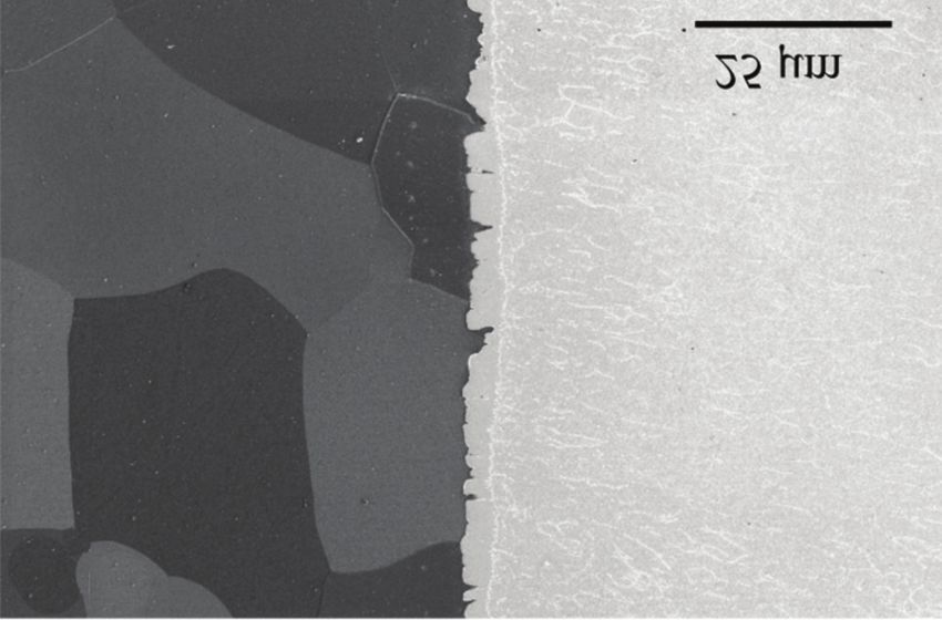
Kang Supplement March 2020.qxp_Layout 1 2/7/20 2:15 PM Page 68
WELDING RESEARCH
A
Fig. 1 — Mini-shear test specimen design.
Sigler et al. combined the MRD electrode with a multiple so-
lidification welding schedule to successfully weld aluminum
alloys to steel materials with acceptable joint strength (Refs.
5, 6). This welding process does not require the use of
prewelding treatment of material surfaces or the use of cov-
er plates such as those used by Qiu et al. (Ref. 2), or interlay-
ers used by Ibrahim et al. (Ref. 8) during welding.
It is well recognized that although the formation of IMCs
cannot be completely eliminated during RSW of aluminum al-
loys to steels, it is possible to minimize the thickness of the in- B
termetallic layer at the interface and improve weld strengths
through optimization of the welding process conditions. Fig. 2 — Macrostructure and microhardness measurements
Zhang et al. developed an optimal electrode design to spot of AA6022-T4 to IF steel resistance spot welds: A — Sched-
weld AA6008-T66 aluminum alloy and H220YD galvanized ule 1 (MRD/ballnose) as welded; B — Schedule 2 (MRD/MRD)
high-strength steel that produced an approximately 4.0-m- as welded.
thick intermetallic layer (Ref. 9). However, the alumimum
sheets were ground and degreased in acetone prior to welding, figuration. In addition to optical and scanning electron mi-
which is impractical in a production setting. Ibrahim et al. in- croscopy, focused ion beam (FIB) and transmission electron
serted an 80-m Al-Mg film between the AA6061 aluminum microscopy (TEM) were used to reveal the structure of the in-
alloy and 304 steel to reduce the IMC layer thickness to ap- termetallic layer at the interface. A mini-shear test was devel-
proximately 2 m (Ref. 8). oped to directly measure the shear strength of the interface of
Other factors can significantly affect joint strength. Both these welds and establish a quantitative relationship between
solidification porosity, which is characterized by gas pores, the microstructure and mechanical property of the interface.
shrinkage voids, and microcracks, as well as remnants of the
tough, adherent oxide film that forms on aluminum alloys can Materials and Experimental Procedure
accumulate along the faying interface adjacent to the inter-
metallic layer. Sigler and Carlson suggested these defects can
have a much greater impact on joint strength than the inter- Materials
metallic layer (Ref. 1).
In the present study, symmetric and asymmetric electrode The materials used in the study included AA6022-T4
combinations incorporating MRD electrodes were used in wrought aluminum alloy sheet in a thickness of 1.2 mm and
combination with multiple solidification weld schedules to hot-dip galvanized, IF steel in a thickness of 2 mm. The
weld wrought aluminum alloy AA6022-T4 to hot-dip galva- nominal chemical compositions of the two materials are pre-
nized, interstitial free (IF) steel sheet in the tensile shear con- sented in Table 1.
Table 1 — Chemical Composition of AA6022-T4 and IF Steel
Mg Si Cu Fe Mn Ti Zn Cr C Al Ni Nb P
6022 0.50 0.64 0.21 0.19 0.12 0.043 0.018 0.016 — Balance — —- —
IF steel — 0.0028 0.011 Balance 0.13 0.032 — 0.021 0.026 0.033 0.017 0.0040 0.016
68-s WELDING JOURNAL / MARCH 2020, VOL. 99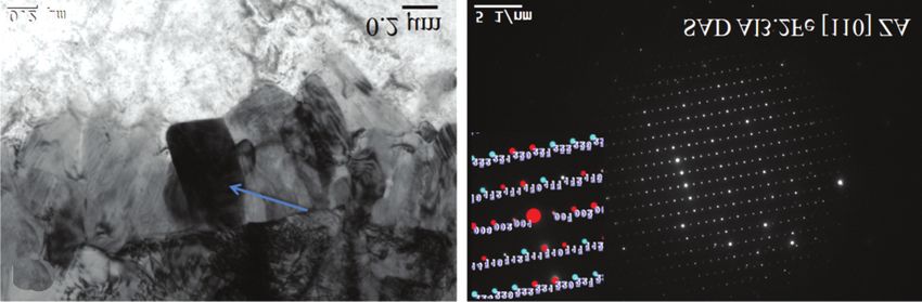
Kang Supplement March 2020.qxp_Layout 1 2/7/20 2:15 PM Page 69

                                                                                                              WELDING RESEARCH

         Fig. 3 — Macrostructure of AA6022-T4 to IF steel resistance
         spot welds from Schedule 1 (MRD/ballnose) after Stage 1 of
         the weld schedule. Arrows highlight porosity.

        Welding
                                                                                  A
            A medium-frequency direct current (MFDC) pedestal
        welding machine was used to prepare the spot weld speci-
        mens. Welding Technology Corp. (Farmington Hills, Mich.)
        inverter weld controls, along with RoMan Mfg. Inc. (Grand
        Rapids, Mich.) MFDC transformers, supplied current to the
        welding electrodes. Pneumatic actuators were used to apply
        weld force. Distilled water at ambient temperature was used
        to cool the welding electrodes at a flow rate of 1.5 to 2.0
        gal/min. All material stackups were welded with 19-mm-
        diameter CuZr C15000 copper alloy electrodes and with the
        aluminum sheet contacting the positive electrode.
            Two resistance welding schedules (Table 2) were used to
        weld aluminum-steel tensile shear specimens. It is noted that
        in Schedule 1 (MRD/ballnose), Sigler et al. (Refs. 10, 11) used           B
        an MRD electrode on the aluminum side only and a ballnose
        electrode on the steel side (asymmetric or hybrid electrodes),            Fig. 4 — AA6022 to IF steel resistance spot weld: A — Aver-
        while in Schedule 2, MRD electrodes were used on both the                 age maximum tensile loads; B — normalized tensile-shear
        aluminum and steel sides of the stackup (symmetric elec-                  strength by weld nugget area. Error bars represent one stan-
        trodes). The weld schedules were based on the multiple solidi-            dard deviation. The strength of tensile-shear samples pro-
        fication welding template developed by Sigler et al. (Refs. 7,            duced by resistance spot welding 1.2-mm AA6022-T4 to itself
        12). In Stage 1, a large weld nugget was created with consider-           is also shown for comparison.
        able penetration into the aluminum alloy sheet. The solidifi-
        cation of the weld nugget also solidified defects along the in-         ance spot weld. These weld schedule and electrode combina-
        termetallic layer that formed between the aluminum and                  tions were designed to create quality weld nuggets with a
        steel. These defects included gas porosity, shrinkage porosity,         thin intermetallic layer along the weld nugget periphery.
        and microcracking from remnants of oxide film incorporated                 As a comparison for tensile shear testing, the 1.2-mm
        into the weld nugget. After solidification, current flow was            AA6022-T4 sheet material was welded to itself using MRD
        restarted and a relatively thin layer of aluminum melted adja-          electrodes, and a weld schedule was developed specifically for
        cent to the intermetallic layer incorporating the defects previ-        spot welding aluminum (Ref. 13). This aluminum weld sched-
        ously described. Upon resolidification, porosity was consoli-           ule was designed to initially heat the workpieces to seat the
        dated close to the nugget center while the oxide film defects           electrodes (conditioning), form the aluminum weld nugget at
        were broken up and dispersed within the nugget.                         the faying interface (chaping), and grow the aluminum weld
            The two aluminum-steel welding schedules were de-                   nugget to the desired size (sizing). Weld size was targeted at
        signed to work in combination with the chosen electrodes.               5.5 to 6.0 mm, which would represent typical weld sizes in pro-
        Under load, stresses are highest at the notch root of a resist-         duction. After welding, half of the specimens were baked to

         Table 2 — Resistance Spot Welding Schedules of 1.2-mm-thick AA6022-T4 to 2.0-mm IF Steel Sheets

           Schedule          Electrodes       Weld Force      Preheat           Stage 1       Stage 1       Cool         Stage 2      Stage 2
                          Al/Steel or Al-Al      (N)                         (rms current)     (time)      (time)     (rms current)    (time)
            Al-Steel       MRD/Ballnose          3114      ~ 6 kA, 40 ms        12 kA        820 ms        100 ms        13.2 kA      745 ms
           Schedule 1
           Al-Steel          MRD/MRD             3781      ~ 6 kA, 40 ms        13 kA        250 ms        500 ms        13.4 kA      905 ms
          Schedule 2

             Al-Al           MRD/MRD             3114      ~ 8.1 kA, 30 ms       31 kA        22 ms         3 ms        28.8 kA       76 ms

                                                                                                        MARCH 2020 / WELDING JOURNAL 69-s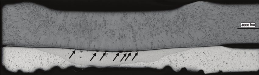
Kang Supplement March 2020.qxp_Layout 1 2/7/20 2:15 PM Page 70
WELDING RESEARCH
A B C
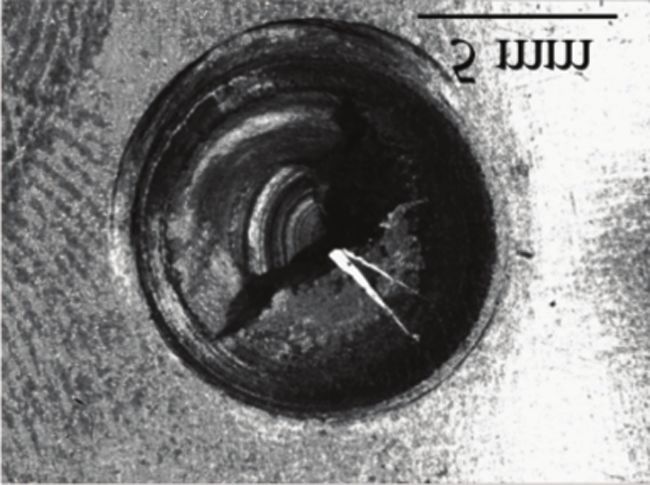
Fig. 5 — Fracture modes: A — AA6022-T4 to IF steel resistance spot welds made using Schedule 1 (MRD/ballnose) and exhibiting
partial fracture through the aluminum; B — AA6022-T4 to IF steel resistance spot welds made using Schedule 2 (MRD/MRD) and
exhibiting interfacial fracture; C — aluminum resistance spot weld showing button pullout.
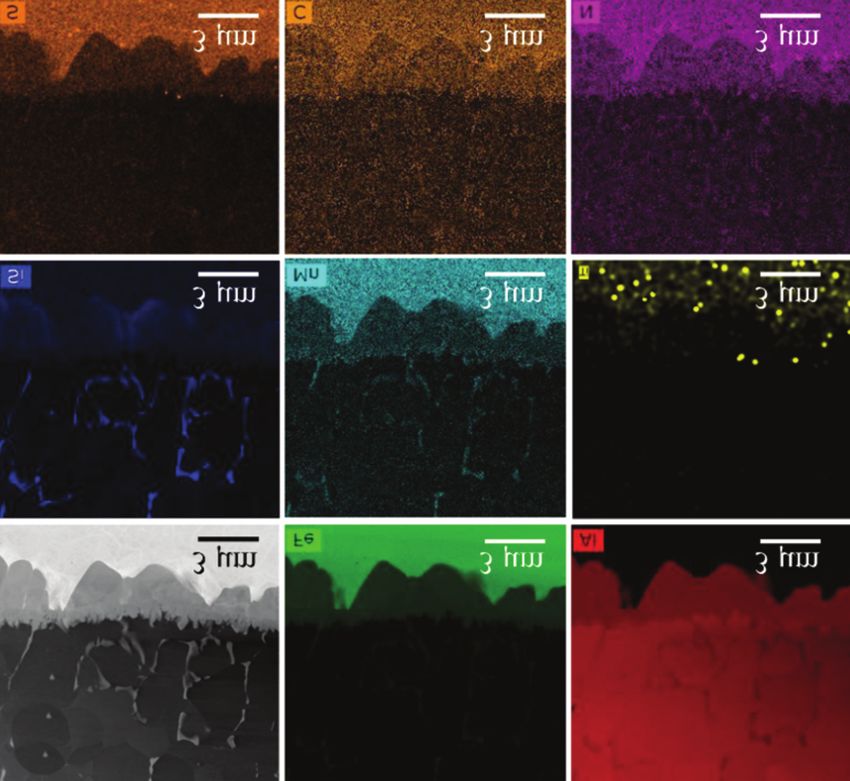
Fig. 6 — Measured shear strength of the intermetallic layers in Fig. 7 — EDS maps of Al and Fe of fractured surfaces of an
AA6022 to IF steel resistance spot welds. Error bars represent AA6022 to IF steel resistance spot weld produced using
one standard deviation. Schedule 2 (MRD/MRD).
simulate the ELPO bake process, which is 35 min holding time strength of the aluminum nugget, respectively.
at 175°C. Assuming isotropy and von Mises yield criterion for the
intermetallic layer and rearranging Equation 1 gives
Metallographic Analysis
Al nugget Al nugget
Metallography, optical, and scanning electron mi- L t Al nugget = 3 t Al nugget
croscopy, along with FIB and TEM, were used to reveal the IMC IMC
structure of the intermetallic layer at the interface. In addi- Al nugget
tion, microhardness measurements and quasistatic tensile = (1 ) 3t Al ( 1 ) 3t Al (2)
IMC
shear testing were performed. The details of these experi-
ments were described in previous studies by Kang et al. (Ref.
14) and Rao et al. (Ref. 15). where = 0.10 – 0.15 is the indentation ratio, i.e., the thick-
ness reduction in the aluminum side for the MRD electrode,
Mini-Shear Tests and Analysis IMC is the tensile strength of the intermetallic layer, and Al
nugget /IMC is usually greater than 1, i.e., the tensile strength
A novel mini-shear test specimen was designed and pre- of the aluminum weld nugget is greater than that of the in-
sented in Fig. 1. The test was developed to ensure that shear termetallic layer. The strength of the aluminum weld nugget
fracture occurred at the interface of the weld nugget with- is dependent, in part, on the thickness of the aluminum
out tensile fracture occurring in either the aluminum alloy nugget. During spot welding, the aluminum deforms and
weld nugget or the heat-affected zone (HAZ), which are the “indents” as heat is applied, reducing the aluminum thick-
weak locations, i.e., ness. This indentation was approximated as . Thus, the fi-
nal result in Equation 2, (1 – ) √3 tAl, gives a more conser-
L W IMC W t Al Al vative estimation of the shear zone length L.
nugget nugget (1)
Based on Equation 2, W = 2 mm and L = 1 mm were chosen
where L, W, tAl nugget, IMC, and Al nugget are the length and for the shear zone size of all the mini-shear test specimens
width of the shear zone, thickness of the aluminum weld used in the present study where tAl is 1.2 mm. The mini-shear
nugget, shear strength of the intermetallic layer, and tensile specimens were prepared using wire electrical discharge ma-
70-s WELDING JOURNAL / MARCH 2020, VOL. 99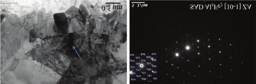
Kang Supplement March 2020.qxp_Layout 1 2/7/20 2:15 PM Page 71

                                                                                                            WELDING RESEARCH

         A                                                                     B

        Fig. 8 — Intermetallic profile as measured by light optical microscopy for the AA6022-T4 to IF steel resistance spot welds: A — Sched-
        ule 1 (MRD/ballnose); B — Schedule 2 (MRD/MRD). Filled symbols indicate no defects in the aluminum nugget near the intermetallic
        layer, and the open triangular symbol indicates ~ 100% of the aluminum interface near the intermetallic layer contained defects.

                                                                             the full, multistage weld schedule, Schedule 1 (MRD/ballnose),
                                                                             following Stage 1 and before Stage 2 of the weld schedule. The
                                                                             arrows highlight the interfacial porosity at the faying interface
                                                                             after Stage 1. This porosity is not evident in the macrostruc-
                                                                             ture presented in Fig. 2, which shows a weld structure after
                                                                             both Stage 1 and 2 of the weld schedule. This demonstrates
                                                                             the effectiveness of the complete two-stage multiple solidifica-
                                                                             tion weld schedule in consolidating and eliminating porosity
                                                                             near the faying interface. A thin, continuous layer of inter-
                                                                             metallic compounds formed at the faying interface between
                                                                             the aluminum and steel sheets. From Fig. 2, the average
                                                                             nugget diameter at the faying interface was measured to be
                                                                             8.6 and 8.3 mm for AA6022-T4 to IF steel resistance spot
                                                                             welds using Schedule 1 and 2, respectively.

        Fig. 9 — Measured intermetallic thickness in the center and at       Maximum Tensile Loads
        the periphery of the AA6022-T4 to IF steel resistance spot
        welds. Error bars represent one standard deviation.                      The average maximum tensile loads are directly compared
                                                                             to the nominal shear strength in Fig. 4. To calculate the nomi-
        chining. Since the high stress region is at the weld nugget pe-      nal shear strength, the average maximum tensile loads were
        riphery adjacent to the notch root, the shear zone (2 × 1 mm)        normalized by the weld nugget area using the weld nugget di-
        was entirely positioned at that location for all the resistance      ameter from tensile shear tests of the welded AA6022-T4 to IF
        spot welds tested.                                                   steel RSW stackups. The Al-steel resistance spot welds exhibit-
            The mini-shear test specimens were loaded in tension using       ed greater average maximum tensile loads than the analogous
        a standard MTS LandMark® 370 load frame with a 5-kN load             Al resistance spot welds. This is due, in part, to the larger alu-
        cell at a rate of 0.3 mm/min until specimen fracture occurred.       minum nugget diameters (8–9 mm) that develop in Al-steel
        After mini-shear testing, specimens were collected for fractog-      welds as compared to the standard, smaller Al RSW nugget di-
        raphy and energy dispersive spectroscopy (EDS) mapping               ameters (5–6 mm). It is difficult to grow Al resistance spot
        completed on both the aluminum and steel sides using a field         welds to the larger nugget diameters due to aluminum’s in-
        emission scanning electron microscope (FESEM).                       creased electrical and thermal conductivities, which leads to an
                                                                             increased propensity for internal expulsion with increasing
                                                                             current and weld time. Furthermore, to meet requirements for
        Experimental Results                                                 fatigue and other configurations of static mechanical tests, i.e.,
                                                                             coach peel and cross tension, Al-steel resistance spot welds re-
        Macrostructure and Microhardness                                     quire larger nugget diameters than Al resistance spot welds or
                                                                             even those outlined for steel resistance spot welds (d = 4√t) in
            Figure 2A, B are macrostructure images and the associated        Ref. 16. This is due to the fact that, in Al-steel resistance spot
        microhardness measurements of AA6022-T4 to IF steel resist-          welds, the weld nugget is contained only within the aluminum
        ance spot welds using two different multiple solidification          sheet and is separated from the steel sheet by a layer of inter-
        welding schedules. The welds in this study exhibited struc-          metallics; there is no mixing of metal between the aluminum
        tures that are typical for aluminum-steel (Al-steel) resistance      and steel sheets. Thus, it is necessary to have a greater load
        spot welds as described by Sigler and Carlson (Ref. 1). Al-steel     bearing area in Al-steel resistance spot welds to achieve accept-
        resistance spotwelds exhibited a planar interface with a large       able strengths. Growing large aluminum nuggets in Al-steel re-
        aluminum weld nugget that wets the steel surface, which is           sistance spot welds is relatively easy due to the resistive heat
        consistent with the results shown in Sigler and Carlson (Ref.        that is developed within the steel sheet. Once normalized for
        1). Defects such as gas porosity, shrinkage porosity, or cracking    weld diameter, the Al-steel and Al resistance spot welds exhib-
        were not observed within the aluminum weld nugget. Figure 3          ited approximately equivalent nominal shear strengths. The
        is a macrostructure image of a joint produced by interrupting        baked Al-steel resistance spot welds from Schedule 1

                                                                                                     MARCH 2020 / WELDING JOURNAL 71-s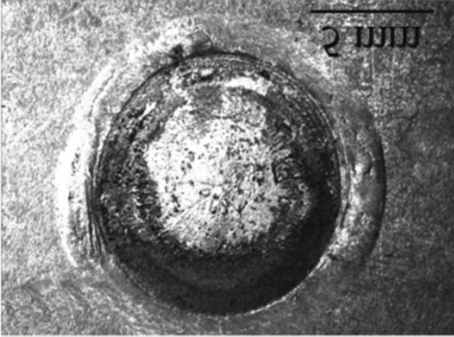
Kang Supplement March 2020.qxp_Layout 1 2/7/20 2:15 PM Page 72

    WELDING RESEARCH

         A                                                                    B

        Fig. 10 — AA6022 to IF steel interface at the periphery of the
        weld nugget produced using Schedule 1: A — FIB image; B —
        EDS maps in TEM.

        (MRD/ballnose) exhibited slightly higher nominal shear
        strength (81 MPa) than the Schedule 2 welds (70 MPa). This
        was attributed to partial fracture occurring through the alu-        Chen et al. used a specially designed shear jig to test interfacial
        minum for Schedule 1 welds, whereas interfacial fracture oc-         strength (Ref. 17). Significant difficulties were encountered
        curred for Schedule 2 welds — Fig. 5. Similar spot welds pro-        trying to align the test jig and the interface, leading to fracture
        duced in the 1.2-mm-AA6022-T4 sheet showed a nominal                 often occurring somewhere other than at the interface, partic-
        shear strength of ~ 86 MPa unbaked and 73 MPa baked. This            ularly for specimens with a thin intermetallic layer. The mini-
        difference is also primarily due to the different fracture modes.    shear test method proposed in the present study overcame
                                                                             these disadvantages and directly measured the shear strength
        Shear Strength of Intermetallic Layer                                of the intermetallic layer with good repeatability.

           Figure 6 compares the measured shear strength of the in-          Effects of Electrodes on the Intermetallic
        termetallic layer formed at the interface of the Al-steel welds      Thickness
        under the two different welding conditions. These results were
        taken from the perimeter of the weld nugget (refer to Fig. 1).
                                                                                Schedule 1 welds (MRD/ballnose) exhibited a greater de-
        The results show the intermetallic layer had an average shear
                                                                             gree of scatter in the measured intermetallic shear strengths
        strength of 64 MPa irrespective of welding condition. The re-
                                                                             than Schedule 2 welds (MRD/MRD) (refer to Fig. 6), although
        sults of EDS maps of fracture surfaces of the tested mini-shear
                                                                             similar average shear strengths were obtained for both sched-
        specimens (Fig. 7) confirmed that fracture occurred within the
                                                                             ules. The similarity in average shear strengths with the differ-
        intermetallic layer; thus, the measured strength was indeed
                                                                             ent degree of scatter are attributed to the morphology and
        the strength of the intermetallic layers.
                                                                             thickness distribution of the intermetallic layers. Figure 8
                                                                             shows the intermetallic profiles of the two welds as measured
        Discussion                                                           by light optical microscopy. Filled symbols indicate an inter-
                                                                             face area without any defects as previously described, while
        Advantages of Mini-Shear Specimens                                   the open triangular symbols indicate that ~ 100% of the inter-
                                                                             face was compromised by defects. These defects are not con-
            There is presently no standard procedure to directly meas-       tained within the intermetallic layer itself and instead are ob-
        ure the shear strength of aluminum to steel resistance spot          served in the aluminum nugget in the region near the inter-
        welds. The traditional method is to report the maximum load          metallic layer. The presence or absence of defects in the alu-
        capacity in tensile shear tests or nominal shear strength, i.e.,     minum near the intermetallic layer can influence the inter-
        the maximum load normalized by weld nugget area. However,            metallic thickness by acting as a diffusion barrier; thus, it is
        this method is only valid if an interfacial fracture occurs at the   important to characterize these defects. Both weld schedules
        interface without deformation of the weld nugget and the             produced quality, defect-free interfaces with thin intermetallic
        method is convoluted by the fact that the weld nugget diame-         layers along the nugget perimeter. Schedule 2 using the
        ter is unknown before testing. In scenarios where only partial       MRD/MRD electrode combination produced an overall much
        fracture occurs through the aluminum sheet, as shown in Fig.         thinner intermetallic layer than Schedule 1, which used the
        5, the measured nominal shear strength is invalid because the        MRD/ballnose electrode combination. The asymmetrical
        local stress status is not simple shear anymore. As seen in Fig.     MRD/ballnose electrodes modified the current density at the
        4, the nominal shear strength of the as-received specimen us-        faying interface between the aluminum and steel sheets. The
        ing Schedule 1 (MRD/ballnose) (80 MPa) appears to be higher          increased current density created more localized heat, which
        than that measured using mini-shear specimens (64 MPa).              encouraged the growth of the intermetallic layer.

        72-s WELDING JOURNAL / MARCH 2020, VOL. 99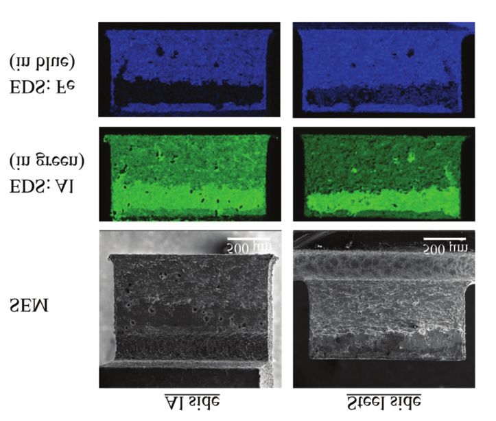
Kang Supplement March 2020.qxp_Layout 1 2/7/20 2:15 PM Page 73

                                                                                                                WELDING RESEARCH

         A

         B

        Fig. 11 — TEM results of specimen from Fig. 10 showing a crystallographic structure of: A — The smaller, needle-like intermetallic
        layer, FeAl3; B — the larger, tongue-like intermetallic layer, Fe2Al5. The blue arrows point to evidence of strain (discolorations) within
        the intermetallic layer.

            The thickness of the intermetallic layers as measured by            layer, a needle-like FeAl3 (Fig. 11A), and a larger tongue-like
        FESEM analysis of the resistance spot welds is plotted in Fig.          intermetallic layer, Fe2Al5 (Fig. 11B), at the interface of
        9, and agrees well with the data from light optical microscopy          AA6022 to IF steel resistance spot weld from Fig. 10.
        presented in Fig. 8. From both Figs. 8 and 9, the effect of lower
        heat and increased lateral solidification at the edges of the           Effect of Intermetallic Thickness on Shear
        weld produced thinner intermetallic layers in this region. By           Strength Response
        contrast, the intermetallic was thicker in the center of the weld
        where solidification occurs last; Chen et al. and Qiu et al. con-           A 2-μm-thick intermetallic layer at the weld nugget periph-
        cluded there was sufficient heat and time for diffusion to grow         ery was produced using either of the two weld schedule and
        the intermetallic layer (Refs. 2, 18). This effect was more pro-        electrode combinations. Furthermore, the symmetrical elec-
        nounced for specimens produced using Schedule 1 (MRD/ball-              trode combination of Schedule 2 (MRD/MRD) produced a
        nose) as this electrode combination concentrates more heat in           much more uniform intermetallic layer shear-strength re-
        the center of the weld.                                                 sponse compared to the asymmetrical electrode combination
                                                                                of Schedule 1 (MRD/ballnose), indicating that Schedule 2
        Intermetallic Characterization                                          (MRD/MRD) produced a more consistent quality joint. The in-
                                                                                creased scatter observed for Schedule 1 (MRD/ballnose) may
            As is typical of Al-steel spot welds, an intermetallic bilay-       be due to the resulting intermetallic profile (see Fig. 8). The
        er formed that included FeAl3 adjacent to the aluminum and              mini-shear test specimen configuration shown in Fig. 1 was
        Fe2Al5 adjacent to the steel, which is in agreement with the            designed to sample the intermetallic layer near the nugget pe-
        results obtained by Wan et al. (Ref. 19) — Fig. 10A. Silicon            riphery. Since the Schedule 1 (MRD/ballnose) electrode combi-
        enrichment was also observed in the aluminum weld nugget                nation produced a steeper gradient of intermetallic thickness
        near the intermetallic layer (refer to Fig. 10B), which may             near the nugget periphery than the more uniform intermetal-
        have acted to limit diffusion and growth of the intermetallic           lic layer produced by Schedule 2 (MRD/MRD), the shear test
        layer. Transmission electron microscopy results confirmed               may have sampled areas containing a thicker intermetallic lay-
        the crystallographic structure of the smaller intermetallic             er and produced greater spread in the strength data.

                                                                                                         MARCH 2020 / WELDING JOURNAL 73-s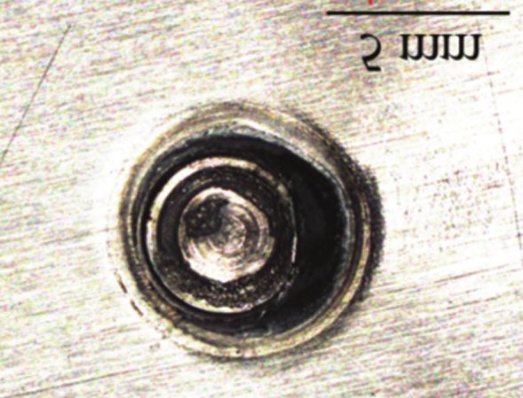
Kang Supplement March 2020.qxp_Layout 1 2/7/20 2:15 PM Page 74

    WELDING RESEARCH

        Conclusions                                                             M. J. 2018. Multi-Step Direct Welding of an Aluminum-Based
                                                                                Workpiece to a Steel Workpiece, U.S. Patent 9,999,938.
                                                                                    6. Sigler, D. R., Carlson, B. E., and Karagoulis, M. J. 2017. Multi-
            Resistance spot welds were produced between dissimilar              Stage Resistance Spot Welding Method for Workpiece Stack-up
        1.2-mm-thick wrought aluminum alloy AA6022-T4 and 2.0-                  Having Adjacent Steel and Aluminum Workpieces, U.S. Patent Ap-
        mm-thick hot-dip galvanized, IF steel using a MRD electrode             plication 20170106466.
        and multiple solidification weld schedules. In tensile-shear                7. Sigler, D. R., Carlson, B. E., Myasnikova, Y., and Karagoulis,
        configurations, the joints produced acceptable joint strength           M. J. 2015. Multi-Step Direct Welding of an Aluminum-Based
        compared to AA6022-T4 welded to itself. The following con-              Workpiece to a Steel Workpiece, U.S. Patent Application
        clusions can be drawn:                                                  20150053655.
            1) Asymmetric and symmetric electrode combinations re-                  8. Ibrahim, I., Ito, R., Kakiuchi, T., Uematsu, Y., Yun, K., and
        sulted in distinctively different intermetallic thickness pro-          Matsuda, C. 2016. Fatigue behaviour of Al/steel dissimilar resist-
                                                                                ance spot welds fabricated using Al–Mg interlayer. Science and
        files. The thinnest and most uniform profile was obtained
                                                                                Technology of Welding and Joining 21: 223–233. DOI: 10.1179/
        using the symmetric MRD electrode on both the aluminum                  1362171815Y.0000000086
        alloy and steel sheet; this led to improved joint quality and               9. Zhang, W., Sun, D., Han, L., and Li, Y. 2015.Optimised design
        much less scatter in shear-strength data distribution.                  of electrode morphology for novel dissimilar resistance spot weld-
            2) FIB and TEM results indicated the intermetallic layer            ing of aluminium alloy and galvanised high strength steel. Materi-
        consisted of two distinct layers, a needle-like FeAl3 adjacent          als and Design 85: 461–470. DOI: 10.1016/j.matdes.2015.07.02.
        to the AA6022-T4 sheet and a tongue-like Fe2Al5 adjacent to                 10. Sigler, D. R., Schroth, J. G., Carlson, B. E., Myasnikova, Y.,
        the IF steel sheet.                                                     and Yang, D. 2015. Aluminum Alloy to Steel Welding Process, U.S.
            3) A new mini-shear test was successfully developed to              Patent Application 20150096962
        directly measure the shear strength of the intermetallic lay-               11. Sigler, D. R., Carlson, B. E., and Karagoulis, M. J. 2017.
                                                                                Welding Electrode Cutting Tool and Method of Using the Same,
        er formed at the interface of these welds under different
                                                                                U.S. Patent Application 20170225262.
        welding conditions.                                                         12. Sigler, D. R., Carlson, B. E., and Karagoulis, M. J. 2017.
            4) The intermetallic layer exhibited an average shear               Multi-Stage Resistance Spot Welding Method for Workpiece Stack-
        strength of 64 MPa irrespective of welding conditions for in-           up Having Adjacent Steel and Aluminum Workpieces, U.S. Patent
        termetallic layers less than 2 μm thick at the weld periphery.          Application 20170206466.
                                                                                    13. Sigler, D. R., Carlson, B. E., and Karagoulis, M. J. 2018. Weld
                                                                                Schedule for Resistance Spot Welding of Aluminum Alloy Work-
         Acknowledgments                                                        pieces, U.S. Patent 9,969,026 B2.
                                                                                    14. Kang, J., Rao, H. M., Sigler, D. R., and Carlson, B. E. 2017.
           The authors gratefully acknowledge the financial support             Tensile and fatigue behaviour of AA6022-T4 to IF steel resistance
                                                                                spot welds. Procedia Structural Integrity 5: 1425–1432. DOI:
        from the Canadian Federal Government Energy Innovation
                                                                                10.1016/j.prostr.2017.07.207
        Program, General Motors Canada, and CanmetMATERIALS,                        15. Rao, H. M., Kang, J., Shi, L., Sigler, D. R., Carlson, B. E.
        Natural Resources Canada. The authors are grateful for help             2018. Effect of specimen configuration on fatigue properties of
        from Jean Paul Talon, Jie Liang, Harish Rao, Pei Liu, Jian Li,          dissimilar aluminum to steel resistance spot welds. International
        and Ruby Zhang on various aspects of the experimental                   Journal of Fatigue 116: 13–21. DOI: 10.1016/j.ijfatigue.
        work. Liting Shi thanks the support of her supervisor in                2018.06.009
        China, Professor Xu Chen, and the financial support from                    16. AWS D8.1M:2013, Specification for Automotive Weld Quality-
        China Scholarship Council and CanmetMATERIALS for her                   Resistance Spot Welding of Steel. Miami, Fla.: American Welding
        stay at CanmetMATERIALS, Hamilton, Ontario, Canada.                     Society.
                                                                                    17. Chen, J., Li, J., Shalchi-Amirkhiz, B., Liang, J., and Zhang, R.
                                                                                2014. Formation of nanometer scale intermetallic phase at inter-
         References                                                             face of aluminum-to-steel spot joint by welding-brazing process.
                                                                                Materials Letters 137: 120–123. DOI: 10.1016/j.matlet.
                                                                                2014.08.102
            1. Sigler, D. R., and Carlson, B. E. 2018. Impediments to devel-        18. Chen, N., Wang, H. P., Carlson, B. E., Sigler, D. R., and Wang,
        oping resistance spot welding processes for joining aluminum to         M. 2018. Fracture mechanisms of Al/steel resistance spot welds in
        steel. Proceedings of AWS SMWC XVIII.                                   coach peel and cross tension testing. Journal of Materials Processing
            2. Qiu, R., Iwamoto, C., and Satonaka, S. 2009. Interfacial mi-     Technology 252: 348–361. DOI: 10.1016/j.jmatprotec.2017.09.035
        crostructure and strength of steel/aluminum alloy joints welded by          19. Wan, Z., Wang, H. P., Chen, N., Wang, M., and Carlson, B. E.
        resistance spot welding with cover plate. Journal of Materials Pro-     2017. Characterization of intermetallic compound at the interfaces
        cessing Technology 209: 4186–4193. DOI: 10.1016/j.jmatprotec.           of Al-steel resistance spot welds. Journal of Materials Processing
        2008.11.003                                                             Technology 242: 12–23. DOI: 10.1016/j.jmatprotec.2016.11.017
            3. Arghavani, M. R., Movahedi, M., and Kokabi, A. H. 2016.
        Role of zinc layer in resistance spot welding of aluminium to steel.
        Materials & Design 102: 106–114. DOI: 10.1016/j.matdes.
        2016.04.033
            4. Mortazavi, S. N., Marashi, P., Pouranvari, M., and Masoumi,        JIDONG KANG (jidong.kang@canada.ca), LITING SHI, and BABAK
        M. 2011. Investigation on joint strength of dissimilar resistance         SHALCHI-AMIRKHIZ are with CanmetMATERIALS, Hamilton, Ont.,
        spot welds of aluminum alloy and low carbon steel. Advanced               Canada. SHI is also with the School of Chemical Engineering
        Materials Research 264–265: 384–389. DOI: 10.4028/                        and Technology, Tianjin University, Tianjin, China. DAVID R.
        www.scientific.net/AMR.264-265.384                                        SIGLER, AMBERLEE S. HASELHUHN, and BLAIR E. CARLSON are
            5. Sigler, D. R., Carlson, B. E., Myasnikova, Y., and Karagoulis,     with General Motors Global R&D Center, Warren, Mich.

        74-s WELDING JOURNAL / MARCH 2020, VOL. 99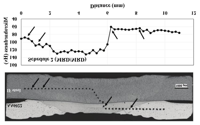
You can also read