Most Suitable Blade Inclination Angle for Multiphase Flow in Soybean Milk Machine
←
→
Page content transcription
If your browser does not render page correctly, please read the page content below

Journal of Applied Fluid Mechanics, Vol. 15, No. 2, pp. 349-361, 2022.
Available online at www.jafmonline.net, ISSN 1735-3572, EISSN 1735-3645.
https://doi.org/10.47176/jafm.15.02.32972
Most Suitable Blade Inclination Angle for Multiphase
Flow in Soybean Milk Machine
W. Xu1, L. Li1, H. Yin2 and H. S. Dou1†
1 Faculty of Mechanical Engineering and Automation, Zhejiang Sci-Tech University, Hangzhou, Zhejiang
310018, China
2 School of Mechanical and Electrical Engineering, Wenzhou University, Wenzhou, Zhejiang, 325035, China
†Corresponding Author Email: huashudou@yahoo.com
(Received May 06, 2021; accepted September 15, 2021)
ABSTRACT
The blade inclination angle of soybean milk machine is a key geometric parameter for efficient crushing. For
the purpose of obtaining optimal design, the gas-liquid two-phase flow field inside a soybean milk machine is
simulated. The gas holdup from simulation is in agreement with the experiment. The simulation result shows
that the lower blade A has a great influence on the internal flow field of soybean milk machine, while the
upper blade B has a small influence on the flow field. As the angle A increases, the peak value of radial
velocity decreases and moves to the interior of the cavity, so does the total pressure. When A changes from
-24° to -26°, the velocity vector at the bottom of the cavity changes from the connected state to the separated
state, and the pressure difference between the up and the bottom surface of blade A becomes large. When
A 24 , the flow field has the strongest turbulent kinetic energy and dissipation. When B 28 , the
pressure difference reaches the maximum. In summary, the best inclination angles are Aopt 24~ 26
and Bopt 28 , respectively.
Keywords: Soybean milk machine; Two-phase flow; Blade inclination angle; Numerical simulation.
1. INTRODUCTION soybean milk machine. It is found that when the
blade inclination angle is large and the angle
between guide ribs is acute, the crushing effect is
Soybean milk has been loved by people for its better.However, these studies were either
unique taste and rich nutrition. With the experimental studies or simulation studies of
improvement of living standards, people have single-phase media. There was no simulation study
higher and higher requirements on the taste and of two-phase media, and there were relatively few
nutritional content of soybean milk. Soybean milk studies on the influence of the blade angle on the
machine is a kind of small and fast equipment for internal flow field of the soybean milk
making soybean milk.The crushing effect of machine.Also as a rotary mixing machine, the
soybean milk machine can directly affect the taste principle of the agitator is similar to that of a
and nutritional content of soybean milk. Its various soybean milk machine, so the research on the
design parameters, including the shape of the cup, agitator can provide a certain reference for the
the blade installation height and the blade soybean milk machine.Some scholars (Jia et al.
inclination angle, have a certain impact on the 2020; Gradov et al. 2017; Zhang et al. 2018; Lane
soymilk crushing efficiency.How to improve the et al. 2002; Khopkar et al. 2005; Buffo et al. 2016;
design parameters of the soybean milk machine to Wang et al. 2012; Kerdouss et al. 2006) have done a
improve the crushing effect of the soybean milk lot of researches on the agitator. Through the
machine, thereby enhancing the taste and nutritional comparison of simulation results and experimental
content of the soybean milk, has become a hot topic results, they found that CFD (Computational Fluid
in the industry. Dynamics) can effectively predict the
Wang et al. (2011) and Song et al. (2017) have characteristics of the gas-liquid two-phase flow
carried out experimental or simulation research on field inside rotating machinery.The impeller is an
the influence of blade inclination angle and the important part of the agitator, its structure,
number ofguide ribs on the internal flow field of installation angle, etc. can directly affect the flow
field inside the agitator, and many scholars (Ren
W. Xu et al. / JAFM, Vol. 15, No. 2, pp. 349-361, 2022.
and Nan 2015; Wu et al. 2017; Shao et al. 2010;
Zhou et al. 2013) have studied it.The Euler-Euler
multiphase flow model has been used by many
scholars (Jia et al. 2020; Li et al. 2010; Wang et al.
2012; Zhang et al. 2010; Li et al. 2017) to predict
the two-phase flow field inside the agitator, and it is
found that the simulation results are in good
agreement with the experimental results.In the study
of gas-liquid two-phase flow, gas holdup is an (a) (b)
important research content. Previous scholars (Wu
et al. 2001; Tian et al. 2017; Li et al. 2017; Prakash
et al. 2019) studied a lot of content related to gas
holdup and gas-liquid two-phase distribution.
Through experiments and simulation comparisons,
it was proved that CFD can effectively predict the
gas-liquid two-phase distribution.Some of these
scholars (Wu et al. 2001; Tian et al. 2017) deduced
the relevant gas holdup rate equation by combining
experiments with theory.
By summarizing the previous researches, it is found
that it is meaningful to study the influence of the
blade inclinationangle on the two-phase flow field
inside the soybean milk machine.Considering the (c)
high rotation speed of the soybean milk machine
and the high turbulence intensity, in this study, the Fig. 1. Soybean milk machine model. (a) Cavity
Euler-Euler multiphase flow model and the RNG photo; (b) Cutter model;(c) Overall model.
(Re normalization group)k-ε turbulence model are
used to numerically simulate the two-phase flow
field inside the soybean milk machine.By analyzing
the variations of the flow field characteristics under Table 1 Geometric dimensions of the model
different blade inclination angles, the best blade Parameter Value
inclination angle combination is found. Model total height, h 142.67mm
Cup body height, h1 100mm
2. GEOMETRIC MODEL AND MESH The minimum radius of the cup 48.02mm
GENERATION body, r1
The maximum radius of the cup 53.25mm
2.1 Geometric model ofsoybean milk body, r2
machine Spoiler height, h2 75.27mm
Axis length, hs 16.3mm
The internal structure of the soybean milk maker is
shown in Fig. 1, which mainly includes a lid, a Length of blade A, l A 28mm
cavity and a cutter,and the cutter is composed of Length of blade B, lB 28mm
four blades. In this paper, the blade with the
downward inclination angle is defined as blade A, Inclination angle of blade A, A -
whichhas a negative inclination angle A ; the blade Inclination angle of blade B, B -
with the downward inclination angle is defined as the best inclination angle of the -
blade B, which has a positive inclination angle blade A, Aopt
B .The parameters of the model are shown in Table the best inclination angle of the -
1, andall the parameters are the real parameters blade B, Bopt
provided by Joyoung Company Limited, a famous
soybean milk machine company in China.The blade
angles of the original model are A 24 and The calculation region is divided into a rotating
B 24 . In this paper, the control variable is region and a stationary region. The rotating region
and the stationary region are connected by
adopted. First, the inclination angle of the B blade is interfaces, as shown in Fig.2 (a).Unstructured
kept unchanged, to study the influence of the meshes are used to generate global meshes.Since
inclination angle of blade A on the flow field, and the rotating region is an important part of the flow
obtain Aopt (the best inclination angle of the blade field and the accuracy of computation is important,
A).Then, keeping A unchanged, study the the grids inside the impeller and on the blade
surface are densified. Relatively speaking, the flow
influence of the inclination of blade B on the flow
field in static domain is the secondary part. In order
field, and obtain Bopt (the best blade B
to save computing resources, the grid of thatdoes
inclination angle). not need to be densified. Since the thickness of the
350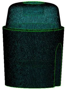
W. Xu et al. / JAFM, Vol. 15, No. 2, pp. 349-361, 2022.
front edge of blade is almost zero, the quality of the where, ρ is the fluid density; u, v, w are the velocity
grid near it is poor, the minimum aspect ratio of the vectors in the x, y, and z directions respectively; P
grid element is set to 0.3, which can ensure the is the pressure; μ is the dynamic viscosity
computational convergence. coefficient; f=ρg is the external force per unit
volume of the fluid.
2.2 Mesh generation
The Euler-Euler multiphase flow equation is:
q qq
q qVqq
t
(4)
qq pq m pq p mqpq S q
n
p 1
where, q represents the density of the q phase; q
represents the volume fraction of the q phase; q
represents the dependent variable of the multiphase
system; Vq represents the q phase velocity; S q
(a) represents the original term;n represents the number
of phases; m pq represents the mass transfer from the
q phase to the p phase; and pq is the direct
exchange of transported quantities (including
momentum, energy and components).
3.2 Boundary conditions
Considering the high speed and strong turbulence
intensity of soybean milk machine, the RNG k-ε
turbulence model and Euler-Euler multiphase flow
model were used to calculate the internal flow field
of soybean milk machine by CFD-CFX commercial
(b) (c) software.The rotating speed of the blade is 2000
Fig. 2. Domain division and mesh generation. (a) rpm and the rotating direction is counterclockwise
Domain division; (b) Stationary domain grid;(c) from the top view. The rotating domain and the
Rotating domain grid. stationary domain are connected by interfaces.The
frozen rotor model in multiple moving reference
frames (MRF) is adopted (Thakur and Wright 2003;
3. GOVERNING EQUATIONS AND Sanaie-Moghadam et al. 2015; Guini, 2014).The
NUMERICAL SIMULATION main phase is water, and the gas phase is 25℃air;
and the surface tension coefficient of gas-liquid is
set to 0.073N/m.According to the highest and
3.1 Governing equations lowest water level of this type of soymilk machine,
taking the middle value as the initial condition, the
The three-dimensional N-S equations and initial volume fraction of water and air is obtained
Euler-Euler multiphase flow control equation are as 0.435 and 0.565, respectively. The wall surface
used to numerically do the simulation. The N-S chooses a non-slip wall surface, without considering
equationsare: the influence of heat transfer and temperature,
considering gravity and buoyancy.
u u u u
u v w
t x y z 3.3 Grid independence verification
(1)
p 2 u 2u 2u Four sets of grids are used to verify the grid
fx 2 2 2
x x y z independence. The total pressure and static pressure
with coordinates of (30,30,30) are extracted and
v v v v plotted. The results are shown in Fig. 3.It can be
u v w seen that when the number of grids is greater than
t x y z
(2) or equal to 4.95 million, the total pressure and static
p 2v 2v 2v pressure have little error.In addition, Fig. 4 shows
fy 2 2 2
y x y z the two-phase fluids distribution for the four sets of
grids. Due to the instability of the gas-liquid
w w w w two-phase flow, even under the same number of
u v w grids, the gas-liquid two-phase distribution cannot
t x y z
(3) be completely consistent at different times.
p 2w 2w 2w However, when the number of grids reaches 4.95
fz 2 2 2
z x y z million, the bubble distribution above and below the
351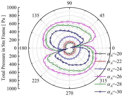
W. Xu et al. / JAFM, Vol. 15, No. 2, pp. 349-361, 2022.
blade is almost the same. In order to save calculation method used in this paper can
computing resources, the set of 4.95 million grids is effectively predict the two-phase flow field inside
selected as the calculation grid in this paper. the soybean milk machine.
Fig. 3. Grid independence verification.
Fig. 5. Comparison of gas holdup between
simulation and experiment (Song et al. 2007).
4 RESULTS AND DISCUSSIONS
4.1 Influence of different A on the flow
field
4.1.1 Two-phase fluids distribution of flow
field
(a) (b) Figure 6 shows the local gas-liquid two-phase fluids
distribution contour on the X-Y plane under
different A at B 24 . It can be clearly found that
A has a great impact on the gas-liquid two-phase
fluids distribution. With the increase of A , the
sizes of bubbles at the bottom of the blade and
above the tip of blade A first increase and then
decrease. The angle A 24~ 26 is a critical
state. When A is less than 24°, there are a lot of
(c) (d)
Fig. 4. Two-phase fluids distribution at the local bubbles at the bottom of the blade, and the bubbles
X-Y plane at different sets of grids.(a) 4 million; above the tip gradually become large. When A
(b) 4.95 million; (c) 6 million; (d) 7.1 million. is greater than 24°, the bubblesof the bottom of
blade disappear, and the bubbles near the tip rise
and become small.Thismay be related to the
The simulation results of this calculation method distance from the bottom to the blade A. When
have been verified in previous studies, and it is A is small, the distance from the bottom tothe
found that the velocity of the experimental results blade A is relatively greater and closer to the upper
and the one of simulation results are in good gas phase of thecavity. With the high-speed rotation
agreement (Li et al. 2020). In this paper, the of the blade, the air in the upper part of the cavity is
simulation effect of the calculation method on gas
carried into the lower liquid phase; when A is
holdup is verified.The turbulence model, two-phase
flow model and boundary conditions used in this larger, the blade A is far from the gas phase, so it is
paper are used to carry out numerical calculation for not easy to carry the air in the upper part of the
the agitator model in reference (Song et al. 2007). cavity into the liquid phase Figure 7 is an analysis
The comparison between the simulation results of about gas holdup β in the flow field. Figure 7(a)
gas content and the experimental results of that is shows the variation process of blade surface gas
shown in Fig.5. Due to the instability of gas-liquid content with A . It can be found that with the
two-phase flow and various errors of experiment increase of A , the gas content on the blade
and simulation, the values of experiment and
simulation are not completely consistent, but the surface first increases, and then a sudden change
development trend is the same. It is proved that the occurs at A 24~ 26 , from the maximum to
352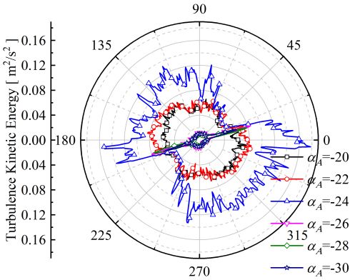
W. Xu et al. / JAFM, Vol. 15, No. 2, pp. 349-361, 2022.
(a) A 20 (b) A 22 c) A 24
(d) A 26 (e) A 28 (f) A 30
Fig. 6. Two-phase fluids distribution at the local X-Y plane at different A .
(a) (b)
Fig. 7. Variation trend of gas content at different A .(a) Variation of blade surface gas content; (b)
Variation of the average gas content on different height planes.
the minimum, and then continues to increase. 4.1.2Velocity vector distribution of the flow
Figure 7(b) shows the variation process of the
average gas content on different height planes under field
different A . y/h represents the ratio of the height of
Figure 8 shows the local velocity vector distribution
the plane to the total height of the model. on the X-Y plane under different A and
On the whole, β gradually becomes larger as the B 24 .It can be found that when A is small,
height increases. But between y/h =0.035~0.175, at
the flow field between the bottom of the blade and
A 24 ,β will increase first and then decrease, the corner of the cavity can connected, forming a
and the larger A , the larger β; when A 26 , β counterclockwise rotating vortex. It can ensure that
does not vary much. This is also consistent with the the fluid at the corners of cavity and the bottom of
two-phase distribution contour given earlier. blade circulates to the blades, and the bean dregs
will not remain in the corner of the cavity, thereby
improving the crushing efficiency. With the increase
353
W. Xu et al. / JAFM, Vol. 15, No. 2, pp. 349-361, 2022.
(a) A 20 (b) A 22 (c) A 24
(d) A 26 (e) A 28 (f) A 30
Fig. 8. Local velocity vector on X-Y plane at different A .
of A , the flow field of the bottom of cavity small, the flow field circulation at the corner of the
cavity and the bottom of the blade is good. With
gradually separates. The critical angle is
A 24~ 26 . After that, the corners of cavity A increasing, due to the Coanda effect, a row of
will form two self-circulating regions, forming a very small vortices will appear near the bottom wall
vortex rotating clockwise and counterclockwise of the cavity. This causes the bean dregs to form a
from bottom to top. This will cause the bean dregs self-circulation area at this position, which reduces
to self-circulate in the bottom corners, reducing the the probability of contact between the bean dregs
crushing efficiency. and the blade. The critical value of the angle is
A 24~ 26 .
Figure 9 shows the local velocity vector distribution
on the Y-Z plane. It can be seen that when A is A sampling line parallel to the X axis at the height
of y/h=0.14 on the X-Y plane is taken to analyze the
(a) A 20 (b) A 22 (c) A 24
(d) A 26 (e) A 28 (f) A 30
Fig. 9. Local velocity vector on Y-Z plane at different A .
354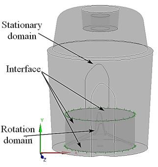
W. Xu et al. / JAFM, Vol. 15, No. 2, pp. 349-361, 2022.
radial distribution of the flow field. Figure 10 and pressure surface of the blade. Taking Fig. 12(a)
shows the variation of various flow field as an example, it can be found that the total
characteristics on the line, and x/r1 represents the pressure of the suction surface first decreases and
ratio of the coordinate in the X-axis direction on the then increases with A increasing, and reaches the
line to the minimum radius of the cavity r1. From
minimum value around A = 24 .The total
Fig. 10 (a) and (b),it can be found that the velocity
distribution has a strong symmetry, which is the pressure of the pressure surface first increases and
smallest at the center and wall of the cavity. From then decreases with A increasing, and reaches
the center to the wall of cavity, the velocity the maximum value around A = 26 .Therefore,
distribution first increases and then decreases. The
the maximum value of pressure difference should
peak velocity will move to the center of cavity with
be at A 24~ 26 .
A increasing and the peak velocity will gradually
decrease. The velocity of a mass point in the flow
field is affected by the velocity of the fluid near it
and the blade. As A increases, the height of A
blade decreases, so the peak velocity at the same
height will decrease and move to the center of
cavity. The variation of the total pressure is
basically the same as the velocity, but it should be
noted that, unlike the speed, the total pressure
maintains a minimum value at x / r1 0.1 near
the center of the cavity. With reference to Fig. 5, it
can be found that this may be owing to in this
region, the part at a height of y/h=0.14 is
completely in the gas phase; regardless of the
compressibility of the gas, the total pressure on the
same height plane of the gas phase remains
unchanged. (a)
4.1.3 Total pressure distribution across the blade
Due to symmetry, Fig. 11 only shows the local total
pressure contour near single blade. Column (a)
represents the contour of total pressure near blade A,
and column (b) represents the contour of total
pressure near blade B. It can be seen from column
(a) that with the increase of , the total pressure on
the pressure surface (upper surface) of the blade A
increases, while the one on the suction surface
(lower surface) decreases, and the low pressure
zone gradually moves from the tip of blade A to the
shaft of blade. On the contrary, with the increase of
A , it can be seen from column (b) that the total
pressure on the suction surface of the blade B
gradually increases, and the low pressure area
moves to the tip of the blade; the total pressure on (b)
the pressure surface does not change much. Total Fig. 10. Radial variation of velocity and total
pressure is related to velocity and static pressure, so
pressure at different A . (a) Radial variation of
this phenomenon will be analyzed in combination
with velocity in the following. velocity; (b) Radial variation of total pressure.
Because blade A is close to the bottom of the cavity, In Fig. 12(a) and (b), the total pressure of the
the pressure difference nearby that has a much suction surface has a small rebound with the
greater impact on the crushing effect than blade B, increase of height, especially in (b). In order to
and only the pressure difference across the blade A analyze this phenomenon, the static pressure and
is analyzed quantitatively in this study. Figure 12 velocity distributions on l2 are shown in Fig. 12 (c)
shows the quantitative analysis of the total pressure and (d), respectively. It can be seen that the static
change across the blade A on the X-Y plane. Figure pressure on the suction surface is the lowest, but the
12(a) and (b) represent the total pressure changes velocity close to the suction surface has a rebound.
on two sampling linesl1 and l2 parallel to Y-axis and This is because the velocity of a particle in the flow
d1and d2 away from Y-axis, respectively. The field is affected by the speed of the blade and the
interruption part is due to the flow field inside of particle near it. The closer to the blade, the more the
the blade can’t be collected, which is an objective velocity of flow field is affected by the blade speed.
fact. It can be found that the total pressure through The total pressure is composed of static pressure
the blade will vary abruptly, which is also due to and dynamic pressure, so the total pressure of the
sampling lines passing through the suction surface suction surface has a certain increase.
355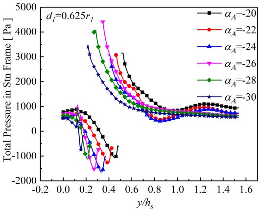
W. Xu et al. / JAFM, Vol. 15, No. 2, pp. 349-361, 2022.
A 20
A 22
A 24
A 26
A 28
A 30
(a) Blade A (b)Blade B
Fig. 11. Contour of total pressure distribution near blade at different A .
Figure 12(e) shows the variation of the maximum that the existence of guide ribs has a great influence
pressure difference ofl1 and l2 and its average value on the characteristics of the flow field. With the
with A .It can be clearly found that as A increase of A , the velocity increases gradually,
increases, the average pressure difference first but the amplitude is not very large. When the fluid
increases and then decreases. The angle particle flows by guide rib, the velocity will vary
A 24~ 26 is the critical angle range where from small to large and then to small. This is
the pressure difference varies suddenly. The greater because under the condition of constant flow rate,
the pressure difference, the greater the suction force due to the protrusion of the guide rib, the flow
of the blade on the particles at the bottom. channel becomes small, the flow velocity increases,
Therefore, considering only the pressure difference, and the velocity after flowing by the guide ribs
the inclination angle of the blade A should be taken decreases again. The total pressure first increases
A 24~ 26 , which can increase the contact and then decreases, and reaches the maximum
around A 26 .After the guide ribs, the total
probability of the soybean and blade, thereby
improving the crushing efficiency. pressure varies from large to small and then to large.
The trend of TKE(turbulent kinetic energy)variation
4.1.4 Variation of circumferential flow is similar to that of the total pressure, except that it
characteristics reaches the maximum around A 24 , and TKE
Take a circle with a radius of 37.5 mm on the height varies from the maximum to the minimum after
plane of the shaft as a sampling line to analyze the passing by the guide ribs. The distribution of TED
circumferential characteristics of the flow field. (turbulence eddy dissipation) is very chaotic, and it
Figure 13 shows the variation of various fluid reaches the maximum around A 24 in
characteristics at the sampling line. It can be found general.
356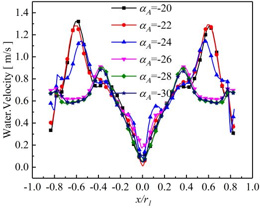
W. Xu et al. / JAFM, Vol. 15, No. 2, pp. 349-361, 2022.
(a) (b)
(c) (d)
(e)
Fig. 12. Quantitative analysis of total pressure near A blade at different A . (a) Total pressure
variation on l1; (b) Total pressure variation on l2; (c) Static pressure variation on l2; (d) Variation of
water velocity on l2; (e) Variation of the maximum pressure difference of l1 and l2 and its average value.
By analyzing the influence of A on the that in the model studied in this paper, the best A
characteristics of the gas-liquid two-phase flow should be Aopt = 24 ~ 26 .
inside the soybean milk machine, it can be found
357
W. Xu et al. / JAFM, Vol. 15, No. 2, pp. 349-361, 2022.
(a) (b)
(b) (d)
Fig. 13. Circumferential variation of various flow characteristics at different A .(a) Circumferential
variation of velocity; (b) Circumferential variation of velocity; (c) Circumferential variation of TKE; (d)
Circumferential variation of TED.
4.2 Influence of B on the flow field different B on the flow field.
4.2.1 Two-phase fluids distribution of flow Since the blade A is closer to the bottom of the
field cavity, the pressure difference nearby has a greater
Figure 14 shows the influence of different B on impact on the crushing effect of the soybean milk
machine, Fig. 16 shows a quantitative analysis of
the gas-liquid two-phasefluids distribution on the the total pressure across the blade A at different
X-Y plane at A 24 . It can be found that only B .It can be found that as B increases, the
the change of B does not have much effect on average pressure difference near blade A first
the gas-liquid two-phase distribution of the flow increases and then decreases, reaching the
field below the blade A, but it has a certain impact maximum near B 28 , which is most conducive
on the gas-liquid fluids distribution above the blade to crushing soybeans.
A.It can be seen that with the increase of B , the
gas holdup above the blade A has a certain increase. According to the aspects discussed above, the best
This is due to the increase of B , the blade B is angle of inclination of blade B should be around
closer to the gas phase, and it is easier to carry the Bopt 28 .
gas phase into the nearby liquid phase with the
rotation of the blade.
5 CONCLUSIONS
4.2.2 Velocity vector andtotal pressure
distribution near blade The gas-liquid two-phase flow field inside a
soybean milk machine is simulated. The results
It can be seen from Fig. 15 that only varying B show that the blade inclination angle of the soybean
has little effect on the velocity vector at the bottom milk machine has a great impact on its internal
of soybean milk machine.Therefore, the following two-phase flow field. The most suitable blade
is only a quantitative study of the influence of inclination angle formultiphase flow in the soybean
358W. Xu et al. / JAFM, Vol. 15, No. 2, pp. 349-361, 2022.
(a) B 20 (b) B 22 (c) B 24
(d) B 26 (e) B 28 (f) B 30
Fig. 14. Two-phase fluids distribution at the local X-Y plane at different B .
(a) B 20 (b) B 22 (c) B 24
(d) B 26 (e) B 28 (f) B 30
Fig. 15. Local velocity vector on X-Y plane at different B .
milk machine has been obtained. The main great influence on the velocity vector distribution of
conclusions can be drawn as follow. the flow field at the bottom of the cavity, while B
1. The inclination angle of the blade A, A , has a has almost no effect on that. As A increases, the
great influence on the gas-liquid fraction peak value of radial velocity decreases and moves
distribution, while the inclination angle of the blade to the interior of the cavity, so does the total
B, B , has a small influence on the two-phase pressure, which reduces the convective capacity of
fraction distribution. the bottom flow field. When A changes from -24°
to -26°, the velocity vector at the bottom of the
2. The inclination angle of the blade A, A , has a
359W. Xu et al. / JAFM, Vol. 15, No. 2, pp. 349-361, 2022.
(a) (b)
(c)
Fig. 16. Quantitative analysis of total pressure across A blade at different B . (a) Total pressure
variation on l1; (b) Total pressure variation on l2; (c) Variation of the maximum pressure difference of l1
and l2 and its average value.
cavity changes from the connected state to the In summary, the best inclination anglesare
separated state, this change of flow topology Aopt 24~ 26 ( Aopt 26 ) and Bopt 28 ,
weakens the ability of the particles crushing. Thus,
respectively.
the best inclination angle of the blade A, A ,should
be between -24° and -26°.
ACKNOWLEDGMENT
3. With the increase of A , the average pressure
difference between the up and the bottom surface of The authorswant to thank the help in the discussion
the blade A first increases and then decreases. At from H.Guo and H. Huang in Joyoung Group
A 24~ 26 , the pressure difference Company. This research is supported by the
increases sharply. The angle of blade B, B , has a research fund by Zhejiang Sc-Tech University
(21022094-Y).
certain effect on the pressure difference between the
up and the bottom surface of blade A. Generally, as
B increases, the pressure difference first REFERENCES
increases and then decreases. At B 28 , the
Buffo, M. M., L. J. Corrêa, M. N. Esperanca, A. J.
pressure difference across blade A is the largest,
G. Cruz, C. S. Farinas and A. C. Badino (2016).
which is the most suitable value for efficient
crushing. . Influence of dual-impeller type and
configuration on oxygen transfer, power
4. The inclination angle of the blade A, A , has a consumption, and shear rate in a stirred tank
great influence on the radial and circumferential bioreactor. Biochemical Engineering Journal
flow characteristics. Generally speaking, around 114, 130-139.
A 24 , the turbulent kinetic energy and eddy Gradov, D. V., A. Laari, I. Turunen and T. Koiranen
dissipation reach the maximum. (2017). Experimentally validated CFD model
360W. Xu et al. / JAFM, Vol. 15, No. 2, pp. 349-361, 2022.
for gas-liquid flow in a round-bottom stirred region boundary in multiple reference frames
tank equipped with Rushton turbine. method in a mixing system agitated by helical
International Journal of Chemical Reactor ribbon impeller using CFD. Journal of Heat
Engineering 15(2). and Mass Transfer Research 2(01), 31-37.
Guini, Y. (2014). Numerical simulation of Shao, X. M., X. L. Liu and Y. L. Li (2010).
multi-layer agitator blade in high temperature Experimental study of influence of the impeller
floating two-phase flow field. Biotechnology: spacing on flow behaviour of double-impeller
An Indian Journal 10(24):15984-15992. stirred tank. The Canadian Journal of
Chemical Engineering 81(6), 1239-1245.
Jia, H. L., F. Wang, J. X. Wu, X. Tan and M. Li
(2020). CFD research on the influence of 45° Song, Q., X. B. Ze and X. Han (2017). Study of the
disk turbine agitator blade diameter on the flow field in household soymilk maker in
solid-liquid mixing characteristics of the relation to spoiler ribs quantity and location.
cone-bottom stirred tank. Arabian Journal for International Conference on Mechanics and
Science and Engineering 45, 5741-5749. Mechatronics 5, 98-101.
Kerdouss, F., A. Bannari and P. Proulx (2006). CFD Thakur, S, and J. Wright (2003) CFD Predictions of
modeling of gas dispersion and bubble size in a Turbomachinery Flows Using Quasi-Steady
double turbine stirred tank. Chemical and Unsteady Models. Aiaa Fluid Dynamics
Engineering Science 61(10), 3313-3322. Conference & Exhibit.
Khopkar, A. R., A. R. Rammohan, V. V. Ranade and Tian, L., Y. Liu, J. J. Tang, G. Z. Lv and T. A.
M. P. Dudukovic (2005). Gas-liquid flow Zhang (2017). Variation law of gas holdup in
generated by a Rushton turbine in stirred vessel: an autoclave during the pressure leaching
CARPT/CT measurements and CFD process by using a mixed-flow agitator.
simulations. Chemical Engineering Science International Journal of Minerals Metallurgy
60(8-9), 2215-2229. and Materials 24(8), 876-883.
Lane, G. L., M. P. Schwarz and G. M. Evans (2002). Wang, G., L .J. Zhou, S. B. Xiong, Q. R. Li, M. C.
Predicting gas-liquid flow in a mechanically Wu and S. M. Zhao (2011). Effects of blender
stirred tank. Applied Mathematical Modelling structure and its force of soybean milk machine
26(2), 223-235. on soybean milk quality. Food Science 32(7),
162-167.
Li, L., H. S. Dou, Y. Du, H. W. Guo and H. Huang
(2020). Study on critical speed of vortex Wang, J. J., L. C. Li, X. P. Gu and L. F. Feng (2012).
rupture and gas-liquid two-phase flow in Progress on CFD simulation of gas-liquid
rotating soybean milk machine. International two-phase flow in stirred tank reactor. Process
Journal of Food Engineering 17(2), 97-110. Equipment & Piping 49 (001), 1-4.
Li, L.C., J. J. Wang, X. P. Gu, L. F. Feng, and B. G. Wu, M. C., C. S. Wu, J. Y. Liang, Y. T. Lei and B.
Li (2010). Computational fluid dynamics Yang (2017). Study on shear properties of six
simulation of bubble size andlocal gas holdup kinds of conventional agitator. Chemical
in stirred vessel. Journal of Zhejiang University Engineering (China) 45(08), 68-73.
(Engineering Science) 044 (012), 2396-2400,
Wu, Y., B. C. Ong and M. H. Al-Dahhan (2001).
2415.
Predictions of radial gas holdup profiles in
Li, X. J., X. P. Guan, N. Yang and M. Y. Liu (2017). bubble column reactors. Chemical Engineering
Experimental study and CFD simulation of Science 56(3), 1207-1210.
gas-liquid flow in a stirred tank using the
Zhang, Y. Q., X. Pan, Y. H. Wang, P. C. Luo and H.
EMMS drag model. Chemical Industryand
Wu (2018). Numerical and experimental
Engineering Progress 36(11), 4000-4009.
investigation on surface air entrainment
Prakash, B., T. Bhatelia, D, Wadnerkar, M. T. Shah, mechanisms of a novel long-short blades
V. K. Pareek and R. P. Utikar (2019). Vortex agitator. AIChE Journal 64(1), 316-325.
shape and gas-liquid hydrodynamics in
Zhang, Y., Y. Yong, Z. S. Mao, C. Yang, H. Sun, H.
unbaffled stirred tank. The Canadian Journal of
Wang and C. Yang (2010). Numerical
Chemical Engineering 97(6), 1913-1920.
simulation of gas-liquid flow in a stirred tank
Ren, P. F. and J. Nan (2015). CFD and experimental with swirl modification. Chemical Engineering
studies on the impact of impeller type on flow & Technology 32(8), 1266-1273.
field and floc size evolution in a stirred tank.
Zhou, C., H. W. Zhao and J. K. Zheng (2013).
International Conference on Advances in
Impact of Blade Installing Angle on Open
Energy & Environmental Science 1473-1481.
Turbine Stirrer. Machine Building &
Sanaie-Moghadam, M., M. Jahangiri and F. Automation 41(1), 27-30.
Hormozi (2015). Determination of stationary
361You can also read