Neutral model-based interfacing of 3D design to support collaborative project management in the process plant industry
←
→
Page content transcription
If your browser does not render page correctly, please read the page content below
Journal of Computational Design and Engineering, 2021, 8(3), 824–835

                                                                     doi: 10.1093/jcde/qwab017
                                                                     Journal homepage: www.jcde.org

RESEARCH ARTICLE

Neutral model-based interfacing of 3D design to

                                                                                                                                                        Downloaded from https://academic.oup.com/jcde/article/8/3/824/6275210 by guest on 08 October 2021
support collaborative project management in the
process plant industry
Hyunoh Lee1 , Chiho Noh2 , Seyun Kim1 , Byung Chul Kim                                                            3
                                                                                                                      , Jinpyo Park4 ,
Duhwan Mun 1, * and Soonhung Han2
1
 School of Mechanical Engineering, Korea University, 145 Anam-ro, Seongbuk-gu, Seoul 02841, South Korea;
2
 Department of Mechanical Engineering, Korea Advanced Institute of Science and Technology, 291 Daehak-ro,
Yuseong-gu, Daejeon 34141, South Korea; 3 School of Mechanical Engineering, Korea University of Technology
and Education, 1600 Chungjeol-ro, Byeongcheon-myeon, Dongnam-gu, Cheonan-si, Chungcheongnam-do
31253, South Korea and 4 SOFTHILLS Co., Ltd, 208, 27, Seonsui-ro 7-gil, Seongdong-gu, Seoul 04780, South Korea
*Corresponding author. E-mail: dhmun@korea.ac.kr     http://orcid.org/0000-0002-5477-0671

Abstract
The three-dimensional (3D) design data employed in a process plant construction project are generated during both the
basic design and detailed design stages and are used for various purposes throughout the life cycle of the project. After the
design stage, 3D design data are converted to a lightweight 3D format and utilized to support procurement, construction,
and audit work in a collaborative project management system. However, significant time and cost are incurred when
separate interfaces to convert design data are developed for each plant 3D computer-aided design (CAD) system. As an
alternative, a method exists to integrate an interface using a neutral model. After translating the 3D input design data for
the plant 3D CAD system to a neutral format, this study proposes an interface for use in collaborative project management
by converting the data into a lightweight 3D model. In addition, detailed techniques for implementing the proposed
interface are described. To verify the validity of the proposed neutral model-based 3D design data interface, translation,
inspection, and lightweighting experiments are performed using 3D design data for a synthesized natural gas production
plant project.

Keywords: 3D design model; collaborative project management; data interface; lightweight visualization; neutral
model; process plant

1. Introduction                                                                tenance. Even in a process plant construction project, 3D de-
                                                                               sign data are used as the master data throughout the project
With recent advances in geometric modeling, computer graph-
                                                                               period. The 3D design data also constitute the primary informa-
ics, and computing power, the manufacturing industry is now
                                                                               tion that engineering, construction, and procurement compa-
utilizing a wide range of three-dimensional (3D) models in all
                                                                               nies must hand over to the operator to support operation and
engineering fields, including design, manufacturing, and main-
                                                                               maintenance after plant construction.

Received: 8 December 2020; Revised: 12 February 2021; Accepted: 4 March 2021
C The Author(s) 2021. Published by Oxford University Press on behalf of the Society for Computational Design and Engineering. This is an Open Access

article distributed under the terms of the Creative Commons Attribution-NonCommercial License (http://creativecommons.org/licenses/by-nc/4.0/),
which permits non-commercial re-use, distribution, and reproduction in any medium, provided the original work is properly cited. For commercial
re-use, please contact journals.permissions@oup.com

                                                                                                                                              824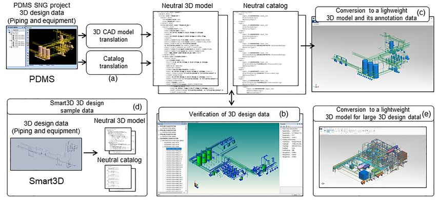
Journal of Computational Design and Engineering, 2021, 8(3), 824–835          825

     The 3D design data created in the basic design and detailed      ified by translating the test 3D design data, converting it into
design stages are stored in the native format of the plant 3D CAD     lightweight format data, and conducting collaborative work ex-
system. After the design stages, a collaborative project man-         periments.
agement system is utilized to support collaboration with ex-              This study provides three academic contributions compared
ternal organizations and manage internal business processes           to previous studies. First, a neutral 3D design model is proposed
during procurement, construction, and audits. The collaborative       to ensure the link between the 3D CAD model and catalog data
project management system provides various functions, includ-         that comprise plant 3D design data. Second, since large com-
ing project data integration, reviewing, and collaboration as well    plex facilities, including process plants, comprise an enormous
as engineering property checking, dimensional measurement,            number of parts, additional lightweighting techniques are ap-
interference, and collision checking, and 2D drawing generation.      plied as well as the conventional conversion to triangular mesh.
This collaboration function is implemented based on the 3D de-        Third, considering the proposed neutral 3D design model and
sign data of the corresponding plant.                                 additional lightweighting, this study proposes a method consist-
     The 3D design data used in the collaborative project man-        ing of two steps: translating plant 3D design data into neutral
agement system have a general-purpose lightweight 3D format,          model data and converting neutral model data to a lightweight
rather than the native format of the plant 3D CAD system. Large       3D model.

                                                                                                                                            Downloaded from https://academic.oup.com/jcde/article/8/3/824/6275210 by guest on 08 October 2021
complex facilities, such as process plants, generally consist of          The remainder of this paper is structured as follows. Sec-
millions or more parts. If a 3D CAD model that requires more          tion 2 reviews previous studies on lightweighting 3D CAD mod-
data than other shape representation methods is used, then            els and plant 3D design data exchange. Section 3 proposes a
more space is required to store the 3D design data, and data pro-     neutral model-based 3D design interface. Section 4 presents the
cessing consumes more computing power. Typically, a general-          translation of plant 3D design data into neutral model data.
purpose lightweight 3D model viewer incurs lower operating            The visualization-based verification of neutral 3D design data
costs than a 3D CAD system. Furthermore, if the 3D CAD model is       is presented in Section 5, and the conversion to a lightweight 3D
used in collaboration process, the company’s intellectual prop-       model is presented in Section 6. Section 7 discusses the results
erty, which is explicitly or implicitly included in the 3D CAD        of implementation and experiments. Conclusions and sugges-
model, could leak to external partners. Therefore, an interface       tions for future work are provided in Section 8.
that converts the 3D design data generated by the plant 3D CAD
system into a general-purpose lightweight 3D model is required
to support plant project collaboration management.
                                                                      2. Related Work
     Several types of systems are used for process plant 3D de-
sign. One method involves building an interface for each system       Methods to reduce the data size of 3D CAD models can be clas-
for direct conversion of the 3D design data into a lightweight        sified as model simplification (Kim & Mun, 2014a) or model
3D model. However, this requires significant time and cost dur-       lightweighting (Kwon & Mun, 2019). Model simplification re-
ing the development stage, which is disadvantageous in terms          duces the data size of the 3D CAD model using an evaluation
of maintenance. An alternative method is to extract the design        metric to calculate the importance of the various shape ele-
data required for collaborative work from the plant 3D CAD sys-       ments involved. Then, a simplification operation is applied to
tem in a neutral format and use these data for the collaborative      sequentially remove shape elements with low importance and
project management system. In this case, it is sufficient for the     to fill in any resulting voids until the required level of detail
collaborative project management system to provide an inter-          (LOD) is achieved (Kwon et al., 2015). LOD is a term commonly
face for the neutral model without considering the interface for      used in computer graphics and represents the degree of detail
all plant 3D CAD systems. Thus, this method is advantageous in        of the shape of a 3D model. The specific method used to sim-
terms of separating the plant 3D design and project collabora-        ply a 3D CAD model depends on the representation methods
tion stages, as well as for the development and maintenance of        of the model (Kwon et al., 2019). For example, 3D CAD models
the data conversion interface. Besides, external data interfaces      that take the B-rep form (Pratt et al., 2005) can be simplified by
of plant 3D CAD systems are boundary representations (B-rep)          analysing the composition pattern of the topological elements
or mesh formats. B-rep models have relatively large data size         constituting the model and then identifying and removing tar-
and thus are considered to be lightweight models. Mesh models         get elements to be simplified (e.g. faces; Koo & Lee, 2002; Kim
exported directly from a plant 3D CAD system also have large          et al., 2005; Sun et al., 2010) or by performing volume decompo-
data size if they do not go through additional lightweighting pro-    sition, creating a volume list, and then applying feature-based
cesses. Therefore, after plant 3D design data are translated into     simplification (Woo, 2009; Kim & Mun, 2014b, 2015).
neutral model data, additional lightweighting processes should            By contrast, model lightweighting reduces the data size of
be performed in 3D CAD models comprising the translated neu-          a 3D CAD model format, such as B-rep, by converting it to a
tral model data.                                                      3D lightweight model format, such as Jupiter tessellation (JT; JT
     This study proposes a method to extract the 3D CAD model         File Format, 2020), stereolithography (STL; STL file format, 2020),
(i.e. the 3D design data of the process plant, along with the         or wavefront object (OBJ; OBJ file format, 2020). Typically, the
equipment and material catalog) in a neutral format and con-          lightweight model represents the shape via a triangle mesh, and
vert it to a lightweight 3D model for use in project collaboration.   the size of the lightweight file depends on the triangle structure
For the translation of design data generated from the plant 3D        to be stored, the storage method (text or binary), and the com-
CAD system, a neutral model is defined by referring to the rel-       pression method. In addition to representing 3D shapes with tri-
evant industrial data standards. The consistency and accuracy         angles, the file size can be reduced by using a hybrid form of
between the 3D CAD model and the catalog constituting the 3D          constructive solid geometry primitives, e.g. the hybrid method
design data are further checked. The translated neutral 3D de-        proposed by Nguyen and Choi (2019). Eigner et al. proposed a
sign data are then converted into a lightweight 3D model and          method to increase the utilization of a lightweight model by
used in a collaborative project management system. Finally, a         combining a JT file and an extensible markup language (XML)
prototype system is developed, and the proposed method is ver-        file containing additional information (Eigner et al., 2010). More
826      Neutral model-based process plant 3D design interfaces

recently, Kwon and Mun proposed a method to reduce the size of         needs. Kim et al. also proposed a system architecture to generate,
a lightweight model by categorizing the types of parts that make       store, and manage the neutral catalog of components together
up the structures of ships and offshore plants, and then storing       with a capability to translate the neutral catalog into the native
the minimal triangle mesh for each part type without storing           format of a plant 3D CAD system (Kim et al., 2021).
unnecessary information (Kwon & Mun, 2020).                                Previous studies of plant 3D design data exchange generally
    Large complex facilities, including process plants, consist of     fall into two categories: the exchange of 3D CAD models (Li et al.,
many parts, which lead to the necessity of adopting additional         2011; Kim et al., 2017; Safdar et al., 2020) and the exchange of cat-
lightweighting techniques. First, when converting the 3D shape         alog data (Lee et al., 2012; Kim et al., 2020). To the best of knowl-
of a part having the B-rep format into a triangle mesh, if the         edge, no studies have investigated a method to translate plant
shape elements’ pattern is analysed and corresponds to a prim-         3D design data that ensures the link between the 3D CAD model
itive, it is converted and stored as a parameter value list rather     and catalog data that comprise plant 3D design data. This study
than a triangle mesh. In addition, the concept of a mesh block         proposes a method to translate both 3D CAD model data and
was introduced for swift rendering. Thus, by grouping the 3D           catalog data, ensuring the link between them. In addition, the
shapes of end nodes sharing the same visual properties and pro-        proposed method defines a neutral model used for this transla-
cessing them using a mesh block, the number of shape transmis-         tion.

                                                                                                                                               Downloaded from https://academic.oup.com/jcde/article/8/3/824/6275210 by guest on 08 October 2021
sions is significantly reduced. A lightweight model data struc-
ture was newly defined to cover new techniques applied in this
study.                                                                 3. Configuration of Neutral Model-Based
    The use of standards to manage facility asset information in          Interfacing of 3D Design to Project
the process plant industry has been investigated by Braaksma
                                                                          Management
et al. (2011). They reported that, in practice, information stan-
dards are applied only to a limited extent. The primary inter-         Detailed design in the plant 3D CAD system proceeds by search-
national standards used for the exchange of design informa-            ing the equipment and material catalog library, selecting the re-
tion in process plants include ISO 10303 (Owen, 1997), ISO 15926       quired plant items, and placing them in a 3D space for each in-
(Leal, 2005), and ISO 13584 (Cho et al., 2006). ISO 10303 deals with   dividual discipline, such as piping, equipment, structure, and
the exchange of product model data and provides an applica-            electricity, as well as heating, ventilation, and air condition-
tion protocol (AP) applicable to the process plant industry. ISO       ing (HVAC). The 3D CAD model contains information on the
15926 addresses the sharing and integration of process plant in-       assembly relationship, connection relationship, general proper-
formation, and ISO 13584 is relevant to the representation and         ties, and 3D arrangement (position and rotation) of equipment
exchange of parts library data. The published research on the ex-      and materials. Furthermore, the catalog used for modeling in
change of standard-based equipment specification information           this manner is stored and managed by the plant 3D CAD system
indicates that an equipment and material catalog system based          along with the resulting 3D CAD model in a separate database.
on ISO 15926 was established and used in ship and offshore plant       The catalog contains information on the 3D shape, specifica-
construction projects in the European Union (Irgens et al., 2004;      tions, and ports of the equipment and materials.
qHub, 2016). For example, Kim et al. implemented an ISO 15926-             As shown schematically in Fig. 1, considering the data items
based data storage prototype called a facade to store the equip-       managed by the plant 3D CAD system, a neutral model-based
ment and materials data of nuclear power plants and to pro-            3D design data interface is then defined to support the project
vide the data for related organizations (Kim et al., 2011). More       management of a process plant. The 3D design data interface
recently, Kwon et al. proposed a method to improve the sharing         consists of a 3D CAD model translation unit, a catalog transla-
environment of catalogs for equipment and materials by repre-          tion unit, a verification unit, and a conversion unit, i.e. conver-
senting specifications data using ISO 15926 (Kwon et al., 2016).       sion to lightweight 3D models. The 3D CAD model translation
In addition, Fiorentini et al. conducted a study to convert exist-     unit converts the model for each discipline created in the plant
ing engineering data of nuclear power plants to the ISO 15926          3D CAD system into a neutral format. The catalog translation
format (Fiorentini et al., 2013).                                      unit converts the equipment and material catalog into a neu-
    The ISO 15926 standard has also been used in studies on the        tral format, which is referenced in the plant 3D CAD system for
exchange of standards-based 3D CAD models and 2D drawings.             3D design. The neutral model representing the 3D design data
For example, Kim et al. proposed a method to exchange plant 3D         consists of two submodels representing a 3D CAD model and a
design models (Kim et al., 2017), while Li et al. referred to both     catalog based on the ISO 10303 and ISO 15926 standards. The
ISO 15926 and ISO 10303 AP 227 to develop a neutral model for          3D CAD model is defined by reference to the information re-
the exchange of 3D design models for ship outfitting between           sources provided by ISO 10303 AP 227, and the catalog model
the Tribon design and information system and the plant design          is defined by reference to the equipment and material specifica-
management system (PDMS; Li et al., 2011). Kim et al. proposed         tions in ISO 15926. The two submodels are primarily interlinked
a method for exchanging procedurally represented 2D drawing            via the catalog ID. The verification unit then checks the consis-
data using part 112 of the ISO 10303 standard (Kim et al., 2011).      tency and accuracy of the translated neutral 3D design data via
    With respect to the integration of standard-based process          integrated visualization. In terms of data consistency, this unit
plant life cycle information, Lee et al. applied the basic concepts    checks whether the catalog referenced by equipment and ma-
of ISO 15926 part 2 to propose a data model that supports the          terials constituting the 3D CAD model is provided in the cat-
effective operation and maintenance of large complex facilities        alog data. In terms of data accuracy, this unit checks whether
(Lee et al., 2012). More recently, Kim et al. proposed a data model    the information stored in the neutral 3D design data matches
based on ISO 15926 that can link the life cycle data of a pro-         the information generated by the plant 3D CAD system. Then,
cess plant including maintenance activities (Kim et al., 2020).        the conversion unit converts the neutral 3D design data into a
The data model proposed by Kim et al. provides information re-         lightweight 3D model. The neutral 3D CAD model is converted
sources that can link facility change history to design, manufac-      directly into a lightweight 3D model, while the neutral catalog is
turing, and installation information according to maintenance          converted into an annotation data format for use as an auxiliary
Journal of Computational Design and Engineering, 2021, 8(3), 824–835 827
Downloaded from https://academic.oup.com/jcde/article/8/3/824/6275210 by guest on 08 October 2021
Figure 1: Configuration of the neutral model-based 3D design interface.
support for the lightweight 3D model. As with the neutral 3D study deals exclusively with equipment and piping. Thus, the
design data, the lightweight 3D model and annotation data are Plant object is subdivided into a Piping System object and a Me-
primarily linked via the catalog ID. The converted lightweight 3D chanical System object (Fig. 2). The Piping System object stores
model is then used in the collaborative project management sys- the piping design results. Here, the Piping object refers to a set
tem for project data integration, project reviewing and collabo- of pipes that perform a specific function and represents the
ration, dimensional checking, interference checking, and cross- connection information between one Piping Segment and an-
section visualization. other via the Relation object. Each Piping Segment represents a
branch, where branches identify points at which a flow diverges
or changes. The hierarchical information of Piping Segment and
4. 3D Design Data Translation in a Neutral Piping Component is also represented via the Relation object.
Model The Piping Component object represents a plant item for fittings
As described above, a neutral 3D design data model was defined and has the component specification (CSPEC) property with re-
to translate the native 3D design data generated from the plant spect to catalog reference (CATREF) information. The Mechani-
3D CAD system into a neutral format. The neutral model of the cal System object is a collection of equipment that contains de-
3D design data consisted of a neutral 3D CAD model and a neu- sign information regarding individual equipment. The connec-
tral catalog model. Native 3D design data were translated into tion information between Equipment and Piping Component is
neutral 3D design data according to the method proposed in this also represented via the Relation object. In addition, Nozzle ob-
study. jects represent nozzles that connect equipment and piping. The
Different plant 3D CAD systems have different data struc- Nozzle object has a CATREF property with respect to CATREF in-
tures. Therefore, in this study, a neutral 3D CAD model and a formation.
neutral catalog model were defined by applying the concept of Objects under Plant have common Object Properties. The Ob-
reference data in ISO 15926 (Leal, 2005). The basic principle is ject Property contains object property information, i.e. Port, Id,
defining only classes, properties, and objects that are common Position, Spec, Insulation Spec, and Sat. Here, Port is a charac-
in the target domain in the explicit structure of the model and teristic of the Nozzle, Piping Segment, and Piping Component
representing detailed model information using separate refer- that indicates connection point information between pipes and
ence data. equipment or between individual pipes. The Id property repre-
For example, in the catalog model described in Section 4.2, sents unique identification information and is a characteristic
a class object is defined within the model. In addition, refer- of all objects (except Plant). The Position property indicates posi-
ence data for component and equipment classification, such tion information and is a characteristic of Equipment and Piping
as a valve, elbow, cap, and tee, are declared instances of class Component. The Spec property represents a set of catalog selec-
objects in auxiliary files. Accordingly, when translating catalog tion rules that satisfy given design requirements and is a charac-
data, data translation is performed using the mapping relation- teristic of Piping and Pining Segment. The Insulation Spec prop-
ship between the classification of components and equipment erty indicates information related to heat transfer (insulation)
of the commercial system and the classification of components treatment and is a characteristic of Nozzle. The Sat property is a
and equipment defined in the reference data. characteristic of Equipment and Piping Segment that represents
the address of the standard ACIS text (SAT) file in which the plant
3D shape information is stored.
4.1. 3D CAD model translation
As shown in Fig. 3, the native 3D CAD model is input to the
The neutral 3D CAD model is defined as shown in Fig. 2, where 3D CAD model translation module and translated to a neutral
the Plant object refers to the entire plant and a System is pro- 3D CAD model via (i) shape information extraction, (ii) schema
vided for each discipline. Among several possible systems, this mapping, and (iii) 3D CAD model data translation. Thus, the 3D828 Neutral model-based process plant 3D design interfaces
Downloaded from https://academic.oup.com/jcde/article/8/3/824/6275210 by guest on 08 October 2021
Figure 2: Data structure of neutral 3D CAD model.
Figure 3: Procedure to translate 3D CAD model data.
shape information in the native 3D CAD model is first extracted nent object, the mapping relationship varies depending on the
and stored as an SAT format file. Commonly used neutral 3D type of fitting; thus, a separate mapping file was defined manu-
CAD model formats include IGES, STEP, SAT, Parasolid-XT, JT, and ally and utilized in the mapping process. In the 3D CAD model
STL. Plant 3D CAD systems, e.g. AVEVA PDMS and HEXAGON data translation process, the native 3D CAD model data are pri-
Smart3D, support the SAT format. Thus, the SAT format was marily read, and their components are converted to those of the
adopted to store 3D shapes in the neutral model. As a result, neutral 3D CAD model using the mapping information stored in
the correspondence between the constituent objects of the 3D the mapping file. In the 3D CAD model, there are three mapping
CAD model of the plant 3D CAD system and the neutral 3D CAD files, i.e. the class file (stores classes comprising an assembly re-
model is defined via schema mapping. For the Piping Compo- lationship), the member file (stores components and equipmentJournal of Computational Design and Engineering, 2021, 8(3), 824–835 829
belonging to each class), and the attribute file (stores a list of at- For this verification, the neutral 3D design data are loaded
tributes for each member). The results are stored in the internal and then visualized in 3D. Consistency between the 3D CAD
data structure and are output as neutral 3D CAD model data in model and catalog is then further verified as follows. In the case
the XML format. of a piping design, the catalog ID stored in the CSPEC property
of the Piping Component object is extracted, and the presence
of a catalog item with the corresponding ID is checked for in
4.2. Catalog translation the neutral catalog. In addition, the equipment or material type
The neutral catalog model is defined as shown in Fig. 4. Here, properties recorded in the catalog are extracted to determine
the object Spec represents a set of catalog selection rules that whether they match the type of Piping Component object. For
satisfy the given design requirements, the Selection Filter Class equipment design, the catalog ID stored in the CATREF property
object defines a list of attributes required to select a catalog ac- of the equipment is extracted, and the presence of a catalog with
cording to the specifications (e.g. nominal diameter) and type the corresponding ID in the neutral catalog is checked. After ver-
of equipment and material (e.g. fitting, gasket, or bolt), and the ifying data consistency, data accuracy is verified by checking the
Selection Filter represents the selection rules for individual cat- following aspects: (i) whether the major information of the neu-
alogs according to the list of attributes. In addition, the Attribute tral 3D CAD model (e.g. assembly relationship, 3D shape, and
Downloaded from https://academic.oup.com/jcde/article/8/3/824/6275210 by guest on 08 October 2021
object represents the attributes of the Selection Filter Class ob- nonshape property) is displayed without issue; (ii) whether the
ject, and its values are represented as Attribute Value objects. displayed data exhibit discrepancies compared to the native 3D
The Class object represents types of equipment and materials, CAD; (iii) whether the major information in the neutral catalog
and the Property object represents the properties of a specific is displayed without issue; and (iv) whether the displayed data
equipment or material type, and its values are represented as exhibit discrepancies compared to the native catalog.
the Property Value object. The Catalog object stores property
values representing the functional and physical specifications
of specific equipment or material. The Catalog object stores the
property value of the corresponding class object in the Property 6. Conversion to Lightweight 3D Model with
Value object format. The types of equipment and materials rep- Annotations
resented by the catalog are identified depending on a Class ob-
ject. The Related Class relationship of the Class object and Child To convert the neutral 3D design data to a lightweight model,
Catalog relationship of the Catalog represent information about the data structure of the lightweight 3D model is defined as out-
the hole or nozzle in the equipment. In other words, the equip- lined in Fig. 7. This includes product manufacturing informa-
ment catalog and nozzle catalog are linked through the Child tion, structure, shape, material, and user-defined attributes. The
Catalog relation, and the Related Class relation represents the product structure contains information about the hierarchical
relationship between nozzle type and hole type. relationship between parts (equipment and materials) consti-
As shown in Fig. 5, the native catalog model is input to the tuting the product and is represented using the Assembly, Part,
Catalog translation module and translated into a neutral catalog and Instance objects. The Body object is connected to the Part
via schema mapping and catalog data translation. Here, schema object and contains detailed shape information for each part,
mapping defines the correspondence between Spec, Class, Se- including different phase information (i.e. Face, Loop, Edge, and
lection Filter, Property, Attribute, and Code for the catalog model Vertex). Here, the detailed shape is represented as a Mesh Block
of the plant 3D CAD system and the neutral catalog model. The object (i.e. a set of triangle sets) or a Triangle Set object in the
neutral catalog model is stored and used in an auxiliary file. In form of a triangle mesh. Note that a wireframe model has an
addition, the manually defined mapping relation is stored in a advantage over a mesh model in terms of data size; however,
separate mapping file and utilized in the translation process. using a wireframe model, it is difficult to satisfy all require-
In the catalog translation process, the neutral catalog model is ments of a collaborative project management system based on
loaded first, the components of the native catalog are converted a lightweight 3D model. For example, if a wireframe model is
to those of the neutral catalog using the mapping information used, there is a limit to implementing functions, e.g. construc-
stored in the mapping file, and the result is stored in the inter- tion quantity calculation and interference check. Thus, triangle
nal data structure. Finally, the result is output as neutral catalog meshes are primarily used. The geometries corresponding to the
data in the XML format. Face, Edge, and Vertex are represented by a nonuniform rational
B-spline (NURBS) Surface, NURBS Curve, and Point objects, re-
spectively.
5. Visualization-Based Verification of Data Each part corresponding to an end node in the product
structure includes 3D shape information, and the 3D shape
Consistency and Accuracy in Neutral Model
video must be transmitted to video memory during rendering.
The neutral 3D CAD model and neutral catalog are converted Large complex facilities, e.g. process plants, comprise millions of
independently from the plant 3D CAD system; thus, it is nec- parts; thus, it is difficult to ensure sufficient visualization perfor-
essary to verify the consistency between these two datasets. mance when rendering is performed while traversing the prod-
Thus, prior to the lightweighting process, the neutral 3D design uct structure. To solve this problem, the mesh block concept is
data are subjected to a visualization-based verification process, introduced to realize fast rendering. Thus, by grouping the 3D
where the data consistency and accuracy are evaluated by in- shapes of end nodes sharing the same visual properties and pro-
tegrated visualization of the translated neutral 3D design data cessing them using a mesh block, the number of shape transmis-
(Fig. 6). Specifically, the process determines whether the catalog sions is reduced significantly. Typically, visually distinguishable
information for each plant item constituting the neutral 3D CAD 3D CAD models are created by assigning one of 16 or 256 colors
model is provided from the neutral catalog. In addition, this pro- to each part; thus, even for an assembly containing thousands
cess verifies whether the 3D CAD model and catalog information of parts, using a mesh block enables suitable rendering via 16 or
are translated accurately. (at most) 256 shape transmissions.830 Neutral model-based process plant 3D design interfaces
Downloaded from https://academic.oup.com/jcde/article/8/3/824/6275210 by guest on 08 October 2021
Figure 4: Data structure of neutral catalog model.
Figure 5: Procedure to translate catalog data.
The lightweight 3D model is converted from a neutral 3D CAD ject that refers to this Part object can be used to create a product
model that is part of the neutral 3D design data. The product structure. Note that the Instance object only has location and
structure of a lightweight 3D model is then constructed from direction information; however, the 3D shape information is ob-
the assembly and connection relationships stored in the neu- tained by accessing the referenced Part object. In plant 3D CAD
tral 3D CAD model. After constructing the product structure, systems, a combination of primitives (e.g. cylinders and spheres)
the 3D shape of the part is transformed. In the neutral 3D CAD is often used to represent 3D shapes. Here, file size can be re-
model, the 3D shape is stored as a B-rep format SAT file. Dur- duced effectively by storing these primitives as a list of required
ing the conversion process, the neutral 3D CAD model is con- descriptive parameter values rather than storing them in a tri-
verted to a triangle mesh and stored in the Triangle Set object angle mesh. When converting the 3D shape of a part with the
of the lightweight 3D model. The general properties of the neu- B-rep format into a triangle mesh, if shape elements are ana-
tral 3D model are then converted to user-defined attributes of lyzed as corresponding to a primitive type, they are converted
the lightweight 3D model. Although neutral catalog data are not to a primitive rather than a triangle mesh, storing a parameter
converted separately, the catalog ID referenced by each part in value list of the primitive.
the Attribute object of the lightweight 3D model is stored to al-
low access of the lightweight 3D model to the neutral catalog.
In a plant 3D CAD system where modeling is performed us- 7. Implementation and Experiments
ing a catalog, individual parts, e.g. pipes, fittings, and structural
members, can occasionally have the same shape. In such cases, To verify the proposed neutral model-based 3D design data in-
after creating one Part object for the same part, the Instance ob- terface, a prototype system was developed according to theJournal of Computational Design and Engineering, 2021, 8(3), 824–835 831
Downloaded from https://academic.oup.com/jcde/article/8/3/824/6275210 by guest on 08 October 2021
Figure 6: Integrated visualization procedure for neutral 3D design data.
Figure 7: Data structure for lightweight 3D models.
above method. This prototype comprises four modules with the ACIS, and HOOPS3D libraries for conversion, processing, and vi-
implementation environments listed in Table 1. Here, the 3D sualization of the 3D shape files in the SAT format. In addition,
CAD model translation and catalog translation modules utilized the conversion unit to lightweight 3D models used InterOP to
the available programmable markup language (PML) to extract read the 3D shape files in the SAT format.
the unique 3D design data from the PDMS, and the neutral 3D Then, an experiment was performed in which the proto-
design data verification module used the commercial InterOP, type system was used to convert the 3D design data of the832 Neutral model-based process plant 3D design interfaces
Table 1: Implementation environments of modules comprising prototype system.
Units Modules Environments
3D CAD model translation unit 3D CAD model translation module - OS: MS Windows 10 pro 64 bit
- CPU: Intel Core i7 | RAM: 64.00 GB
- Language: C#
- Libraries: PML
Catalog translation unit Catalog translation module - OS: MS Windows 10 pro 64 bit
- CPU: Intel Core i7 | RAM: 64.00 GB
- Language: C#
- Libraries: PML
Verification unit of neutral model-based 3D design Neutral 3D design data verification - OS: MS Windows 10 pro 64 bit
module
- CPU: Intel Core i7 | RAM: 64.00 GB
- Language: C++
Downloaded from https://academic.oup.com/jcde/article/8/3/824/6275210 by guest on 08 October 2021
- Libraries: ACIS, InterOp, Hoops3D
Conversion unit to lightweight 3D models Lightweight 3D model conversion - OS: MS Windows 10 pro 64 bit
module
- CPU: Intel Core i7 | RAM: 64.00 GB
- Language: C++
- Libraries: InterOp
Figure 8: Experimental test data.
synthesized natural gas production plant modeled in the field to the 3D CAD model translation module and the catalog transla-
a lightweight 3D model, and the data were applied in the collabo- tion module, and these were then translated into neutral model
rative project management system. Here, the experimental data data. The translation proceeded according to the method de-
were the 3D design data of the Synthetic Natural Gas (SNG) plant scribed in Section 4, and the results are shown in Fig. 9a. This
completed in 2016 in Gwangyang, Jeollanam-do, South Korea. As neutral model translation method has an advantage; i.e. it can
shown in Fig. 8, the data used in this experiment were modeled be applied equally to the native 3D design data of other plant 3D
using the AVEVA PDMS, the piping 3D design data comprised CAD systems with different data structures. For example, the re-
5226 components, and the equipment 3D design data comprised sult of translating the 3D design sample provided by HEXAGON
616 pieces of equipment. Note that these data also included a Smart3D into neutral model data is shown in Fig. 9d.
catalog of 616 components and equipment. A visualization-based verification was performed on the 3D
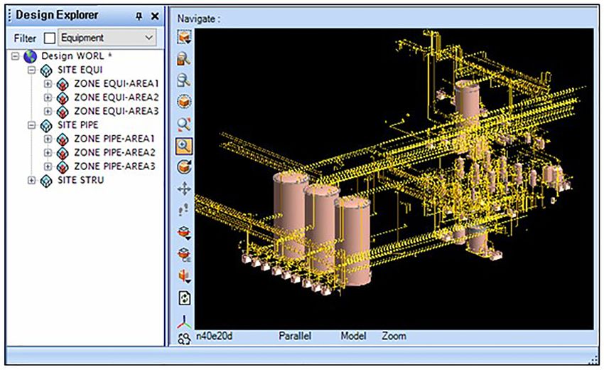
The process and results of converting the 3D design data into design data in the neutral format using the neutral 3D design
a lightweight 3D model are shown in Fig. 9. First, the native 3D data verification module (Fig. 9b). Here, the assembly relation-
CAD model and catalog were extracted from the PDMS using ship stored in the 3D CAD model is visualized in the tree viewJournal of Computational Design and Engineering, 2021, 8(3), 824–835 833
Downloaded from https://academic.oup.com/jcde/article/8/3/824/6275210 by guest on 08 October 2021
Figure 9: Neutral model-based interfacing of 3D design data to lightweight 3D model.
Table 2: Lightweight file sizes and conversion times for test cases.
PDMS SNG project Smart3D 3D design sample
Lightweight file format (neutral file: 481MB) (neutral file: 6.22MB)
This study File size 31.6 MB 1.89 MB
Conversion time 1 h 21 s 4 m 35 s
JT File size 122 MB 3.45 MB
Conversion time 52 min 24 s 3 min 29 s
window on the left-hand side of the module, the 3D shape of the shown in Fig. 9e. Here, the file size was reduced from 507 to 44.3
3D CAD model is visualized at the center, and the nonshape data MB for the sizable 3D design data. In addition, when the same
and catalog property information for the plant item selected by data were converted to the JT format, the file size was reduced
the user are visualized in the property window on the right-hand to 214 MB.
side of the module. These visualization-based verification ex- The completely converted lightweight 3D model was then
periments were used to determine whether all plant items nor- loaded from the collaborative project management system us-
mally referred to the catalog, and whether the information of ing the VIZZARD platform (SOFTHILLS) (SOFTHILLS VIZZARD,
the neutral 3D design data matched that of the native 3D design 2020) and checked for issues when performing the functions re-
data. quired for collaboration support (Fig. 10). Thus, the converted
As shown in Fig. 9c, the neutral 3D design data for which lightweight 3D model was applicable to project data integra-
visualization-based verification was completed were then con- tion, crosssection visualization, project reviewing, dimensional
verted to the lightweight 3D model for use in the collaborative checking, and interference checking without issue. Thus, by op-
project management system. As a result of lightweighting, the erating the collaborative project management system in web-
size of the entire model file for the PDMS SNG project was re- and mobile-based environments, 3D design data can be utilized
duced from 481 to 31.6 MB in conversion time of 1 h 21 s. When efficiently and effectively in part production, assembly, and in-
the same model file was lightened in the JT format, the file size stallation sites where the use of the plant 3D CAD system is dif-
was reduced to 122 MB, and the conversion time was 52 min 24 ficult.
s. In addition, a lightweighting experiment with the translated Since the collaborative project management system using a
neutral model data was performed on the Smart3D 3D sample, lightweight 3D model has small memory occupancy and data in-
as shown in Fig. 9d. As a result of lightweighting, the size of the teroperability through a neutral model, it can be used in virtual
entire model file for the Smart3D 3D sample was reduced from reality and augmented reality environments by mounting wear-
6.22 to 1.89 MB in conversion time of 4 min 35 s. When the same able devices on it in the smart manufacturing field (Han, 2020;
model file was lightened in the JT format, the file size was re- Rauch & Vickery, 2020). The data of the lightweight 3D model
duced to 3.45 MB, and the conversion time was 3 min and 29 s. used in the collaboration management system are small in size;
The results are summarized in Table 2. however, it is difficult to modify the model. Therefore, if a de-
To further verify the lightweighting capability, an experiment sign change occurs, the 3D design data must first be modified in
was performed on large 3D design data in PDMS RVM format, as the plant 3D CAD system, converted to a lightweight 3D model834 Neutral model-based process plant 3D design interfaces
Downloaded from https://academic.oup.com/jcde/article/8/3/824/6275210 by guest on 08 October 2021
Figure 10: Use of lightweight 3D model for project management support.
again according to the proposed method, and then uploaded in model must be extended to support other disciplines, including
the collaborative project management system. structural, electrical, and HVAC designs. Third, several mapping
files used to translate plant 3D design data into neutral model
data are currently being prepared manually. Thus, in future, it is
8. Conclusions necessary to develop a method to generate such mapping files
automatically or semiautomatically.
In this paper, a 3D design data interface has been proposed to
translate 3D design data created in a plant 3D CAD system ac-
cording to a neutral model defined in reference to relevant inter- Acknowledgments
national standards. In addition, after a lightweighting process, This research was supported by the Industrial Core Technology
the translated 3D design data can be used in a collaborative work Development Program (Project ID: 20000725&20009324), which
environment. The proposed interface primarily comprises a 3D was funded by the Ministry of Trade, Industry and Energy, Ko-
CAD model translation unit, a catalog translation unit, a 3D de- rea, and by the Basic Science Research Program (Project ID: NRF-
sign data verification unit based on a neutral model, and a con- 2019R1F1A1053542) of the National Research Foundation (NRF),
version to lightweight 3D models unit. The 3D CAD model trans- which was funded by the Ministry of Science and ICT (MSIT),
lation unit converts the 3D CAD model into a neutral format, and Korea.
the catalog translation unit converts the equipment and ma-
terial catalog into a neutral format. The 3D design data verifi-
cation unit checks the consistency and accuracy of the trans-
lated neutral 3D design data. Finally, the conversion unit con-
Conflict of interest statement
verts the inspected neutral 3D design data into a lightweight 3D None declared.
model.
A prototype system comprising four modules was imple-
mented to verify the proposed 3D design data interface. This
prototype was used to translate and reduce the data size of 3D References
design data of 5225 piping components and 616 equipment units Braaksma, A. J., Klingenberg, W. W., & van Exel, P. P. (2011). A
of a synthesized natural gas production plant using field data. review of the use of asset information standards for collab-
After converting the 3D design data to a lightweight 3D model, oration in the process industry. Computers in Industry, 62(3),
the lightweight 3D model was loaded and employed in a collab- 337–350.
orative project management system to confirm that there were Cho, J., Han, S., & Kim, H. (2006). Meta-ontology for automated
no issues relating to the use of the model in the system’s collab- information integration of parts libraries. Computer-Aided De-
oration functions. sign, 38(7), 713–725.
This study has three limitations to address. First, verifica- Eigner, M., Handschuh, S., & Gerhardt, F. (2010). Concept to en-
tion of the translated neutral 3D design data is performed vi- richen lightweight, neutral data formats with CAD-based
sually in many inspection items, including data values’ accu- feature technology. Computer-Aided Design and Applications,
racy, except for verifying whether required data fields are filled 7(1), 89–99.
and linking between 3D CAD model and catalog data is correct. Fiorentini, X., Paviot, T., Fortineau, V., Goblet, J. L., & Lamouri, S.
Therefore, follow-up studies on verification are required. Sec- (2013). Modeling nuclear power plants engineering data us-
ond, disciplines supported by neutral 3D design models are lim- ing ISO 15926. In Proceedings of 2013 International Conference
ited to piping and equipment designs, and the neutral 3D design on Industrial Engineering and Systems Management (IESM)(edsJournal of Computational Design and Engineering, 2021, 8(3), 824–835 835
D. Aboutajdine, A. Skalli, B. Benchekroun, & A. Artiba ) (pp. national Journal of Advanced Manufacturing Technology, 105(1–4),
901–906). IEEE. 1329–1342.
Han, S. (2020). A review of smart manufacturing reference mod- Kwon, S., Mun, D., Kim, B. C., Han, S., & Suh, H. W. (2019). B-
els based on the skeleton meta-model. Journal of Computa- rep model simplification using selective and iterative vol-
tional Design and Engineering, 7(3), 323–336. ume decomposition to obtain finer multi-resolution models.
Irgens, T. A., Hansen, T., & Haenisch, J. (2004). PLCS pilot for New Computer-Aided Design, 112, 23–34.
Norwegian frigates. In Proceedings of the 13th Product Data Tech- Kwon, K., & Mun, D. (2020). A method to minimize the data size
nology Europe Symposium. of a lightweight model for ship and offshore plant structure
JT File Format. Available online: https://en.wikipedia.org/wiki/JT using part characteristics. Journal of Marine Science and Engi-
(visualization format) (accessed on 1 August 2020). neering, 8(10), 763.
Kim, S., Lee, K., Hong, T., Kim, M., Jung, M., & Song, Y. (2005). Leal, D. (2005). ISO 15926 Life cycle data for process plant:
An integrated approach to realize multi-resolution of B-rep An overview. Oil & Gas Science and Technology, 60(4),
model. In Proceedings of the 2005 ACM Symposium on Solid and 629–637.
Physical Modeling. Lee, S., Han, S., & Mun, D. (2012). Integrated management of facil-
Kim, B. C., Teijgeler, H., Mun, D., & Han, S. (2011). Integration of ity, process, and output: data model perspective. Science China
Downloaded from https://academic.oup.com/jcde/article/8/3/824/6275210 by guest on 08 October 2021
distributed plant lifecycle data using ISO 15926 and Web ser- Information Sciences, 55(5), 994–1007.
vices. Annals of Nuclear Energy, 38(11), 2309–2318. Li, J., Kim, I., Lee, S., Han, S., Lee, C., Cheon, S., Lee, W., An, K., Cho,
Kim, B. C., Mun, D., Han, S., & Pratt, M. J. (2011). A method to ex- G., Hwang, J., & Mun, D. (2011). Sharing piping CAD models
change procedurally represented 2D CAD model data using of ocean plants based on international standards. Journal of
ISO 10303 STEP. Computer-Aided Design, 43(12), 1717–1728. Marine Science and Technology, 16(1), 76–83.
Kim, B. C., & Mun, D. (2014a). Feature-based simplification of Nguyen, C. H. P., & Choi, Y. (2019). Triangle mesh and boundary
boundary representation models using sequential iterative representation combined approach for 3D CAD lightweight
volume decomposition. Computers & Graphics, 38, 97–107. representation for collaborative product development. Jour-
Kim, B. C., & Mun, D. (2014b). Stepwise volume decomposition nal of Computing and Information Science in Engineering, 19(1),
for the modification of B-rep models. The International Journal 011009.
of Advanced Manufacturing Technology, 75(9–12), 1393–1403. OBJ file format, URL: https://en.wikipedia.org/wiki/Wavefront .
Kim, B. C., & Mun, D. (2015). Enhanced volume decomposi- obj file(accessed on 1 August 2020).
tion minimizing overlapping volumes for the recognition of Owen, J. (1997) STEP: An introduction. (2nd ed.). Information Ge-
design features. Journal of Mechanical Science and Technology, ometers.
29(12), 5289–5298. Pratt, M. J., Anderson, B. D., & Ranger, T. (2005). Towards the
Kim, B. C., Jeon, Y., Park, S., Teijgeler, H., Leal, D., & Mun, D. (2017). standardized exchange of parameterized feature-based CAD
Toward standardized exchange of plant 3D CAD models us- models. Computer-Aided Design, 37(12), 1251–1265.
ing ISO 15926. Computer-Aided Design, 83, 80–95. qHub, URL: https://epim.no/eq-hub/(accessed on 20 October
Kim, B. C., Kim, B., Park, S., Teijgeler, H., & Mun, D. (2020). ISO 2016).
15926–based integration of process plant life-cycle informa- Rauch, E., & Vickery, A. R. (2020). Systematic analysis of needs
tion including maintenance activity. Concurrent Engineering, and requirements for the design of smart manufacturing
28(1), 58–71. systems in SMEs. Journal of Computational Design and Engineer-
Kim, B. C., Lee, H., Mun, D., & Han, S. (2021). Lifecycle manage- ing, 7(2), 129–144.
ment of component catalogs based on a neutral model to Safdar, M., Jauhar, T. A., Kim, Y., Lee, H., Noh, C., Kim, H., Lee, I.,
support seamless integration with plant 3D design. Journal Kim, I., Kwon, S., & Han, S. (2020). Feature-based translation
of Computational Design and Engineering, 8(1), 409–427. of CAD models with macro-parametric approach: issues of
Koo, S., & Lee, K. (2002). Wrap-around operation to make multi- feature mapping, persistent naming, and constraint transla-
resolution model of part and assembly. Computers & Graphics, tion. Journal of Computational Design and Engineering, 7(5), 603–
26(5), 687–700. 614.
Kwon, S., Kim, B. C., Mun, D., & Han, S. (2015). Graph-based sim- SOFTHILLS VIZZARD, http://www.softhills.net/vizzard.ht
plification of feature-based three-dimensional computer- ml(accessed on 9 November 2020).
aided design models for preserving connectivity. Journal of STL file format, URL: https://en.wikipedia.org/wiki/STL (file for
Computing and Information Science in Engineering, 15(3), 031010. mat) (accessed on 1 August 2020).
Kwon, S., Kim, B. C., Hwang, H., Mun, D., & Han, S. (2016). En- Sun, R., Gao, S., & Zhao, W. (2010). An approach to B-rep model
hancement of equipment information sharing using three- simplification based on region suppression. Computers &
dimensional computer-aided design simplification and digi- Graphics, 34(5), 556–564.
tal catalog techniques in the plant industry. Concurrent Engi- Woo, Y. (2009). Automatic simplification of solid models
neering, 24(3), 275–289. for engineering analysis independent of modeling se-
Kwon, K., & Mun, D., (2019). Part recognition-based simplifica- quences. Journal of Mechanical Science and Technology, 23(7),
tion of triangle mesh models for ships and plants. The Inter- 1939–1948.You can also read