Novel Bloch wave excitation platform based on few layer photonic crystal deposited on D shaped optical fiber
←
→
Page content transcription
If your browser does not render page correctly, please read the page content below
www.nature.com/scientificreports
OPEN Novel Bloch wave excitation
platform based on few‑layer
photonic crystal deposited
on D‑shaped optical fiber
Esteban Gonzalez‑Valencia1,2*, Ignacio Del Villar3,4 & Pedro Torres1
With the goal of ultimate control over the light propagation, photonic crystals currently represent
the primary building blocks for novel nanophotonic devices. Bloch surface waves (BSWs) in periodic
dielectric multilayer structures with a surface defect is a well-known phenomenon, which implies
new opportunities for controlling the light propagation and has many applications in the physical and
biological science. However, most of the reported structures based on BSWs require depositing a large
number of alternating layers or exploiting a large refractive index (RI) contrast between the materials
constituting the multilayer structure, thereby increasing the complexity and costs of manufacturing.
The combination of fiber–optic-based platforms with nanotechnology is opening the opportunity for
the development of high-performance photonic devices that enhance the light-matter interaction
in a strong way compared to other optical platforms. Here, we report a BSW-supporting platform
that uses geometrically modified commercial optical fibers such as D-shaped optical fibers, where a
few-layer structure is deposited on its flat surface using metal oxides with a moderate difference in RI.
In this novel fiber optic platform, BSWs are excited through the evanescent field of the core-guided
fundamental mode, which indicates that the structure proposed here can be used as a sensing probe,
along with other intrinsic properties of fiber optic sensors, as lightness, multiplexing capacity and
easiness of integration in an optical network. As a demonstration, fiber optic BSW excitation is shown
to be suitable for measuring RI variations. The designed structure is easy to manufacture and could be
adapted to a wide range of applications in the fields of telecommunications, environment, health, and
material characterization.
Electromagnetic surface waves (ESWs) are widely studied due to their potential applications in photonic devices
and sensing applications in areas such as biology, chemistry, physics, among o thers1–3. The first ESWs to be
observed were the surface plasmon polaritons (SPPs), a type of resonance located at the interface between a
metal film and a dielectric medium represented by the collective motion of electrons4. SPPs are characterized
by their short propagation length, caused by the strong absorption of the metal layer4,5, which thus limits the
scalability of such structures. Therefore, there is a high interest in surface waves between two dielectric media,
since the ESWs can propagate at the interface with minimum losses4,6. Most of the proposed applications based
on ESW excitation exploit the Kretschmann configuration, which is illumination through a bulky prism, at an
angle greater than the critical angle of the multilayer. However, ESW excitation in optical fibers is considered as
a more compact, lightweight and robust alternative, with potential for remote and live monitoring applications1,
and for “lab-on-fiber” platforms that can be applied for communication and sensing p urposes7.
Some of the most relevant ESWs in dielectric interfaces are the Bloch surface waves (BSWs)8, which consists
of electromagnetic waves that propagate at the interface between two dielectric media, where at least one of them
is periodically non-homogeneous in the normal direction to the interface9. In the simplest case, the periodi-
cally non-homogeneous medium consists of a one-dimensional photonic crystal (1DPC)8,10. Its confinement is
due to total internal reflection from the side of the homogeneous dielectric and to the photonic bandgap in the
1
Escuela de Física, Universidad Nacional de Colombia - Sede Medellín, A.A. 3840 Medellín,
Colombia. 2Department of Electronic and Telecommunications Engineering, Instituto Tecnológico Metropolitano,
Medellín, Colombia. 3Institute of Smart Cities (ISC), Public University of Navarra, 31006 Pamplona,
Spain. 4Electrical and Electronic Engineering Department, Public University of Navarra, 31006 Pamplona,
Spain. *email: egonzalv@unal.edu.co
Scientific Reports | (2021) 11:11266 | https://doi.org/10.1038/s41598-021-90504-z 1
Vol.:(0123456789)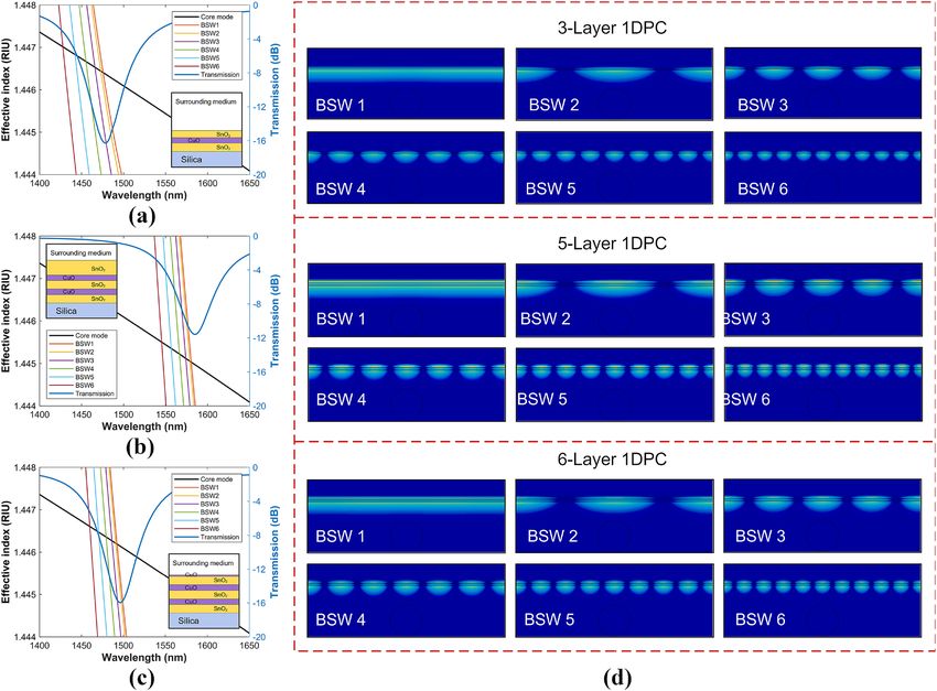
www.nature.com/scientificreports/
1 DPC11,12. Thus, the BSW dispersion relation is below the light line of the homogeneous dielectric, and within the
photonic bandgap13,14. Moreover, multilayers are wavelength scalable and may be designed to sustain TE- and/
or TM-polarized BSWs at a broad range of wavelengths from near UV to IR15.
As a BSW propagates along the surface, it couples light to the multilayer system16. Thus, the multilayer design
has been optimized for low losses by appropriately choosing the thicknesses and number of periods. Most devices
based on BSW excitation require a 1DPC with a large number of layers–higher than 1210,12,17–25. These configura-
tions have been used in 1DPCs consisting of bilayers of materials with refractive index (RI) differences as small as
0.2 refractive index units (RIU)12,17–19 up to moderate differences of 0.8 R IU10,20–25. However, there are reported
studies that show that it is possible to excite BSWs at the interface of 1DPCs with less than 10 layers5,26–31. A
common feature of these structures is the relatively large RI difference of the materials used in the 1DPC bilay-
ers, ranging from values greater than 0.8 R IU32,33 to 2 RIU and even h igher5,31. The resonant generation of BSWs
via prims or grating coupling is an active field of current research in applications such as s ensors13,21,31,34,35,
surface-enhanced Raman s pectroscopy36,37, fluorescence-based d etection29,38–40, enhanced nonlinear e ffects41,42,
and integrated optics18,20. However, very few investigations on the BSW excitation in optical fibers have been
published, and not all of them have experimental v erification19,23,30,32,43.
In this work, we report a BSW excitation platform that uses geometrically modified commercial optical fib-
ers such as D-shaped optical fibers, with a few-layer 1DPC deposited on its flat surface using metal oxides with
a moderate difference in RI. Indeed, it was recently demonstrated that D-shaped fibers can operate in reflective
configuration44, which indicates that the structure proposed here can be used as a probe that can be used as a
catheter, a nasogastric probe, or even for chemical mapping of surfaces. The combination of fiber–optic-based
platforms with the nanotechnologies is opening the opportunity for the development of high-performance pho-
tonic devices that enhance the light-matter interaction in a strong way compared to other optical platforms. In
this novel ESW excitation platform, BSWs are excited through the evanescent field of the core-guided fundamen-
tal mode. The 1DPC consist of alternating thin layers of tin oxide (SnO2) and copper oxide (CuO), which have the
real part of the RI higher than that of the pure silica, with which the commercial optical fibers are manufactured,
and the imaginary part low but not n egligible45. A high real part of the RI provides strong in-plane confinement of
the light and enables the development of compact and low loss integrated photonic devices. The nano-deposition
technique used for generating the 1DPC was DC sputtering and a theoretical analysis was made, which permit-
ted to analyze and validate the experimental results. Although most of the BSW excitation platforms require a
large number of layers or materials with a large difference in RI, we demonstrate that even a 3-layer stack on the
fiber-based excitation platform can sustain TE-polarized BSWs using a 1DPC consisting of materials that have
a moderate difference in RI. To the best of our knowledge, this constitutes the first experimental observation of
BSWs excitation in laterally polished commercial optical fibers. Moreover, the 1DPC is easy to fabricate and the
results are promising for the development of new types of all-fiber photonic devices and sensing applications.
Results and discussion
Design of the structure. The structure designed to experimentally verify the excitation of BSWs in optical
fiber consists of a commercially available single mode D-shaped fiber optic and a few-layer 1DPC coating the flat
surface of the fiber, as shown in the schematic of Fig. 1a. In this figure, the two insets zoom the central region,
where the multilayer deposited on the flat surface of the fiber can be identified. It is a structure that is easy to
implement, manipulate, and allows to reduce associated costs46. There are many studies on thin-film deposi-
tions on geometrically deformed fibers, where the core-guided evanescent field can be coupled to w aveguides47,
surface gratings48, metal films to excite SPPs46, and metal oxides to generate lossy-mode resonances49–52, among
others. The 1DPC consist of alternating thin layers of tin oxide (SnO2) and copper monoxide (CuO) that exhibit
a moderate RI contrast, close to 0.3 at the near infrared region (1.84 for SnO2 and 2.137 for CuO at 1550 nm),
and relatively low extinction coefficient values (0.01 for SnO2 and 0.02 for CuO, which were selected to match
the experimental results reported below).
Because the RI difference between the SnO2 and the CuO thin films is moderate, the thickness of the alter-
nating layers of the 1DPC are chosen to achieve optimum BSW excitation condition and low losses. To design
multilayers that match the conditions for BSW, the thicknesses of the high and low refractive index layers d are
calculated based on the forbidden transmission band at the desired resonance wavelength of a 1DPC band-
gap material11, d = /(4n) , where n is the refractive index within the high and low refractive index layers. For
example, using this expression for the wavelength = 1550 nm, it is found that the thicknesses of the SnO2 and
CuO are 212 nm and 182 nm, respectively. Since the resonance wavelengths of BSWs are determined by the
thicknesses of the multilayer, BSWs in the NIR region can be achieved by varying the layer thicknesses. In the
present work, the thicknesses of the SnO2 and CuO layers are 300 and 200 nm, respectively, which were chosen
so that the multilayer exhibits a photonic bandgap around the near infrared, which is the common range of
operating wavelengths in fiber-optic communication components (1150–1650 nm), and a TE-polarized BSW
can be excited. The properties of a BSW are more easily understood from the study of the dispersion diagram of
the semi-infinite multilayer. Figure 1b shows the dispersion band diagram of the proposed SnO2/CuO 1DPC for
TE polarization, in which the radiative zones (blue) and the non-radiative zones (white) are distinguished for
propagation within the multilayer stack. The figure also shows the light line (black) of the surrounding medium,
which was taken to be 1.33. The dispersion band diagram of the semi-infinite multilayer was calculated with the
transfer matrix method53. The β axis is the propagation constant of the incident light, which is parallel to the
surface of the multilayer structure, and the frequency axis corresponds to the wavelength range of interest. The
surface modes occur in the white area that correspond to the photonic bandgap of the dispersion band diagram.
This allows us to excite the BSW modes of the structure, whose propagation properties strongly depend on the
1DPC termination. In practice, however, we have to deal with a finite multilayer, such as the one depicted in
Scientific Reports | (2021) 11:11266 | https://doi.org/10.1038/s41598-021-90504-z 2
Vol:.(1234567890)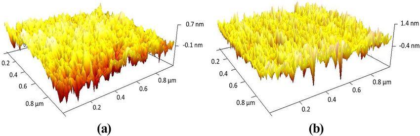
www.nature.com/scientificreports/
Figure 1. (a) Schematic of a single mode D-shaped fiber coated with a 6-layer 1DPC. The orange and
purple layers represent the SnO2 and CuO, respectively. (b) Band diagram of the SnO2/CuO 1DPC for the
TE polarization. The black line is for light in the surrounding medium (1.33), the red and green lines are the
calculated BSW modes at the 6-layer 1DPC with a termination layer of 24 nm and 140 nm, respectively. (c)(d)
(e) BSW electric-field intensity distributions at the 1DPC with termination layer of 24 nm [at 1270 nm (c), and
1500 nm (d)] and 140 nm [at 1270 nm (e)].
Fig. 1a. The strict sense of bandgaps with well-limited edges should be reconsidered since with so few periods
they are vaguely defined. Although it seems to be a problem with the position of some cases of surface waves
because they appear outside the ideal gaps, one can adhere to the criteria of the evanescent character of the
fields and the ability of these systems to guide energy along the surfaces54, which results in a loss of energy in
the transmitted light. Dispersion curves and electric field distributions for the fundamental BSW (BSW1) were
numerically calculated using the commercial software package FIMMWAVE (details on the parameters used
for the simulations are given in the “Materials and methods” section). For demonstration purposes, Fig. 1b
also shows the relation of the BSW1 dispersion curves in the photonic bandgap for different thicknesses of the
termination layer—the CuO layer adjacent to the surrounding medium—of the 6-layer 1DPC outlined in the
inset of Fig. 1a. It can be observed that the BSW1 mode dispersion curve with a 24 nm CuO termination layer
(red line) appears near the upper and lower edges of the bandgap, whereas the BSW1 dispersion curve with a
140 nm CuO termination layer (green line) lies near the lower edge of the bandgap. The electric-field intensity
profiles in Fig. 1c–e correspond, respectively, to the orange, yellow and green dots, on the dispersion curves of
the BSW1 modes in Fig. 1b. As expected, the field is highly enhanced at each surface of the multilayer and has
an exponentially decaying shape inside the crystal. Interestingly, the field distributions in Fig. 1c,d, to the best
of our knowledge, are the first evidence that in a finite periodic system of alternating dielectric layers bounded
asymmetrically by dielectric media, the surface modes of each boundary can interact and become coupled to
a variable degree depending on both the truncation of the outer layers as the total thickness of the 1DPC (see
supplementary material). It is worth noting that the excitation of coupled surface modes has been reported in
dielectric–metal–dielectric structures to excite long-range surface plasmon p olaritons55,56 and finite dielectric
54 57
1DPCs bounded by air and SiC gratings . For the surface modes that occur near the center of the bandgap
(red dot), the mode is more confined and the attenuation by the multilayer stack is stronger. For the modes close
to the edges (yellow dot), the evanescent field penetrates much further into the structure and the attenuation is
relatively weaker. Therefore, the fiber-based BSW platform can be designed based on the desired application.
Strong field enhancement is needed for sensing and nonlinear applications, while modes with longer propagation
length are required for integrated o ptics16.
Similar to the prism-based BSW excitation, the fiber-based BSW can be efficiently excited as long as the
effective index of the core-guided mode coincides with that of the B SW32. Besides sensitivity, one of the main
determining factors for the resonance performance is the absorption loss of the multilayer materials. Increasing
such losses yields considerably broadened resonance (see supplementary material). The number of layers in
Scientific Reports | (2021) 11:11266 | https://doi.org/10.1038/s41598-021-90504-z 3
Vol.:(0123456789)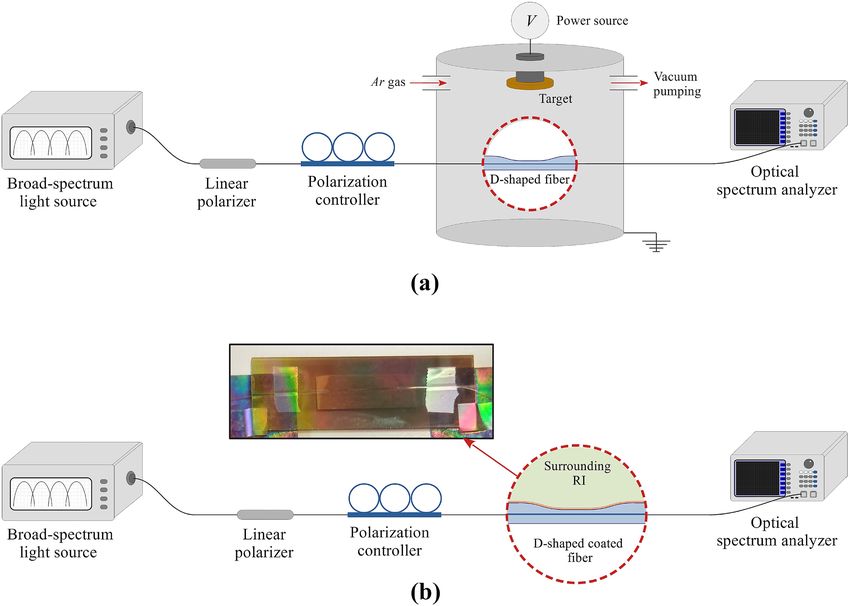
www.nature.com/scientificreports/
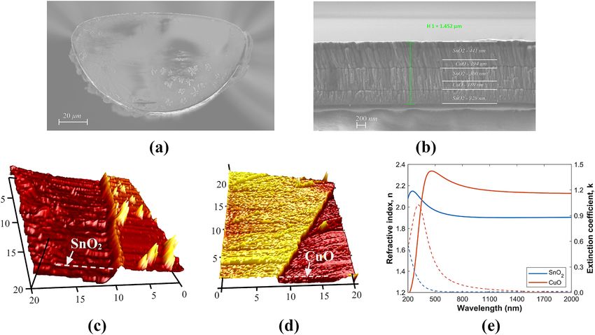
Figure 2. Dispersion curves of the core-guide mode and the BSW modes for the (a) 3-Layer, (b) 5-Layer, and
(c) 6-Layer 1DPC. The blue lines (right axis) represent the calculated transmission spectra, and the figure insets
are the 1DPC analyzed. (d) Optical field intensity distributions of the supported BSW modes for the analyzed
1DPCs. For the sake of simplicity, only the dispersion curves of the first 6 BSW modes are plotted.
the stack also determines the resonance width and depth depending on the material properties. From what we
learned from the 6-layer stack discussed above, we reduced the number of layers and included 3- and 5-layer
SnO2/CuO stacks in the study. To have better knowledge of the BSW excitation phenomenon in the D-shaped
fiber, theoretical simulations were performed using the commercial software package FIMMWAVE (details on
the parameters used for the simulations are given in the “Material and method” section).
Figure 2 shows the dispersion curves of the BSWs that can sustain the 3-, 5-, and 6-layer stacks designed in
the spectral range of interest, with the thickness and material of the termination layer being 245 nm (SnO2), 461
(SnO2), and 50 nm (CuO), respectively, as outlined in the insets (the thicknesses were chosen so that the spectral
position of the calculated spectra match with the experimental spectra, as will be shown later).
The phase matching conditions indicate that Bloch waves can be excited, and the power of the light can be
efficiently transferred from the fiber core to the few-layer 1DPC. The structure can guide a finite number of BSW
modes in a relatively narrow wavelength range. The number of guided modes, their transverse amplitude profiles
and their propagation constants depend on the cross-sectional structure of the multilayer and on the optical
frequency. In general, the resonance wavelength of a BSW mode of lower order occurs at a longer wavelength than
a BSW mode of high order. For instance, the phase matching points for the 3-layer 1DPC are at 1475.6 (BSW1),
1473 (BSW2), 1465.9 (BSW3), 1455.2 (BSW4), 1442.3 (BSW5), and 1427.7 nm (BSW6); for the 5-layer 1DPC at
1580.5 (BSW1), 1578.8 (BSW2), 1574.0 (BSW3), 1566.4 (BSW4), 1556.7 (BSW5), and 1545.7 nm (BSW6); and
for the 6-layer 1DPC at 1492.5 (BSW1), 1490.8 (BSW2), 1486.4 (BSW3), 1479.4 (BSW4), 1470.5 (BSW5), and
1460.0 nm (BSW6). It can be seen that the BSW phase-matching points of the 5- and 6-layer 1DPCs are closer
together and the associated loss peaks in their transmission spectra of the core-guided mode (blue lines) are
mostly caused by the attenuation bands of the surface modes BSW1 and BSW2 (for details see supplementary
material). On the other hand, the phase matching points of the 3-layer 1DPC are more separated, making the loss
peak in its transmission spectra wider since, in addition to the surface modes BSW1 and BSW2, the attenuation
band of the BSW3 mode now has a higher contribution and, therefore, a higher light transfer from the fiber core
to the 1DPC is observed in the transmission spectrum of the core-guided mode (see supplementary material).
The optical-field intensity distributions in Fig. 2 show that the fields are highly confined to the termination layer
Scientific Reports | (2021) 11:11266 | https://doi.org/10.1038/s41598-021-90504-z 4
Vol:.(1234567890)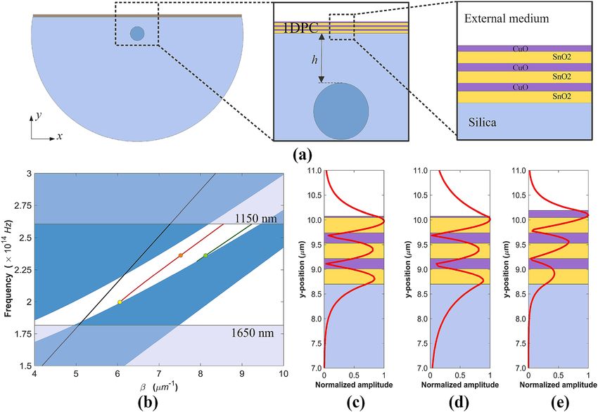
www.nature.com/scientificreports/

                                  Figure 3.  Characterization of coated D-shaped fiber with alternating layers of SnO2 and CuO using a DC
                                  sputtering system. SEM images of the (a) D-shaped fiber cross-section with 5-layer 1DPC; (b) detail of the
                                  deposited 5-layer SnO2/CuO 1DPC. AFM microscope images showing the roughness of the thin films deposited
                                  on coverslips for (c) SnO2 and (d) CuO, of 75 nm and 36 nm thickness, respectively. (e) Refractive index (solid
                                  lines) and extinction coefficient (dashed lines) of the SnO2 (blue) and CuO (red) thin films. (c-e) adapted with
                                  permission form Ref.45.

                                  and are concentrated within the 1DPC periods. This shows that 1DPCs can sustain different resonances depend-
                                  ing on the dielectric properties of the multilayer stack.

                                  Fabrication and device characterization. The three multilayer structures previously analyzed with the
                                  3-, 5-, and 6-layer 1DPCs were fabricated using alternating SnO2 and CuO on the flat surface of D-shaped
                                  standard fibers using a DC sputtering system (see “Materials and methods” section for more details). Note that
                                  in all cases, the first layer that is deposited on the flat surface of the D-shaped fiber is SnO2, whereby the 1DPC
                                  termination layer depends on the number of layers. As an example, a scanning electron microscopy (SEM)
                                  image of the cross-section of the D-shaped fiber with 5-layer 1DPC is shown in Fig. 3a. The characterization of
                                  the fiber shows that the distance between the core and the polished surface of the D-shaped fiber is h = 4.5 µm.
                                  The SEM image in Fig. 3b allows to differentiate the profile of the metal oxide depositions, where the two SnO2/
                                  CuO bi-layers can be clearly identified. From the analysis of the image it can be corroborated that the fabricated
                                  structure is very close to the designed multilayer stack of two SnO2/CuO bi-layers of 300/200 nm and a SnO2
                                  termination layer of 461 nm (see inset in Fig. 2). In addition, thin films of SnO2 and CuO deposited on coverslips
                                  placed at the same position of the fibers in the DC sputtering chamber were characterized with an atomic force
                                  microscope (AFM). A morphological study was performed in different zones in order to obtain the mean value
                                  of the film thickness and its surface roughness. The AFM images obtained are presented in Fig. 3c,d and show
                                  homogenous thin films of SnO2 and CuO with average RMS roughness 4.7 nm and 2 nm, respectively. Further-
                                  more, the thin films were also characterized with an ellipsometer to obtain the dispersion curves of the two
                                  materials. The wavelength dependence of the index of refraction and extinction coefficient of the SnO2 and CuO
                                  thin films can be seen in Fig. 3e. The high (low) refractive index of the CuO (SnO2) reveals the great potential
                                  of these metal oxides for the development of BSW platforms with moderate optical losses in the near-IR region
                                  of light. It is worth mentioning that in this work, extinction coefficient values of 0.01 for SnO2 and 0.02 for CuO
                                  were chosen to match with the experimental results. Here it is important to explain that the angle of incidence of
                                  the ellipsometer was set to 70◦ because more accurate results are obtained for angles approaching the Brewster
                                  angle, and this value is recommended by the manufacturer, Horiba, for the metallic oxides that we have used in
                                  the experiment. Oppositely, light is guided in the fiber at grazing incidence (90◦ ) related to the thin-film, which
                                  leads to a higher light scattering. This is not considered by the ellipsometer. Consequently, we attribute to this
                                  factor the discrepancy between the extinction coefficient calculated by the ellipsometer and the extinction coef-
                                  ficient required to fit the BSWs observed in the optical spectrum.
                                      After the 1DPCs were fabricated, the core-guided light transmission spectra were obtained as detailed in the
                                  “Materials and methods” section. The transmitted power is presented in Fig. 4 for the three multilayer structures

Scientific Reports |   (2021) 11:11266 |               https://doi.org/10.1038/s41598-021-90504-z                                                   5

                                                                                                                                               Vol.:(0123456789)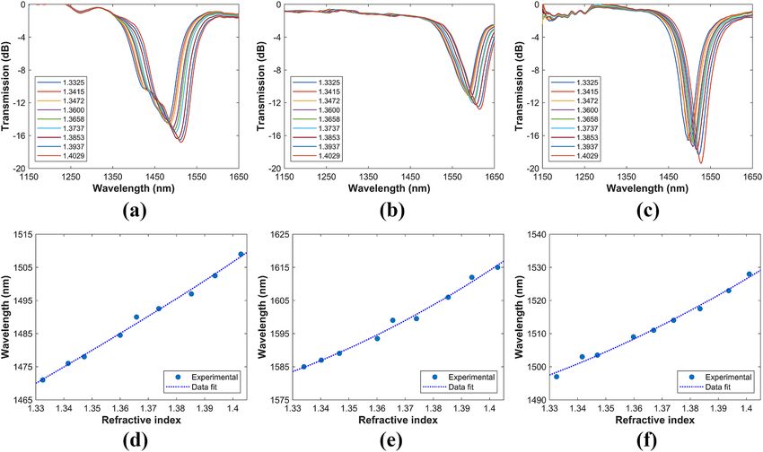
www.nature.com/scientificreports/
Figure 4. Transmission spectra of the coated D-shaped fibers. (a) 3-layer 1DPC, (b) 5-layer 1DPC, and (c)
6-layer 1DPC. The blue and red lines represent the experimental and the calculated spectra, respectively. The
external RI is 1.3325 (water).
when the surrounding medium is deionized ultrapure water (refractive index of 1.3325 at 1500 nm), measured
with a refractometer 30GS from Mettler Toledo Inc. Similarly, each device was analyzed numerically. Both
numerical and experimental results agree. As it was indicated previously, the generation of these resonances can
be explained by analyzing the dispersion curves in Fig. 2. Approximately at 1478, 1585 and 1496 nm, the surface
modes BSW1, BSW2 and BSW3 of each structure are excited by the evanescent field of the core-guided mode in
a relatively narrow wavelength range, which together with the moderate losses induced by the multilayer metal
oxides, consequently cause in the experimental transmission spectrum an attenuation peak in the BSW spectral
range. It is worth noting that the experimental results reveal that the effect of the BSW3 surface mode in the
case of the 3-layer stack is much greater than that predicted by the simulations and consequently the attenuation
peak is wider. This is confirmed by measuring the full width at half maximum (FWHM) of the experimental
attenuation peaks, which are 104.5 nm, 73.5 nm, and 52.5 nm, for 3-, 5- and 6-layer structures. Also, as more
layers are deposited, the spectral width of TE-BSW resonances tend to be narrower.
Characterization of the devices as refractometers. When the surrounding medium is changed,
the evanescent field of the BSW will be affected, and, thereby, the phase matching condition will be altered43.
In order to characterize the response of the devices presented in the previous section when they are used as
refractometers, their 1DPCs were immersed in nine refractive index (glycerol-water) solutions and the gener-
ated transmission spectra were captured. These spectra, represented in the top row of Fig. 5, confirm that the
BSWs generated by the SnO2/CuO multilayers are highly sensitive to surrounding RI index variations. It can be
appreciated that the BSW resonances shift to the red when they are subsequently immersed in solutions with
increasing RI value. The evolution of the central wavelengths of the attenuation peaks when the surrounding
RI is increased are presented in the bottom row of Fig. 5. As can be seen in these figures, the sensing response
exhibits a nonlinear feature, which is due to the wavelength-dependent mode coupling between the core-guided
mode and the BSW mode32,43.
Table 1 summarizes the refractometric response of the fabricated structures near to the surrounding RI nS =
1.33 and nS =1.40. The device sensitivity is defined as Sn = ∂ res /∂ns , where res is the central wavelength of the
attenuation peak. In addition, on the assumption that a 0.1 nm resolution detector is used, the sensor resolution
is defined as RES = 0.1/Sn58. The fabricated refractometric devices have comparable sensitivity to some ESW-
based sensing devices59,60, including some BSW-based structures33,61,62, for example, 631 nm/RIU in Ref.61, 285
nm/RIU in Ref.62 and -168 nm/RIU in Ref.33. On the other hand, our BSW-excitation platform has comparable
sensitivity with a tapered fiber coated with a 1DPC, which reports, respectively, 650 nm/RIU and 930 nm/RIU
for the TM and TE polarizations30.
Conclusion
In summary, we have proposed and experimentally demonstrated a novel BSW excitation platform based on
D-shaped optical fibers with few-layer 1DPC deposited on its flat surface using alternating thin layers of SnO2
and CuO. The fiber–optic-based platform enhances the light-matter interaction in a strong way compared to
other optical platforms, thereby decreasing the complexity and costs of manufacturing. In this platform, BSWs
can be efficiently excited through the evanescent field of the core-guided fundamental mode, resulting in a more
compact, lightweight and robust alternative compared to the Kretschman prism-based configuration.
To investigate the effect of the properties of the multilayer stack, 3-, 5-, and 6-layer 1DPCs were designed and
manufactured. Although most of the BSW excitation platforms require a large number of layers or materials with
a large difference in RI, we demonstrated that even a 3-layer stack on the fiber-based excitation platform can
sustain TE-polarized BSWs using a 1DPC consisting of materials that have a small difference in RI. Furthermore,
we demonstrated the suitability of this platform for measuring RI variations, paving the way for the development
of chemical sensors or biosensors. The proposed platform can be improved by selecting new materials, modify-
ing the thicknesses of the dielectric layers, or by modifying design parameters such as the depth of the polished
area, which can lead to sensors with higher sensitivities and resolutions.
Scientific Reports | (2021) 11:11266 | https://doi.org/10.1038/s41598-021-90504-z 6
Vol:.(1234567890)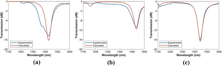
www.nature.com/scientificreports/
Figure 5. Characterization of the devices as refractometers. Experimental transmission spectra as function
of the surrounding RI: (a) 3-layer, (b) 5-layer, and (c) 6-layer 1DPC. Evolution of the corresponding central
wavelengths of the attenuation peaks: (d) 3-layer, (e) 5-layer and, (f) 6-layer 1DPC.
Surrounding RI Sensitivity (nm/RIU) Resolution (×10−4 RIU−1)
(RIU) 3-Layer 5-Layer 6-Layer 3-Layer 5-Layer 6-Layer
1.33 491 317 322 2.04 3.15 3.11
1.40 554 555 508 1.80 1.80 1.97
Table 1. Refractometric performance of the three fabricated structures based on few-layer 1DPC deposited on
D-shaped.
Finally, the simplicity of the designed 1DPC and the use of commercially available D-shaped fibers make it a
structure with broad development potential for new types of all-fiber photonic devices and sensing applications.
Materials and methods
The D-shaped fibers were supplied by the company Phoenix Photonics. They consisted of standard single mode
fiber (Corning SMF-28) with a side-polished length of 10 mm, and insertion losses of 4 dB at RI 1.45. The
D-shaped fibers were coated using DC sputtering system K675XD from Quorum Technologies, Ltd. The thin
films were deposited around the fiber, including the polished region, by using two different targets of tin oxide
SnO2, and copper oxide CuO (both of 57 mm in diameter and 3 mm in thickness). The CuO target was pur-
chased from ZhongNuo Advanced Material Technology Co, whereas the SnO2 target from Plasmaterials, Inc.
In addition, it is important to note that the tin oxide target was oxygen depleted and therefore strictly speaking
SnO2−x, although for the sake of simplicity we call it SnO2 throughout the article. The parameters used for the
DC sputtering depositions were argon partial pressure of 6 × 10⁻² mbar and an intensity of 90 mA.
The deposition process was carried out in short time intervals and was monitored in real-time by following
the spectral position of each resonance in the transmission spectra, using the setup schematized in Fig. 6a. A
broad-spectrum light source Agilent 83437A (1150–1680 nm) is connected to a linear polarizer and a polariza-
tion controller. The polarized light passes to the D-shaped fiber, which is located inside the sputtering chamber,
and the output is connected to an optical spectrum analyzer (OSA) Agilent 86142A. The polarization controller
allows to visualize the TE resonance in the optical spectrum. The position of the optical fiber was fixed inside
the sputtering machine, which included the two targets of SnO2 and CuO, programmed so that it is deposited
one thin film of SnO2 and one thin-film of CuO alternatively and progressively. After the coating process, the
fibers were removed from the sputtering machine and stored for a minimum of 48 h in air at 25◦ C before using
Scientific Reports | (2021) 11:11266 | https://doi.org/10.1038/s41598-021-90504-z 7
Vol.:(0123456789)www.nature.com/scientificreports/
Figure 6. (a) Schematic of the experimental setup used for the thin film deposition. To observe the evolution
of the optical spectrum during the thin film deposition, the pigtails connected to the polarization controller and
the optical spectrum analyzer enter the sputtering machine via feedthroughs. (b) Schematic of the experimental
setup used for the characterization of the devices as refractometers. The system allows controlling the
polarization of light in order to visualize the TE resonance in the optical spectrum.
them for refractive index measurements. The coated fibers were characterized as refractometers using the experi-
mental setup in Fig. 6b, for which they were immersed in refractive index solutions (glycerol-water) at different
concentrations and the corresponding transmission spectra were recorded. It is worth mentioning that, to avoid
distortion in the measurements, the fibers were carefully cleaned between measurements, since glycerol tends
to adhere to exposed surfaces.
The thin films of SnO2 and CuO deposited on coverslips where characterized with AFM microscopy (Bruker
Innova with RTESPA probes in tapping mode) and with a field emission scanning electron microscope (model
UltraPlus FESEM from Carl Zeiss Inc.) with an in-lens detector at 3 kV and an aperture diameter of 30 µm). The
metal oxide coatings were also characterized with an ellipsometer UVISEL 2 from Horiba, with spectral range
of 0.6-6.5 eV (190–2100 nm), an angle of incidence of 70◦ , a spot size of 1 mm and software DeltaPsi2TM (from
Horiba Scientific Thin Film Division). The thin films characterization was made on depositions over microscope
glass slides, as the flat surface of the D-shaped fiber (from Phoenix Photonic LTD) has a good finish comparable
to that of a coverslip. In Fig. 7, it is clear that the roughness is higher in the case of the D-shaped fiber, but it is
still a subnanometric value, indicating that the results of the coverslip can be extrapolated to the D-shaped fiber.
Finally, numerical simulations were calculated using the waveguide mode solver FIMMWAVE and the opti-
cal propagation tool FIMMPROP. The simulated structure begins with the light input SMF section, which is
analyzed with the finite difference method (FDM) because it is the most accurate method available for a cylin-
drical waveguide. In this section is adequate to find one propagating mode which corresponds to the fiber core
mode. Then the light reaches the segment of the side-polished fiber on which the thin layers of SnO2 and CuO
were deposited. This segment has a much more complex geometry, so it must be analyzed using the FEM Solver,
based on the finite element method. Due to the complexity of the structure, the number of modes analyzed in
this section is 20 to find the surface modes that match the core mode. Finally, the light reaches the light output
SMF, which is analyzed in the same way as the input section. The silica RI was calculated using the Sellmeier
equation with the coefficients reported in Ref.63, while its extinction coefficient was neglected. In addition, the
RI of SnO2 and CuO were taken from Fig. 3e while its extinction coefficients were taken as 0.01 for SnO2 and
0.02 for C uO50,51,64, to match with experimental results.
Scientific Reports | (2021) 11:11266 | https://doi.org/10.1038/s41598-021-90504-z 8
Vol:.(1234567890)www.nature.com/scientificreports/
Figure 7. AFM microscope images showing the roughness of (a) the coverslip and (b) the flat surface of a
D-shaped fiber sample (from Phoenix Photonic LTD). Homogeneous coverslip and D-shaped fiber surfaces are
observed with a mean RMS roughness of 0.204 nm and 0.365 nm, respectively.
Received: 30 October 2020; Accepted: 11 March 2021
References
1. Hu, D. J. J., Ho, H. P. & Day, R. M. Recent advances in plasmonic photonic crystal fibers: design, fabrication and applications. Adv.
Opt. Photonics 9, 257–314. https://doi.org/10.1364/AOP.9.000257 (2017).
2. Polo, J. A. & Lakhtakia, A. Surface electromagnetic waves: a review. Laser Photonics Rev. 5, 234–246. https://doi.org/10.1002/lpor.
200900050 (2011).
3. Sharma, A. K., Jha, R. & Gupta, B. D. Fiber-optic sensors based on surface plasmon resonance: a comprehensive review. Sens. J.
IEEE 7, 1118–1129. https://doi.org/10.1109/JSEN.2007.897946 (2007).
4. Polo, J. a., Mackay, T. G. & Lakhtakia, A. Electromagnetic Surface Waves: A Modern Perspective (Elsevier, 2013), 1st edn.
5. Deng, C. Z. et al. Two-pair multilayer Bloch surface wave platform in the near-and mid-infrared regions. Appl. Phys. Lett. 115,
https://doi.org/10.1063/1.5101008 (2019).
6. Kavokin, A. V., Shelykh, I. A. & Malpuech, G. Lossless interface modes at the boundary between two periodic dielectric structures.
Phys. Rev. Bhttps://doi.org/10.1103/PhysRevB.72.233102 (2005).
7. Consales, M., Pisco, M. & Cusano, A. Lab-on-fiber technology: a new avenue for optical nanosensors. Photonic Sens. 2, 289–314.
https://doi.org/10.1007/s13320-012-0095-y (2012).
8. Descrovi, E. et al. Near-field imaging of Bloch surface waves on silicon nitride one-dimensional photonic crystals. Opt. Express
16, 5453–5464. https://doi.org/10.1364/OE.16.005453 (2008).
9. Yeh, P., Yariv, A. & Cho, A. Y. Optical surface waves in periodic layered media. Appl. Phys. Lett. 32, 104–105. https://doi.org/10.
1063/1.89953 (1978).
10. Ballarini, M. et al. Bloch surface waves-controlled emission of organic dyes grafted on a one-dimensional photonic crystal. Appl.
Phys. Lett.https://doi.org/10.1063/1.3616144 (2011).
11. Joannopoulos, J. D., Johnson, S. G., Winn, J. N. & Meade, R. D. Photonic Crystals: Molding the Flow of Light (Princeton University
Press, 2008), 2nd edn.
12. Pirotta, S. et al. Strong coupling between excitons in organic semiconductors and Bloch surface waves. Appl. Phys. Lett. 104, 13–16.
https://doi.org/10.1063/1.4863853 (2014) arXiv:1312.7691.
13. Li, Y. et al. Phase-sensitive Bloch surface wave sensor based on variable angle spectroscopic ellipsometry. Opt. Express 22, 21403.
https://doi.org/10.1364/OE.22.021403 (2014).
14. Robertson, W. M. & May, M. S. Surface electromagnetic wave excitation on one-dimensional photonic band-gap arrays. Appl.
Phys. Lett. 74, 1800–1802. https://doi.org/10.1063/1.123090 (1999).
15. Sreekanth, K. V., Zeng, S., Shang, J., Yong, K.-T. & Yu, T. Excitation of surface electromagnetic waves in a graphene-based Bragg
grating. Sci. Rep. 2, 737. https://doi.org/10.1038/srep00737 (2012).
16. Dubey, R. et al. Experimental investigation of the propagation properties of bloch surface waves on dielectric multilayer platform.
J. Eur. Opt. Soc. 13, 9. https://doi.org/10.1186/s41476-016-0029-1 (2017).
17. Aurelio, D. & Liscidini, M. Electromagnetic field enhancement in Bloch surface waves. Phys. Rev. B 96, 1–7. https://doi.org/10.
1103/PhysRevB.96.045308 (2017) arXiv:1707.02111.
18. Kovalevich, T. et al. Polarization controlled directional propagation of Bloch surface wave. Opt. Express 25, 5710–5715. https://
doi.org/10.1364/OE.25.005710 (2017).
19. Scaravilli, M. et al. Excitation of Bloch surface waves on an optical fiber tip. Adv. Opt. Mater. 6, 1–10. https://d
oi.o
rg/1 0.1 002/a dom.
201800477 (2018).
20. Descrovi, E. et al. Guided Bloch surface waves on ultrathin polymeric ridges. Nano Lett. 10, 2087–2091. https://doi.org/10.1021/
nl100481q (2010).
21. Kong, W., Zheng, Z., Wan, Y., Li, S. & Liu, J. High-sensitivity sensing based on intensity-interrogated Bloch surface wave sensors.
Sens. Actuators B Chem. 193, 467–471. https://doi.org/10.1016/j.snb.2013.11.101 (2014).
22. Roussey, M. et al. One-dimensional photonic crystals with cylindrical geometry. Opt. Express 22, 27236–27241. https://doi.org/
10.1364/oe.22.027236 (2014).
23. Li, S. et al. Highly sensitive, Bloch surface wave D-type fiber sensor. IEEE Sens. J. 16, 1200–1204. https://doi.org/10.1109/JSEN.
2015.2498947 (2016).
24. Wang, R. et al. Bloch surface waves confined in one dimension with a single polymeric nanofibre. Nat. Commun. 8, 1–10. https://
doi.org/10.1038/ncomms14330 (2017).
25. Koju, V. & Robertson, W. M. Leaky Bloch-like surface waves in the radiation-continuum for sensitivity enhanced biosensors via
azimuthal interrogation. Sci. Rep. 7, 1–7. https://doi.org/10.1038/s41598-017-03515-0 (2017).
Scientific Reports | (2021) 11:11266 | https://doi.org/10.1038/s41598-021-90504-z 9
Vol.:(0123456789)www.nature.com/scientificreports/
26. Paeder, V., Musi, V., Hvozdara, L., Herminjard, S. & Herzig, H. P. Detection of protein aggregation with a Bloch surface wave based
sensor. Sens. Actuators B Chem. 157, 260–264. https://doi.org/10.1016/j.snb.2011.03.060 (2011).
27. Sinibaldi, A. et al. Direct comparison of the performance of Bloch surface wave and surface plasmon polariton sensors. Sens.
Actuators B Chem. 174, 292–298. https://doi.org/10.1016/j.snb.2012.07.015 (2012).
28. Sinibaldi, A. et al. A full ellipsometric approach to optical sensing with Bloch surface waves on photonic crystals. Opt. Express 21,
23331. https://doi.org/10.1364/oe.21.023331 (2013).
29. Frascella, F. et al. A fluorescent one-dimensional photonic crystal for label-free biosensing based on Bloch surface waves. Sensors
13, 2011–2022. https://doi.org/10.3390/s130202011 (2013).
30. Tu, T. et al. Excitation of Bloch surface wave on tapered fiber coated with one-dimensional photonic crystal for refractive index
sensing. Opt. Express 25, 9019–9027. https://doi.org/10.1364/OE.25.009019 (2017).
31. Liscidini, M. & Sipe, J. E. Enhancement of diffraction for biosensing applications via Bloch surface waves. Appl. Phys. Lett.https://
doi.org/10.1063/1.2826545 (2007).
32. Gonzalez-Valencia, E., Acuna Herrera, R. & Torres, P. Bloch surface wave resonance in photonic crystal fibers: towards ultra-wide
range refractive index sensors. Opt. Express 27, 8236–8245. https://doi.org/10.1364/OE.27.008236 (2019).
33. Gryga, M. et al. One-dimensional photonic crystal for Bloch surface waves and radiation modes-based sensing. Opt. Mater. Express
9, 4009. https://doi.org/10.1364/ome.9.004009 (2019).
34. Liscidini, M., Gerace, D., Sanvitto, D. & Bajoni, D. Guided Bloch surface wave polaritons. Appl. Phys. Lett.https://d oi.o
rg/1 0.1 063/1.
3571285 (2011).
35. Villa, F., Regalado, L. E., Ramos-Mendieta, F., Gaspar-Armenta, J. & Lopez-Ríos, T. Photonic crystal sensor based on surface waves
for thin-film characterization. Opt. Lett. 27, 646–648. https://doi.org/10.1364/OL.27.000646 (2002).
36. Delfan, A., Liscidini, M. & Sipe, J. E. Surface enhanced Raman scattering in the presence of multilayer dielectric structures. J. Opt.
Soc. Am. B 29, 1863. https://doi.org/10.1364/josab.29.001863 (2012).
37. Pirotta, S. et al. Surface-enhanced raman scattering in purely dielectric structures via bloch surface waves. J. Phys. Chem. C 117,
6821–6825. https://doi.org/10.1021/jp400223f7 (2013).
38. Toma, K. et al. Bloch surface wave-enhanced fluorescence biosensor. Biosens. Bioelectron. 43, 108–114. https://doi.org/10.1016/j.
bios.2012.12.001 (2013).
39. Angelini, A. et al. Fluorescence diffraction assisted by Bloch surface waves on a one-dimensional photonic crystal. N. J. Phys.https://
doi.org/10.1088/1367-2630/15/7/073002 (2013).
40. Frascella, F. et al. Enhanced fluorescence detection of miRNA-16 on a photonic crystal. Analyst 140, 5459–5463. https://doi.org/
10.1039/c5an00889a (2015).
41. Soljačić, M. & Joannopoulos, J. D. Enhancement of nonlinear effects using photonic crystals. Nat. Mater. 3, 211–219. https://doi.
org/10.1038/nmat1097 (2004).
42. Inoue, K., Oda, H., Ikeda, N. & Asakawa, K. Enhanced third-order nonlinear effects in slow-light photonic-crystal slab waveguides
of line-defect. Opt. Express 17, 7206–7216. https://doi.org/10.1364/oe.17.007206 (2009).
43. Gonzalez-Valencia, E., Del Villar, I. & Torres, P. Bloch waves at the surface of a single-layer coating D-shaped photonic crystal
fiber. Opt. Lett. 45, 2547–2550. https://doi.org/10.1364/OL.391508 (2020).
44. Fuentes, O. et al. Improving the width of lossy mode resonances in a reflection configuration D-shaped fiber by nanocoating laser
ablation. Opt. Lett. 45, 4738. https://doi.org/10.1364/ol.402177 (2020).
45. Fuentes, O. et al. Generation of lossy mode resonances with different nanocoatings deposited on coverslips. Opt. Express 28, 288.
https://doi.org/10.1364/oe.28.000288 (2020).
46. Tian, M., Lu, P., Chen, L., Lv, C. & Liu, D. All-solid D-shaped photonic fiber sensor based on surface plasmon resonance. Opt.
Commun. 285, 1550–1554. https://doi.org/10.1016/j.optcom.2011.11.104 (2012).
47. Markos, D. J. et al. Controlled core removal from a D-shaped optical fiber. Appl. Opt. 42, 7121. https://doi.org/10.1364/ao.42.
007121 (2003).
48. Kim, H. J., Kown, O. J., Lee, S. B. & Han, Y. G. Measurement of temperature and refractive index based on surface long-period
gratings deposited onto a D-shaped photonic crystal fiber. Appl. Phys. B Lasers Opt. 102, 81–85. https://doi.org/10.1007/s00340-
010-4146-z (2011).
49. Fuentes, O., Del Villar, I., Corres, J. M. & Matias, I. R. Lossy mode resonance sensors based on lateral light incidence in nanocoated
planar waveguides. Sci. Rep. 9, 1–10. https://doi.org/10.1038/s41598-019-45285-x (2019).
50. Del Villar, I., Zubiate, P., Zamarreño, C. R., Arregui, F. J. & Matias, I. R. Optimization in nanocoated D-shaped optical fiber sensors.
Opt. Express 25, 10743–10756. https://doi.org/10.1364/oe.25.010743 (2017).
51. Del Villar, I. et al. Optical sensors based on lossy-mode resonances. Sens. Actuators B Chem. 240, 174–185. https://doi.org/10.
1016/j.snb.2016.08.126 (2017).
52. Socorro-Leránoz, A., Santano, D., Del Villar, I. & Matias, I. Trends in the design of wavelength-based optical fibre biosensors
(2008–2018). Biosens. Bioelectron. Xhttps://doi.org/10.1016/j.biosx.2019.100015 (2019).
53. Yeh, P., Yariv, A. & Hong, C.-S. Electromagnetic propagation in periodic stratified media. I. General theory. J. Opt. Soc. Am. 67,
423–438. https://doi.org/10.1364/JOSA.67.000423 (1977).
54. Gaspar-Armenta, J. A., Villa, F. & López-Ríos, T. Surface waves in finite one-dimensional photonic crystals: mode coupling. Opt.
Commun. 216, 379–384. https://doi.org/10.1016/S0030-4018(02)02361-1 (2003).
55. Gomez-Cardona, N., Reyes-Vera, E. & Torres, P. High sensitivity refractive index sensor based on the excitation of long-range
surface plasmon polaritons in H-shaped optical fiber. Sensors 20, 11. https://doi.org/10.3390/s20072111 (2020).
56. Berini, P. Plasmon-polariton modes guided by a metal film of finite width. Opt. Lett. 7, 329–335. https://doi.org/10.1364/ol.24.
001011 (2000).
57. Wang, W., Fu, C. & Tan, W. Thermal radiative properties of a photonic crystal structure sandwiched by SiC gratings. J. Quant.
Spectrosc. Radiat. Transf. 132, 36–42. https://doi.org/10.1016/j.jqsrt.2013.01.022 (2014).
58. Gómez Cardona, N. D., Reyes Vera, E. & Torres, P. Multi-plasmon resonances in microstructured optical fibers: extending the
detection range of SPR sensors and a multi-analyte sensing technique. IEEE Sens. J. 18, 7492–7498. https://doi.org/10.1109/JSEN.
2018.2861709 (2018).
59. Kashyap, R. & Nemova, G. Surface plasmon resonance-based fiber and planar waveguide sensors. J. Sens. 2009, 9. https://doi.org/
10.1155/2009/645162 (2009) arXiv:9605103.
60. Torres, V., Beruete, M., Sánchez, P. & Del Villar, I. Indium tin oxide refractometer in the visible and near infrared via lossy mode
and surface plasmon resonances with Kretschmann configuration. Appl. Phys. Lett.https://doi.org/10.1063/1.4941077 (2016).
61. Li, Y. et al. Phase properties of Bloch surface waves and their sensing applications. Appl. Phys. Lett. 103, https://doi.org/10.1063/1.
4816810 (2013).
62. Tan, X.-J. & Zhu, X.-S. Optical fiber sensor based on Bloch surface wave in photonic crystals. Opt. Express 24, 16016–16026. https://
doi.org/10.1364/OE.24.016016 (2016).
63. Saleh, B. E. A. & Teich, M. C. Fundamentals of photonics (Wiley, 2007).
64. Del Villar, I. et al. Design rules for lossy mode resonance based sensors. Appl. Opt. 51, 4298–4307. https://doi.org/10.1364/AO.51.
004298 (2012).
Scientific Reports | (2021) 11:11266 | https://doi.org/10.1038/s41598-021-90504-z 10
Vol:.(1234567890)www.nature.com/scientificreports/
Acknowledgements
E.G.V. acknowledges the support of COLCIENCIAS through the Doctoral Scholarship program.
Author contributions
P.T. and I.D.V. developed the concept presented in this paper. E.G.V. carried out the simulations, conducted the
experimental measurements and drafted the manuscript. P.T. and I.D.V. supervised the entire project, reviewed
the paper and made a critical revision. All authors read and approved the final manuscript.
Funding
Fundación para la Promoción de la Investigación y la Tecnología-Banco de la República of Colombia (Contract
202103); Universidad Nacional de Colombia (Hermes code 46509); Agencia Estatal de Investigación (AEI) and
Fondo Europeo de Desarrollo Regional (TEC2016-78047-R and PID2019-106231RB-I00).
Competing interests
The authors declare no competing interests.
Additional information
Supplementary Information The online version contains supplementary material available at (https://doi.org/
10.1038/s41598-021-90504-z).
Correspondence and requests for materials should be addressed to E.G.-V.
Reprints and permissions information is available at www.nature.com/reprints.
Publisher’s note Springer Nature remains neutral with regard to jurisdictional claims in published maps and
institutional affiliations.
Open Access This article is licensed under a Creative Commons Attribution 4.0 International
License, which permits use, sharing, adaptation, distribution and reproduction in any medium or
format, as long as you give appropriate credit to the original author(s) and the source, provide a link to the
Creative Commons licence, and indicate if changes were made. The images or other third party material in this
article are included in the article’s Creative Commons licence, unless indicated otherwise in a credit line to the
material. If material is not included in the article’s Creative Commons licence and your intended use is not
permitted by statutory regulation or exceeds the permitted use, you will need to obtain permission directly from
the copyright holder. To view a copy of this licence, visit http://creativecommons.org/licenses/by/4.0/.
© The Author(s) 2021
Scientific Reports | (2021) 11:11266 | https://doi.org/10.1038/s41598-021-90504-z 11
Vol.:(0123456789)You can also read