Operating instructions - SAM-1950 / SAM-3000
←
→
Page content transcription
If your browser does not render page correctly, please read the page content below

Operating instructions
                         SAM-1950 / SAM-3000
                         Language:                  English
                         Revision:                  Version 1.5
                         Issue:                     March 2022

          NOTE
          Read these operating instructions carefully before assembly,
          installation and implementation.
                                                    These operating instructions are also available as a digital document on:
MDZ_E_B_SAM-3000_1.5                                            www.cgs-company.de/downloads/MDZ_E_B_SAM-3000.pdf
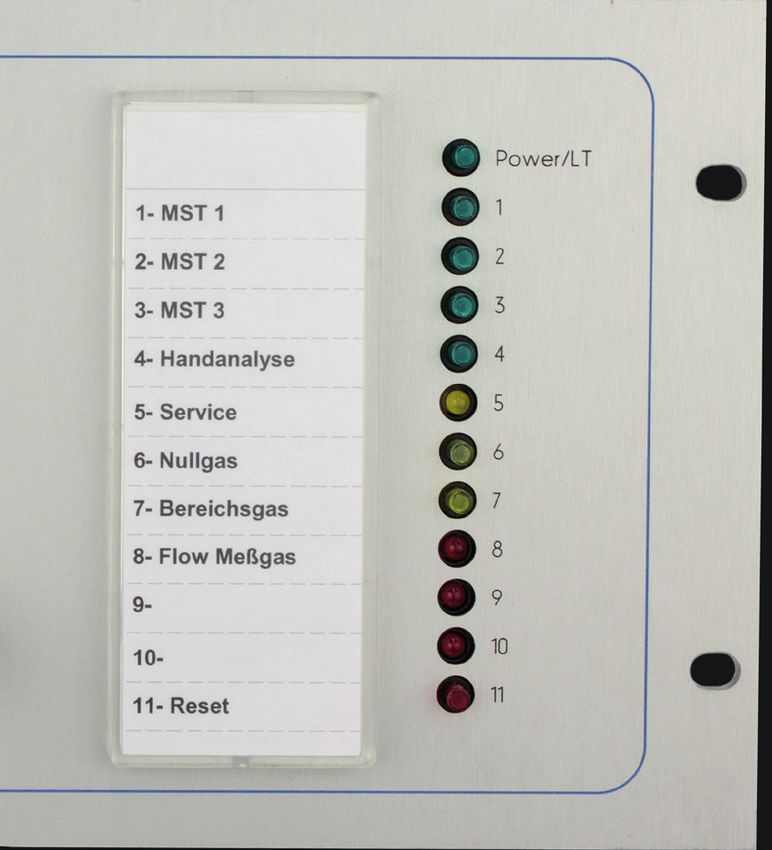
Table of contents
Table of contents. . . . . . . . . . . . . . . . . . . . . . . . . . . . . . . . . . . . . . . . . . . . . . . . . . . . . . . . . . . . . . . . . . . . .  3
1 General information. . . . . . . . . . . . . . . . . . . . . . . . . . . . . . . . . . . . . . . . . . . . . . . . . . . . . . . . . . . . . . . . .  5
       1.1 Device version and validity. . . . . . . . . . . . . . . . . . . . . . . . . . . . . . . . . . . . . . . . . . . . . . . . . . . . . .  5
       1.2 Information for our customers. . . . . . . . . . . . . . . . . . . . . . . . . . . . . . . . . . . . . . . . . . . . . . . . . . .  5
       1.3 General. . . . . . . . . . . . . . . . . . . . . . . . . . . . . . . . . . . . . . . . . . . . . . . . . . . . . . . . . . . . . . . . . . . . .  5
       1.4 Warnings and explanatory texts. . . . . . . . . . . . . . . . . . . . . . . . . . . . . . . . . . . . . . . . . . . . . . . . . .  5                          E
       1.5 Intended use. . . . . . . . . . . . . . . . . . . . . . . . . . . . . . . . . . . . . . . . . . . . . . . . . . . . . . . . . . . . . . . . .  6
       1.6 Qualified personnel. . . . . . . . . . . . . . . . . . . . . . . . . . . . . . . . . . . . . . . . . . . . . . . . . . . . . . . . . . . .  6
       1.7 Warranty information. . . . . . . . . . . . . . . . . . . . . . . . . . . . . . . . . . . . . . . . . . . . . . . . . . . . . . . . . .  6
       1.8 Delivery information. . . . . . . . . . . . . . . . . . . . . . . . . . . . . . . . . . . . . . . . . . . . . . . . . . . . . . . . . . .  7
       1.9 Norms and regulations . . . . . . . . . . . . . . . . . . . . . . . . . . . . . . . . . . . . . . . . . . . . . . . . . . . . . . . . .  7
       1.10 Disclaimer. . . . . . . . . . . . . . . . . . . . . . . . . . . . . . . . . . . . . . . . . . . . . . . . . . . . . . . . . . . . . . . . . .  8
       1.11 Disposal. . . . . . . . . . . . . . . . . . . . . . . . . . . . . . . . . . . . . . . . . . . . . . . . . . . . . . . . . . . . . . . . . . . .  8
2 Warnings and safety instructions. . . . . . . . . . . . . . . . . . . . . . . . . . . . . . . . . . . . . . . . . . . . . . . . . . . . . . .  9
3 Packaging and transport . . . . . . . . . . . . . . . . . . . . . . . . . . . . . . . . . . . . . . . . . . . . . . . . . . . . . . . . . . . .  10
       3.1 Packaging material. . . . . . . . . . . . . . . . . . . . . . . . . . . . . . . . . . . . . . . . . . . . . . . . . . . . . . . . . . .  10
       3.2 Shipping labels. . . . . . . . . . . . . . . . . . . . . . . . . . . . . . . . . . . . . . . . . . . . . . . . . . . . . . . . . . . . . .  10
       3.3 Transport inspection. . . . . . . . . . . . . . . . . . . . . . . . . . . . . . . . . . . . . . . . . . . . . . . . . . . . . . . . . .  11
       3.4 Storage . . . . . . . . . . . . . . . . . . . . . . . . . . . . . . . . . . . . . . . . . . . . . . . . . . . . . . . . . . . . . . . . . . . .  11
4 Installation, assembly information . . . . . . . . . . . . . . . . . . . . . . . . . . . . . . . . . . . . . . . . . . . . . . . . . . . .  12
5 Setup and function. . . . . . . . . . . . . . . . . . . . . . . . . . . . . . . . . . . . . . . . . . . . . . . . . . . . . . . . . . . . . . . . .  13
       5.1 Functional description. . . . . . . . . . . . . . . . . . . . . . . . . . . . . . . . . . . . . . . . . . . . . . . . . . . . . . . . .  13
       5.2 Design and operating mode. . . . . . . . . . . . . . . . . . . . . . . . . . . . . . . . . . . . . . . . . . . . . . . . . . . .  14
       5.3 Dimensional drawing. . . . . . . . . . . . . . . . . . . . . . . . . . . . . . . . . . . . . . . . . . . . . . . . . . . . . . . . .  15
       5.4 Gas flow schematic. . . . . . . . . . . . . . . . . . . . . . . . . . . . . . . . . . . . . . . . . . . . . . . . . . . . . . . . . . .  16
       5.5 Control PCB. . . . . . . . . . . . . . . . . . . . . . . . . . . . . . . . . . . . . . . . . . . . . . . . . . . . . . . . . . . . . . . . .  17
		             5.5.1 Design and operating mode of the control PCB with LED v.1.0. . . . . . . . . . . . . . . . . . . .  17
		             5.5.2 Design and operating mode of the control PCB with button v.2.0. . . . . . . . . . . . . . . . .  18
		             5.5.3 Design of both Control PCBs (back view) . . . . . . . . . . . . . . . . . . . . . . . . . . . . . . . . . . . .  19
       5.6. Design and functions of solenoid valve manifold. . . . . . . . . . . . . . . . . . . . . . . . . . . . . . . . . . .  23
		5.6.1 MVB-S. . . . . . . . . . . . . . . . . . . . . . . . . . . . . . . . . . . . . . . . . . . . . . . . . . . . . . . . . . . . . . . .  23
		5.6.2 MVB-K . . . . . . . . . . . . . . . . . . . . . . . . . . . . . . . . . . . . . . . . . . . . . . . . . . . . . . . . . . . . . . .  24
6 Connection options. . . . . . . . . . . . . . . . . . . . . . . . . . . . . . . . . . . . . . . . . . . . . . . . . . . . . . . . . . . . . . . . .  25
7 Technical data. . . . . . . . . . . . . . . . . . . . . . . . . . . . . . . . . . . . . . . . . . . . . . . . . . . . . . . . . . . . . . . . . . . . .  26
8 Maintenance & repair . . . . . . . . . . . . . . . . . . . . . . . . . . . . . . . . . . . . . . . . . . . . . . . . . . . . . . . . . . . . . .  27
       8.1 Replacing the solenoid valves / replacing the filter. . . . . . . . . . . . . . . . . . . . . . . . . . . . . . . . . .  27
9 Cleaning. . . . . . . . . . . . . . . . . . . . . . . . . . . . . . . . . . . . . . . . . . . . . . . . . . . . . . . . . . . . . . . . . . . . . . . . .  28
       9.1 Cleaning the surface. . . . . . . . . . . . . . . . . . . . . . . . . . . . . . . . . . . . . . . . . . . . . . . . . . . . . . . . . .  28
       9.2 Cleaning the interior. . . . . . . . . . . . . . . . . . . . . . . . . . . . . . . . . . . . . . . . . . . . . . . . . . . . . . . . . .  28
10 Device configuration (order code) . . . . . . . . . . . . . . . . . . . . . . . . . . . . . . . . . . . . . . . . . . . . . . . . . . . .  29
11 Delivery contents. . . . . . . . . . . . . . . . . . . . . . . . . . . . . . . . . . . . . . . . . . . . . . . . . . . . . . . . . . . . . . . . .  30
12 Spare parts. . . . . . . . . . . . . . . . . . . . . . . . . . . . . . . . . . . . . . . . . . . . . . . . . . . . . . . . . . . . . . . . . . . . . .  31
13 Appendix A (EU Declaration of Conformity). . . . . . . . . . . . . . . . . . . . . . . . . . . . . . . . . . . . . . . . . . . . .  33
14 Appendix B (Inspection protocols). . . . . . . . . . . . . . . . . . . . . . . . . . . . . . . . . . . . . . . . . . . . . . . . . . . .  35

Product:
SAM-3000 / SAM-1950                                                   Revision 1.5 – Issue March 2022                                                             3/38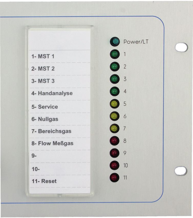
E

    Product:
    SAM-3000 /SAM-1950   Revision 1.5 – Issue March 2022   4/38
1 General information

1.1 Device version and validity
This documentation is restricted to the specified product and is only valid for this respective product. The
documentation describes the installation, implementation and maintenance of the device and provides
information about its function.
                                                                                                                        E
1.2 Information for our customers
Read this manual before commencing work on this device! It contains important information and data
that, when observed, will ensure the device functions properly and save service costs. Implementation
of this device is thereby considerably facilitated, leads to reliable measurement results and prevents
damage caused by improper use of the product.

1.3 General
This device has left the factory in a technically and operationally safe condition. To maintain this condition
and to ensure safe operation of this product, it must be implemented only in the manner specified by
the manufacturer. In addition, correct and safe operation of this product depends upon proper transport,
proper storage and installation as well as careful operation and maintenance.
This manual contains the information necessary for the proper use of the product described herein.
It is written for technically qualified personnel who are specially trained or have relevant knowledge in
the field of automation technology (measurement, control and feedback control systems).
Knowledge and technically correct implementation of the safety instructions and warnings contained in
this manual are required for the safe installation and implementation of the product described and for
its safety during operation and maintenance. Only qualified personnel have the necessary expertise to
interpret the generally applicable safety instructions and warnings in specific cases and to apply them in
practice.
This manual is an integral part of the scope of delivery even if a separate order is possible due to
logistical reasons.
Because of the large number of technical details, it is not possible to consider all the details for all
versions of the described product and for every conceivable installation, operation, maintenance and
implementation in systems.
If you need additional information, or should particular problems arise which are not sufficiently
covered in this document, please request the necessary information from your local or responsible CGS
representative.

1.4 Warnings and explanatory texts
This manual describes how you can properly run, commission, operate and maintain this device.
You must pay particular attention to all warning and explanatory texts. These are separated from the
text and specifically identified by the relevant icons. They provide you with valuable tips for avoiding
operating errors and accidents.

Product:
SAM-3000 / SAM-1950                              Revision 1.5 – Issue March 2022                                 5/38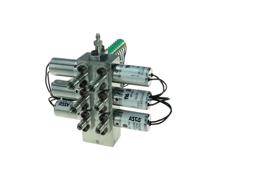
1.5 Intended use
    The intended use for the purposes of this manual means that this product must only be used for the
    applications described in the catalogue and in the technical description and only in conjunction with

E   external devices and components approved or recommended by CGS.
    The product described in this manual has been developed, manufactured, tested and documented in
    compliance with the applicable safety standards. No danger to personal health or property damage
    therefore normally ensues from compliance with the handling guidelines and safety instructions
    described for its project planning, assembly, intended use and maintenance.

    1.6 Qualified personnel
    Only those persons who are familiar with the installation, assembly, implementation and operation of
    the product are qualified.

    These persons have the following qualifications:
    • They are authorised, trained or instructed to operate and maintain equipment and systems in accordance
     with established safety procedures for electrical circuits, high pressures and aggressive and hazardous media.
    • For devices with explosion protection: They are authorised, trained or instructed in carrying out work on
     electrical circuits for hazardous systems.
    • They are trained or instructed in the maintenance and use of protective equipment in accordance with
     established safety procedures.

    1.7 Warranty information
    The contents of this manual is neither part of any previous or existing agreement, commitment or a
    previous or existing legal relationship, nor should anyone modify these. All obligations by CGS arise from
    the respective sales contract, which also contains the complete and solely applicable warranty terms and
    conditions.
    These contractual warranty regulations are neither extended nor limited by the contents of the manual.
    The manufacturer accepts no liability for damage or malfunctions resulting from failure to observe the
    operating instructions.
    Apart from the operating instructions and regulations regarding accident prevention applicable in the
    country and place of use, you must also observe the recognised technical regulations for safe and proper
    work.

    The warranty claim expires if the device is not installed, implemented, operated and maintained in
    accordance with regulations.

    Product:
    SAM-3000 /SAM-1950                               Revision 1.5 – Issue March 2022                                  6/38
Proper maintenance means:
• Adherence to the maintenance plan (see Chapter: Maintenance)
• Maintenance by trained maintenance personnel
E
• Use of original CGS spare parts
Maintenance should be performed by the CGS service technician or, on the operator side, by CGS-trained
service technicians.
The warranty is void in case of:
• improper use
• use of unauthorised equipment
• faulty connection and existing components that are not part of the scope of delivery and service
• failure to use original spare parts and accessories
• retrofitting that was not performed by
CGS itself
• non-compliance of prescribed maintenance work
The contents reflect the state of the art at the time of publication.
We reserve the right to make any technical changes due to further development.
1.8 Delivery information
The respective scope of delivery is listed in the shipping documents accompanying the delivery based
on the valid contract.
Please observe the corresponding information on the packaging material when opening the packaging.
Check the delivery for completeness and intactness. In particular, you should, where applicable, compare
the order number on the nameplates with the ordering data.
If possible, please keep the packaging materials so that you can use it for future return deliveries
(see Chapter: Packaging and transport).
1.9 Norms and regulations
The specification and production of this device were based on the harmonised European Norms whenever
possible. If no harmonized European Norms have been applied, then the norms and regulations of the
Federal Republic of Germany shall apply.
When using this product outside the scope of these norms and regulations, you must comply with the
norms and regulations valid in the operator's country.
Product:
SAM-3000 / SAM-1950 Revision 1.5 – Issue March 2022 7/38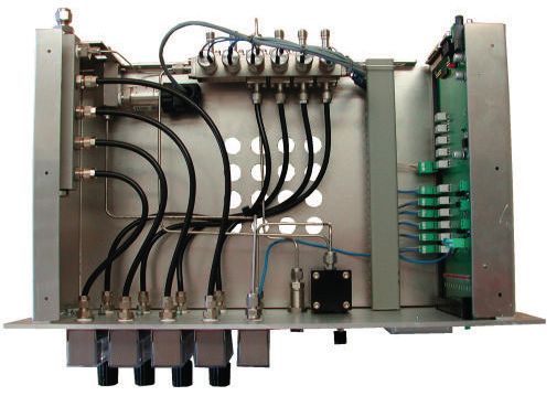
1.10 Disclaimer
    All technical information, data and operating instructions contained in this manual correspond to the
    latest state of development at the creation of this manual and are based on our previous experience and

E   knowledge to the best of our knowledge.

    We reserve the right to make any technical changes in the course of further development of the device
    described in these operating instructions. No claims can be derived from the data, illustrations and
    descriptions in this manual.

    We assume no liability for any damage and interruptions caused by operator error, non-observance of
    these operating instructions or improper repairs.

    We expressly state that only original spare parts and accessories approved by us must be used. This also
    applies to the subassemblies of other manufacturers.

    The installation or use of non-approved replacement parts and accessories and any unauthorised
    modifications and changes are not permitted for safety reasons and exclude liability by CGS for any resulting
    damages.

    Claims for damages are excluded regardless of the legal grounds of such claims.

    Translations are made in good faith. We cannot accept any liability for any translation errors not even
    when the translation was made by us or on our behalf. Only the original text is binding.

    The text and illustrations do not necessarily reflect the scope of delivery or a possible spare parts order.
    The drawings and diagrams are not to scale.

    1.11 Disposal

    This product comes from an environmentally conscious manufacturer and complies with the
    2012/19/EU directive on waste electrical and electronic equipment (WEEE).
    This product may contain substances which, if improperly disposed of (landfills, incinerators), are
    potentially environmentally harmful. It must therefore not be disposed of in this way.
    Therefore, behave environmentally conscious:
    • Arrange for this product to be recycled at the end of its life cycle via the relevant on-site facilities!
    • Observe the relevant regulations for your country!

    Product:
    SAM-3000 /SAM-1950                               Revision 1.5 – Issue March 2022                                8/38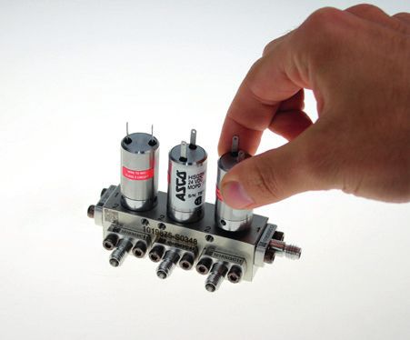
2 Warnings and safety instructions

This manual contains important Warnings and safety instructions which you must observe to ensure
your own personal safety and to avoid property damage. The instructions referring to your personal safe-
ty are indicated by a warning symbol. Instructions referring only to property damage have no warning

                                                                                                                  E
symbol. Depending on the hazard level, warnings are displayed in descending order as follows.

DANGER
indicates that death or severe personal injury will result if no appropriate precautions are taken.

WARNING
indicates that death or severe personal injury can result if no appropriate precautions are taken.

CAUTION
with warning triangle indicates that minor personal injury can result if no appropriate precautions are
taken.

CAUTION
without warning triangle indicates that property damage can result if no appropriate precautions are
taken.

NOTE
means that an undesirable event or situation can occur if the corresponding information is not observed.

If more than one hazard level occurs then the warning representing the highest degree of danger will be
used. If a warning triangle is used to warn against personal injury then the same warning can be added
to warn against property damage.

Product:
SAM-3000 / SAM-1950                            Revision 1.5 – Issue March 2022                             9/38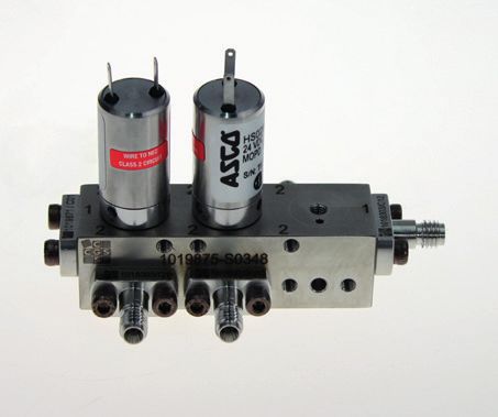
3 Packaging and transport
    3.1 Packaging material
    The individual system components and modules are shipped in different packaging. Primary packaging
    materials: wood, cardboard and plastics (films, foams), but also including hoop iron (for bundles), for
    example. Packing materials include materials which are added to the packages for moisture protection

E   (e.g. silica gel bags).
    If no agreement was reached on returning the packaging material then the packaging material remains
    with the customer.
    Waste disposal that is environmentally friendly and in accordance with the applicable disposal regulations
    must be ensured. If necessary, assign waste disposal companies with the disposal of the packaging
    material.
    The system components are to be transported as far as possible in the package to the installation site
    and kept in the package until assembly.

    3.2 Shipping labels

    Symbols are attached on the packages which must be observed during all transport phases including
    storage.

    1. TOP! The package must be stored, handled and transported in such a way that the arrows always point
    upwards. Rolling, swinging, severe tipping or walking of goods marked in this way must be avoided.

    2. Do not use forklift truck here

    3. Do not destroy barrier!

    4. Fragile, handle with care! Goods marked with this symbol should be handled carefully and should
    never be rolled over or tied tightly.

    5. Keep dry. Since goods of this type should also be protected from high levels of humidity, they must be
    transported in closed vehicles or containers.

    6. Center of gravity. This symbol is intended to provide a clear indication of the position of the center of
    gravity.

    Product:
    SAM-3000 /SAM-1950                              Revision 1.5 – Issue March 2022                                10/38
3.3 Transport inspection
Important:
Check the entire shipment for completeness and possible transport damage immediately upon arrival.
Failure to observe the following instructions in the event of damage shall cease the obligation of the
insurer to render performance.
• Even in case of suspected damage: Only acknowledge receipt with reservation (e.g. including shipping
documents) by specifying the alleged damage.
E
• Assert claims for compensation against third parties:
Carriers, freight forwarders, warehouse keepers:
- demand joint damage inspection
- request a certificate of damage
- hold these liable for damages in writing and describe the damage in detail,
namely:
- in case of visible damage prior to accepting delivery of the goods
- in case of no apparent outward damage immediately upon discovery
• Set deadlines for complaints and observe these!
• Ensure mitigation of incurred damage and avoidance of further damage.
• Immediately consult an insurance adjuster to record the damage and provide advice for securing claims
against third parties and for measures to mitigate the damage incurred.
• Never change the status of the consignment and its packaging until the arrival of the adjuster insofar
this is not required to mitigate and prevent further damage.
• Immediately notify the insurer about the insurance case and quickly submit the complete claim
documents to accelerate claims settlement (latest time before any preclusion and/or limitation periods
for claims against third parties).
3.4 Storage
After unloading, the packages must be stored until installation in accordance with the shipping markings.
Packed machine parts and accessories may not be unpacked.
Observe the applicable regulations for storage:
• Store in a cool dry place. Maximum humidity: 60 %.
Make sure the packages are not stored outdoors.
Also ensure that the storage room floor is dry during storage.
• Protect against direct sunlight. Storage temperature 5° C to 35 °C.
• Store in a dust-free location!
• Avoid mechanical shock and damage.
• For longer storage over 3 months, check the conservation measures.
In case of aggressive weather conditions, conservation must be renewed if necessary.
Product:
SAM-3000 / SAM-1950 Revision 1.5 – Issue March 2022 11/384 Installation, assembly information
Safety measures:
Installation and assembly must only be performed by specially trained and qualified personnel. The
E general accident prevention regulations must thereby be observed.
A formal handover to the operator occurs in case of implementation by CGS or its authorised representatives.
The device can subsequently be properly operated according to the operating instructions and applicable
safety regulations.
Before opening the device, disconnect it from the power supply in any case.
Requirements for the installation site:
• No exposure to direct sunlight
• Low exposure to dust
• Sufficient space for operation and maintenance
• Available and easily accessible escape routes
• No tripping hazards caused by cables that run close to the ground, etc.
• Maximum height: 2000 m above sea level
Technical prerequisites (supply voltage, gas pressures, etc.) can be found in the Technical Data section.
Product:
SAM-3000 /SAM-1950 Revision 1.5 – Issue March 2022 12/385 Setup and function
5.1 Functional description
The cabinet sample module series SAM-1000_DP is used to connect different sample points to analysers.
Because of its modular design, it can be used for various applications in the chemical and petrochemical
industries for gaseous high-purity gases.
E
Special features:
The SAM-3000 especially distinguishes itself through the following features:
• Compact construction
• Minor dead volume
• Modular configuration
• High leak thightness
• Multi-purpose applications possible
• PROFIBUS connectivity possible (optional)
Depending on the expansion stage of SAM-3000 can be switched up to 4 sample gases and 2 calibration
gases to an analyzer. For monitoring the gas ways at a glance LED’s shows the selected way. The LED’s
can be optionally arranged as Pushbuttons. Filter frits at the inlet of the switching module protects the
following analysers. So that impurities are filtered out of the sample gases and avoids pollutions and
damages at the analyzer. Filter frits are available in 20 μm and 50 μm fineness of filtration. With the
solenoid valve manifold concerning purging or no purging the dead volumes are minimized. For high pu-
rity applications the solenoid valves on the manifold are optimally arranged. By activation of a solenoid
valve a potential free contact can be used to send a feedback signal to the DCS. Up to 4 flow indicators
can be used to monitor the flow rate of sample gases. The SAM-3000 optional includes an integrated
pressure transmitter. The estimation of additional attended connectors and tubing connections can be
much reduced and supports a fast installation. A high variety of connectors can be chosen for different
tubing diameters. Depending on application different materials for the tubing inside of SAM-3000 can
be selected. Free configurable bridge circuits on control PCB compliance individual requirements. So for
e.g. the LED’s displays the individual task of function. Optionally the SAM-3000 can be connected to a
Profibus.
Product:
SAM-3000 / SAM-1950 Revision 1.5 – Issue March 2022 13/385.2 Design and operating mode
The SAM-3000 is designed as a plug-in module for 19“ racks or 19“ cabinets.
• Aluminium housing with mounted front plate
• Control PCB
• Solenoid valve manifold
E •
•
Outlet manifold
Depending on the expansion stage bulkhead unions, flow meters and flow regulators
Outlet to analyzer
Bypass-Outlet Pressure transmitter
Solenoid valve manifold
Housing with
front plate
Control PCB
Flow meters with
needle valve Flow low indicator Quick connector Flow controller
In the main case the inner of the module includes a solenoid valve manifold with selectable tubings in
different materials (metal, plastic or mixture of both) available. To control the solenoid valves and to
evaluate the signals is a control PCB integrated. The top of the LED’s the Pushbuttons are implemented in
the front plate of the SAM-3000. Depending on expansion stage there are bulkhead unions, flow meters
and flow regulators monted at the front plate.
Product:
SAM-3000 /SAM-1950 Revision 1.5 – Issue March 2022 14/385.3 Dimensional drawing
The following drawing shows the necessary space required:
E
SAM-3000
AP2615 Power/LT
bypass bypass bypass bypass sample
AP4711 AP4712 AP4713 AP4714 gas AP4711 Sample 1
AP4712 Sample 2
AP4713 Sample 3
AP4714 Sample 4
Service Service
Zero Gas Zero Gas
Span Gas Span Gas
25-250l/h
25-250l/h
25-250l/h
25-250l/h
Manual Flow 1
6-60l/h
Sample Flow 1
Sampling Flow
Flow 2 Flow 2
Flow 3 Flow 3
Flow 4 Flow 4
Blind plate Mounting plate
Product:
SAM-3000 / SAM-1950 Revision 1.5 – Issue March 2022 15/385.4 Gas flow schematic
A exemplary gas diagram is shown below:
example ATM
E
25-250 l/h
25-250 l/h
25-250 l/h
25-250 l/h
sample gas 1
sample gas 2
sample gas 3
sample gas 4
to analyser
6-60 l/h
zero gas
span gas
SAM-3000
Product:
SAM-3000 /SAM-1950 Revision 1.5 – Issue March 2022 16/385.5 Control PCB
The dimensions of control PCB is developed for using in the 19“plug-in device. Via guiding rails the con-
trol PCB gets through the module. On control PCB mounted diodes and Pushbuttons for inspection and
service are implemented in the front plate.
The connection plugs are located at the rear side of control PCB. Power supply plug, the connection to
analyzer and the plug for connection to the DCS. The control PCB is supplied by 24 V DC and protected by
a fuse. For a failure-free operation the voltage is stabilized onboard.
E
5.5.1 Design and operating mode of the control PCB with LED v.1.0
1
2
3
4
1 Pushbuttons
Used to test the lights on the front panel
2 Green LEDs to display sample gases
3 Yellow LEDs to display service, zero and span gas
4 Red LEDs for FLOW- Sample gas/ or. costomized display variants
Product:
SAM-3000 / SAM-1950 Revision 1.5 – Issue March 2022 17/385.5.2 Design and operating mode of the control PCB with
button v.2.0
E
1
2
3
4
5
6
7
1 Pushbuttons
Used to test the lights on the front panel
2
1 Pushbuttons for different sample gases
Switches the sample gases
1
3 LED for the service mode
1
4 Pushbutton for zero gas
1
5 Pushbutton for span gas
1
6 LED for FLOW- Sample gas/ or. costomized display variants
1
7 Pushbutton for Reset- Sample gas/ span gas
Product:
SAM-3000 /SAM-1950 Revision 1.5 – Issue March 2022 18/385.5.3 Design of both Control PCBs (back view)
1
2
E
3
4
1 Micro-fuse
2 Power supply 24 VDC
3 Connection to analyzer SUB-D 9-pin
4 Connection to DCS SUB-D 37-pin
Product:
SAM-3000 / SAM-1950 Revision 1.5 – Issue March 2022 19/38Description of display- and operating controls:
Power/LT (green):
LED is shining permanently, if the module is connected to the power supply. By pressing the button the
function of LEDs can be checked (all LEDs are shining).
E Sample 1 (green):
LED is shining permanently, if sample gas 1 is switched to the analyzer.
Sample 2 (green):
LED is shining permanently, if sample gas 2 is switched to the analyzer.
Sample 3 (green):
LED is shining permanently, if sample gas 3 is switched to the analyzer.
Sample 4 (green):
LED is shining permanently, if sample gas 4 is switched to the analyzer.
Service (yellow):
LED is shining permanently, if DCS releases manual service handling.
Zero Gas (yellow):
LED is shining permanently, if zero gas is switched to the analyzer.
Span Gas (yellow):
LED is shining permanently, if span gas is switched to the analyzer.
Flow 1 (red):
LED is shining by individual customer requirements. The LED can shine for instance if the gas flow of
sample gas 1 is in tolerance range or outside of tolerance range.
Flow 2 (red):
See above „Flow 1“.
Flow 3 (red):
See above „Flow 1“.
Flow 4 (red):
See above „Flow 1“.
Product:
SAM-3000 /SAM-1950 Revision 1.5 – Issue March 2022 20/38Plug connections:
Power supply (2-pin plug):
Pin Function Description
1 24 V DC voltage + 24 VDC
2 GND-connection GND
E
SUB-D 9-pin plug for connection to analyzer:
The left side „functions of device“ of diagram shows the schematic design of the control PCB.
The right side of diagram shows the connections to peripheral devices.
functions PIN-
of device assign
5 binary output service release
9 output GND
4 binary input flow
8 output 24VDC
3 binary input span gas
7 analog output pressure transmitter -
2 binary input zero gas
6 analog output pressure transmitter +
1 binary input sample gas 1
P
I
Product:
SAM-3000 / SAM-1950 Revision 1.5 – Issue March 2022 21/38Connection to DCS via a SUB-D 37-pin plug:
The left side „functions of device“ of diagram shows the schematic design of the control PCB.
The right side of diagram shows the connections to peripheral devices.
E functions
of device
PIN-
assign
19 contact sample gas 1.2
37 contact flow 4.2
18 contact sample gas 1.1
36 contact flow 4.1
17 nc
35 contact flow 3.2
16 nc
34 contact flow 3.1
15 nc
33 contact flow 2.2
14 nc
32 contact flow 2.1
13 nc
31 contact flow 1.2
12 nc
30 contact flow 1.1
11 binary input flow 4
29 contact span gas 1.2
10 binary input flow 3
28 contact span gas 1.1
9 binary input flow 2
27 contact zero gas 1.2
8 binary input flow 1
26 contact zero gas 1.1
7 binary input service release
25 contact sample gas 4.2
6 binary input span gas
24 contact sample gas 4.1
5 binary input zero gas
23 contact sample gas 3.2
4 binary input sample gas 4
22 contact sample gas 3.1
3 binary input sample gas 3
21 contact sample gas 2.2
2 binary input sample gas 2
20 contact sample gas 2.1
1 binary input sample gas 1
GND 24VDC
Product:
SAM-3000 /SAM-1950 Revision 1.5 – Issue March 2022 22/385.6. Design and functions of solenoid valve manifold
5.6.1 MVB-S
E
Solenoid valves
screwed in manifold
Solenoid valve
manifold (to analyzer)
Sample gas inlets
The standard solenoid valve block of 1.4305 is used for stream switching up to 10 different streams. It
has rapid switching solenoid valves, which have a very long life time – tested over 500 million switch-
ing operations. Due to the small design the solenoid valve block can be installed in an 19“-rack directly
behind the analyzer.
The connections for the individual sample gases and the calibration gases are made by flange adapt-
ers, which have integrated sinter metal filters. In addition the sample gas inlet can be equipped with a
continuously bypass to minimize the total response time. The valve block has a common tubule which
is connected to the analyzer. The other side of the tubule has a blind flange. Alternatively at low con-
centrations this flange will be changed by a capillary for a very low split flow.
Product:
SAM-3000 / SAM-1950 Revision 1.5 – Issue March 2022 23/385.6.2 MVB-K
Solenoid valve
E manifold (to analyzer)
Solenoid valves
screwed in manifold
Sample gas inlets
The standard solenoid valve block compact is a further development of the standard block. Due to the
new design the solenoid valves are mounted on opposite sides of the block. This reduces the length of
the block by half. The solenoid valve block can now be equipped with up to 20 gas inlets. New is also
the continuously purging of the solenoid valves. These rapid switching solenoid valves have a very
long life time – tested over 500 million switching operations. The connections for the individual sample
gases and the calibration gases are made by flange adapters, which have integrated sinter metal fil-
ters. In addition the sample gas inlet can be equipped with a continuously bypass to minimize the total
response time. The valve block has a common tubule which is connected to the analyzer. The other
side of the tubule has a blind flange. Alternatively at low concentrations this flange will be changed by
a capillary for a very low split flow.
Product:
SAM-3000 /SAM-1950 Revision 1.5 – Issue March 2022 24/38Measured value 4-20 mA
Measuring/Calibrating
Product:
Measuring/Calibrating
Selection measuring point Maintenance
Analyser
analogue
Maintenance messages Fault
Profibus
Analyser
Fault messages Measuring range identification
SAM-3000 / SAM-1950
Calibration
Measuring point
PCS
Test gas valves
3. Analyser with Profibus interface
1. Analyser without control function
Measuring gas valves
Service release
Test gas valves
Measuring gas valves
SAM-3000
Measuring gas flow alarm
6 Connection options
PCS Bypass flow alarm
4-20 mA
Test gas valve
Zero gas valve
Calibration
Bypass flow alarm
Measuring point valve
Measuring/Calibrating
Measuring gas flow alarm
Fault
Analyser
analogue
Maintenance
Measuring range identification
Revision 1.5 – Issue March 2022
PCS
2. Analyser with Autocal function
Test gas valve
Zero gas valve
Measuring gas valves
Service release
Controls
Measuring gas valves
Feedback
SAM-3000
Test gas valves
SAM-3000
Measured value
Measuring gas flow alarm
Bypass flow alarm
25/38
E7 Technical data
Inlets Quantity 1 ... 6
Inlet filter fineness without; 20 μm or 50 μm
Diameter (outer) 2 mm; 3 mm; 6 mm or 1/8“; 1/4“
Solenoid valves Standard 2/2-ways normally closed
Option 1 2/2-ways normally open
E Bypass
Option 2
Quantity
3/2-ways
1 ... 4
flow meters Flow rate variable 5-1200 l/h
Flow alarm Quantity 1 ... 4
Flow rate variable 5 - 1200 l/h
Flow Standard Needle valve
limitation Option Flow Controller 0 .. 96 l/h
Pressure Measuring range (Standard) 0 ... 1 bar
transmitter Output signal (Standard) 4 ... 20 mA
Materials All-wetted parts Stainless steel 1.4571 PTFE
Hounsing Aluminium, anodised
Interfaces DCS bit parallel SUB-D 37-pin
Optional PROFIBUS DPV2
Analyzer SUB-D 9-pin
Dimensions SAM-3000 483 x 4HU x 270 mm
SAM-1950 241,5 x 5HU x 270 mm
Weight By complete expansion stage approx. 7 kg
Electrical Power supply 24 V DC
connections Fuse M 1.6 A
Product:
SAM-3000 /SAM-1950 Revision 1.5 – Issue March 2022 26/388 Maintenance & repair
Maintenance or repair must only be performed by CGS service technicians. This can also be done by
CGS-instructed / trained technicians.
The warranty and liability expires in case of unauthorised maintenance or repair work.
E
The applicable safety and accident prevention regulations must be observed in any case.
8.1 Replacing the solenoid valves / replacing the filter
• To replace the solenoid valve, unscrew it using a hook spanner (Item No.: 1017105)
• O-ring (Item No.: 1026311) and the filter (Item No.: 1026309 (50µ)) are located on the bottom of the
connection
• To change the filter frits, loosen the Allen screws and remove the connection
• Remove the O-ring and take out the filter
• Before inserting the new filter and O-ring, clean the contact surfaces of the O-ring so that it can
properly seal.
Illustr. similar
Product:
SAM-3000 / SAM-1950 Revision 1.5 – Issue March 2022 27/389 Cleaning
9.1 Cleaning the surface
CAUTION
E Make absolutely sure that no water enters the device while cleaning.
Before cleaning the device, disconnect it from the power mains!
The front panels are washable. We recommend using a sponge or cloth soaked in a mild detergent.
9.2 Cleaning the interior
After opening the device, you can, if necessary, carefully blow out the interior with a compressed
air gun.
Product:
SAM-3000 /SAM-1950 Revision 1.5 – Issue March 2022 28/3810 Device configuration (order code)
SAM-1950-
SAM-3000- . . .
Gaseingänge / gas inlets
Anzahl der Eingänge / quantity of inlets 1
Anzahl der Eingänge / quantity of inlets 2
Anzahl der Eingänge / quantity of inlets 3
Anzahl der Eingänge / quantity of inlets 4
E
Anzahl der Eingänge / quantity of inlets 5
Anzahl der Eingänge / quantity of inlets 6
Kalibriergase / calibration gases
Anzahl / quantity 0
Anzahl / quantity 1
Anzahl / quantity 2
Eingangsfilter / inlet filter
Ohne Eingangsfilter / without inlet filter 0
Eingangsfilter 20µm / inlet filter 20µm 2
Eingangsfilter 50µm / inlet filter 50µm 5
Magnetventilausführung / solenoid valve design
Magnetventil STD / solenoid valve STD S
Magnetventil zur Feuchtemessung / solenoid valve for moisture analysis H
Magnetventil (NC) Anwendung im Sauerstoff / solenoid valve (NC) for oxygen application O
Magnetventil (NC) Anwendung im Sauerstoff zur Feuchtemessung / solenoid valve (NC) for
Y
moisture analysis and oxygen application
manueller Messeingang / manual measuring inlet
Ohne manuellen Messeingang / without manual measuring inlet 0
Manueller Messeingang / manual measuring inlet 1
Bypass-Durchflussmesser / bypass flow meter
Anzahl Bypass-Durchflussmesser / quantity of bypass flow meter 0
Anzahl Bypass-Durchflussmesser / quantity of bypass flow meter 1
Anzahl Bypass-Durchflussmesser / quantity of bypass flow meter 2
Anzahl Bypass-Durchflussmesser / quantity of bypass flow meter 3
Anzahl Bypass-Durchflussmesser / quantity of bypass flow meter 4
Messbereich Bypass-Durchflussmesser / measuring range bypass flow meter
Ohne / without 0
15 - 150 l/h A
25 - 250 l/h B
Andere / others C
Fluss- und Druckregelung / flow and pressure control
Ohne / without A
Durchflussregler 18l/h / flow controller 18l/h B
Durchflussregler 96l/h / flow controller 96l/h C
Durchflussregler in Edelstahl 96l/h / flow controller made of SS 96l/h D
Nadelventil / needle valve E
Druckminderer / pressure reducer F
Vordruckregler mit Durchflussmesser / back pressure regulator with flow meter H
Durchflussmesser für Messgas / flow meter for sample gas
Ohne Durchflussmesser / without flow meter 0
Durchflussmesser vor dem Analysator / flow meter before analyzer 1
Durchflussmesser mit Ringinitiator vor dem Analysator/ flow meter with ring initiator before analyzer 2
Durchflussmesser nach dem Analysator / flow meter after analyzer 3
Durchflussmesser mit Ringinitiator nach dem Analysator/ flow meter with ring initiator after analyzer 4
Messbereich Messgas-Durchflussmesser / measuring range sample gas flow meter
Ohne / without 0
0,5-5 l/h A
1,6-16 l/h B
6-60 l/h C
10-100 l/h D
2-20 l/h E
Andere / others X
Drucksensor / pressure sensor
Ohne Drucksensor / without pressure sensor 0
Drucksensor inkl. Verschraubung / pressure sensor incl. threaded connection 1
Kapillare / capillary
Ohne Kapillare / without capillary 0
Kapillare / capillary 1
Verrohrung Messgaseingang / piping sample gas input
Rohrdurchmesser Messgasanschluss 2mm / diameter for sample gas connection 2mm A
Rohrdurchmesser Messgasanschluss 3mm / diameter for sample gas connection 3mm B
Rohrdurchmesser Messgasanschluss 6mm / diameter for sample gas connection 6mm C
Rohrdurchmesser Messgasanschluss 1/8" / diameter for sample gas connection 1/8" E
Rohrdurchmesser Messgasanschluss 1/4" / diameter for sample gas connection 1/4" F
Verrohrung Kalibriergaseingang / piping calibration gas input
Rohrdurchmesser Kalibrieranschluss 2mm / diameter for calibration gas connection 2mm A
Rohrdurchmesser Kalibrieranschluss 3mm / diameter for calibration gas connection 3mm B
Rohrdurchmesser Kalibrieranschluss 6mm / diameter for calibration gas connection 6mm C
Rohrdurchmesser Kalibrieranschluss 1/8" / diameter for calibration gas connection 1/8" E
Rohrdurchmesser Kalibrieranschluss 1/4" / diameter for calibration gas connection 1/4" F
Ohne Kalibriergasanschluss / without calibration gas pipe W
Verrohrung Bypass / pipe design bypass
Verrohrung in Kunststoff 6mm / pipe design with plastic 6mm 1
Verrohrung in Edelstahl 6mm / pipe design with stainless steel 6mm 2
Ohne Bypass / without bypass 3
Ventilblock / valve block
MVB-S A
MVB-SP B
MVB-GC C
MVB-K D
MVB-KSP E
Steuerventile für Membranventile / pilot valves for membran valves F
Sonderversion / special version X
Aufbauvarianten / different assembly variations
Einfach-SAM / Single-SAM 1
Doppel-SAM / Double-SAM 2
1/2 - 19"-SAM (SAM-1950) 3
Sonderversion / special version S
LED Taster / LED push button
LED Anzeige V1 / LED indicator V1 A
LED Taster V2 / LED push button V2 B
Product:
SAM-3000 / SAM-1950 Revision 1.5 – Issue March 2022 29/3811 Delivery contents
Immediately after receipt, check whether the shipment has arrived complete and without damage.
• SAM-3000 / SAM-1950 [1x]
E
• Documentation [1x]
• Sub-D plug (9-pin) [1x]
• Sub-D plug (37-pin) [1x]
• Power plug (2-pin) [1x]
• Stainless steel nut + ferrule set [according to configuration]
Product:
SAM-3000 /SAM-1950 Revision 1.5 – Issue March 2022 30/3812 Spare parts
Pos *PU Article Order No.
1 1 pcs. Control and display board 1017998 (V1.0)
2 1 pcs. Control and display board with button 1018004 (V2.0)
3 1 pcs. Flow controller; 18 l/h; 1/8“; Alu-body; SS-diaphragm 1011221
4
5
1 pcs.
1 pcs.
Flow controller; 96 l/h; 1/8“; Alu-body; SS-diaphragm
Flow controller; 96l/h; 1/8“; SS-body; SS-diaphragm
1011223
1011224
E
Pressure Regulator with pressure gauge; Inlet: 20 bar; Outlet: 0.5 - 3
6 1 pcs. bar; NPT 1/4“ female; Chrome-plated brass; with Panel-Mounting- 1021835
Ring for SL 20-P
Flowmeter without valve; 10...100 Nl/h; without limit switch; nickel
7 1 pcs. 1028362
plated brass; 1/4“ NPT; Air
8 1 pcs. Ring sensor; inductive; NAMUR bistable; 10 mm 1014583
Pressure transmitter S-10; 0-25 bar; for general applications; stan-
9 1 pcs. 1019509
dard version
Solenoid valve; 2-ways; 24 VDC; D= 1.25mm; FKM; with connection
10 1 pcs. 1027695
cable 700mm
Solenoid valve; 3/2-ways; 24 VDC; D=1.25mm; with connection
11 1 pcs. 1019762
cable 300mm
Solenoid valve; O2; 2-way; 24 VDC; FKM; with connection
12 1 pcs. 1030682
cable 700 mm
Solenoid valve; O2; 2-way; 24 VDC; FKM; with connection
13 1 pcs. 1030686
cable 700 mm
Solenoid valve; O2; 3/2-ways; 24 VDC; with connection
14 1 pcs. 1030684
cable 300 mm
Solenoid valve; H2O; O2; 3/2-way; 24 VDC; with connection
15 1 pcs. 1030688
cable 300 mm
Solenoid valve; H2O; 2-ways; 24 VDC; D=1.25mm; with connection
16 1 pcs. 1024306
cable 700mm
Solenoid valve; 3/2-ways; 24 VDC; D=1.25mm; with connection
17 1 pcs. 1024308
cable 300mm
SS Integral Bonnet Needle Valve;Cv = 0.09; 3 mm Swagelok Tube
18 1 pcs. 1021802
Fitting; PCTFE Stem Tip
Flowmeter with needle valve; 25...250 Nl/h; without limit switch;
19 1 pcs. 1027287
nickel plated brass; 1/4“ NPT; Air
Pressure regulator GO; back pressure regulator; outlet: 3.5 bar; 50
20 1 pcs. 1019170
PSI; 3 x 1/4“ NPT
Flowmeter with needle valve; 15...150 Nl/h; without limit switch;
21 1 pcs. 1021111
nickel plated brass; 1/4“ NPT; Luft
22 1 pcs. O-ring set (10 pcs); FKM 6.00x2.00mm 1026311
23 1 pcs. Sintered metal frit set (10 pcs); D=6.35mm; pore size 50µ 1026309
24 1 pcs. Quick coupling plug; RBE 03; internal thread M8x1 1015026
25 1 pcs. Quick coupling plug; RBE 03; internal thread G 1/8 1015027
26 1 pcs. Tube fitting set 1/16“ SS 1027699
Product:
SAM-3000 / SAM-1950 Revision 1.5 – Issue March 2022 31/38Pos *PU Article Order No.
27 1 pcs. Tube fitting set 2 mm SS 1027700
28 1 pcs. Tube fitting set 1/8“ SS 1027701
E 29
30
1 pcs.
1 pcs.
Tube fitting set 3 mm SS
Tube fitting set 1/4“ SS
1027702
1027703
31 1 pcs. Tube fitting set 6 mm SS 1027704
32 1 pcs. Cap nut set 4.3 mm hose 1027705
33 1 pcs. Cap nut set 6 mm hose 1027706
34 1 pcs. Phillips-head screw set M6x16 with captive nuts 1027707
35 1 pcs. PTFE-hose; do=12.0 mm di=10.0 mm; nature 1015713
36 1 pcs. Hook spanner for screw in solenoid valve; DIN 1810 1017105
Pressure Regulator GO; Back Pressure Regulator; SBPR Series; Control
37 1 pcs. 1023812
Range 0 - 2.07 bar; 1/4“ NPT; stainless steel / Teflon
38 1 pcs. Fuse-links; 5x20mm ; 1,6 A; medium time-lag 1029869
*PU = Packing Unit
Product:
SAM-3000 /SAM-1950 Revision 1.5 – Issue March 2022 32/3813 Appendix A
(EU Declaration of Conformity)
EU-Konformitätserklärung
EU Declaration of Conformity
E
Hersteller/Manufacturer:
CGS Analysen-, Mess und Regeltechnik GmbH
Keltenstraße 3
85095 Denkendorf
Hiermit erklären wir, dass unser Produkt, Typ:
Hereby, we declare that the product, type:
SAM-1000*** / SAM-3000 / SAM-3500 / SAM-1950***
folgenden einschlägigen Bestimmungen entspricht:
is in conformity with the following applicable standards:
2014/35/EU Niederspannungsrichtlinie
Low Voltage Directive
2014/30/EU EMV-Richtlinie
EMC-Directive
2014/68/EU Druckgeräterichtlinie
Pressure Equipment Directive
Angewendete harmonisierte Normen, insbesondere:
Applied harmonised standards, especially:
DIN EN 61010-1:2020-03 Sicherheitsbestimmungen für elektrische Mess-, Steuer-, Regel-
(VDE 0411-1:2020-03) und Laborgeräte - Teil 1: Allgemeine Anforderungen
Safety requirements for electrical equipment for measurement, control and
laboratory use - Part 1: General requirements
DIN EN 61010-2-010:2015-05 Sicherheitsbestimmungen für elektrische Mess-, Steuer-, Regel-
(VDE 0411-2-010:2015-05) und Laborgeräte - Teil 2-010:
Besondere Anforderungen an Laborgeräte für das Erhitzen von
Stoffen
Safety requirements for electrical equipment for measurement, control and
laboratory use - Part 2-010: Particular requirements for laboratory equip-
ment for the heating of materials
DIN EN 61326-1:2013-07 Elektrische Mess-, Steuer-, Regel- und Laborgeräte
(VDE 0843-20-1:2013-07) EMV-Anforderungen - Teil 1: Allgemeine Anforderungen
Electrical equipment for measurement, control and laboratory use
EMC requirements - Part 1: General requirements
DIN EN 1779:1999-10 Zerstörungsfreie Prüfung - Dichtheitsprüfung - Kriterien zur Aus-
wahl von Prüfmethoden und -verfahren;
Non-destructive testing - Leak testing - Criteria for the method and
technique selection;
Denkendorf, den 13.07.2021
Jahreszahl der CE-Kennzeichenvergabe: 20
Alfons Geyer
Geschäftsführer / Managing director
Product:
SAM-3000 / SAM-1950 Revision 1.5 – Issue March 2022 33/38EU-Konformitätserklärung
E EU Declaration of Conformity
Hersteller/Manufacturer:
CGS Analysen-, Mess- und Regeltechnik GmbH
Keltenstraße 3
85095 Denkendorf
Hiermit erklären wir, dass unser Produkt, Typ:
Hereby, we declare that the product, type:
SAM-1950 / SAM-1950_DP
folgenden einschlägigen Bestimmungen entspricht:
is in conformity with the following applicable standards:
2014/35/EU Niederspannungsrichtlinie
Low Voltage Directive
2014/30/EU EMV-Richtlinie
EMC-Directive
2014/68/EU Druckgeräterichtlinie
Pressure Equipment Directive
Angewendete harmonisierte Normen, insbesondere:
Applied harmonised standards, especially:
DIN EN 61326-1:2013-07 Elektrische Mess-, Steuer-, Regel- und Laborgeräte
(VDE 0843-20-1:2013-07) EMV-Anforderungen - Teil 1: Allgemeine Anforderungen
Electrical equipment for measurement, control and laboratory use
EMC requirements - Part 1: General requirements
DIN EN 61010-1 Sicherheitsbestimmungen für elektrische Mess-, Steuer-, Regel-
(VDE 0411-1:2011-07) und Laborgeräte - Teil 1: Allgemeine Anforderungen
Safety requirements for electrical equipment for measurement, control and
laboratory use - Part 1: General requirements
DIN EN 61010-2-201:2014-01 Sicherheitsbestimmungen für elektrische Mess-, Steuer-, Regel-
(VDE 0411-2-201:2014-01) und Laborgeräte - Teil 2-201:
Besondere Anforderungen für Steuer- und Regelgeräte
Safety requirements for electrical equipment for measurement, control and
laboratory use - Part 2-201: Particular requirements for control equipment
DIN EN 1779:1999-10 Zerstörungsfreie Prüfung - Dichtheitsprüfung - Kriterien zur Aus-
wahl von Prüfmethoden und -verfahren
Non-destructive testing - Leak testing - Criteria for the method and
technique selection
Jahreszahl der CE-Kennzeichenvergabe: 12 Denkendorf, den 19.11.2020
Alfons Geyer
Geschäftsführer / Managing director
Product:
SAM-3000 /SAM-1950 Revision 1.5 – Issue March 2022 34/3814 Appendix B (Inspection protocols)
E
Qualitätszeugnis
Hiermit bestätigen wir, dass unsere Produkte nach aktuellem Stand der Technik produziert und
geprüft wurden.
Die verwendeten Materialien sind nach den Einsatzspezifikationen ausgesucht und nach
handwerklichen Richtlinien verarbeitet.
Hierbei kommen maßgebliche nationale und internationale Normen und Standards zur Anwendung.
Das fertige Produkt wurde nach technischen Gesichtspunkten in einem Qualitäts-
sicherungssystem geprüft und kontrolliert.
Quality certificate
Hereby we confirm that our products were produced and examined after
current state of the art.
The used materials were selected after
guidelines relating to crafts and processed according to the employment
specifications.
Here relevant national and international norms and
standard are used.
The finished product was examined and controlled in quality insurance system on
the basis of technical criteria.
Denkendorf, 29.09.2015
Alfons Geyer
Product:
SAM-3000 / SAM-1950 Revision 1.5 – Issue March 2022 35/38Prüfbescheinigung für Gaskomponenten in Sauerstoff
Inspection document for gas components in oxygen
E Hersteller:
manufacturer:
CGS Analysen-, Mess- und Verfahren:
method:
Nr.
no.
Regeltechnik GmbH
Keltenstraße 3 Reinigungsmethode: Ultraschallbad 1
cleaning method: ultrasonic bath
D-85095 Denkendorf
Aceton 2
acetone
Produktreihe: SAM-3000
product series: Spülen der Gaswege: Stickstoff 3
Gaskomponente: Sauerstoff purge of gas pathes: nitrogen
gas compontent: oxygen
Temperatur: ± 20°C 4
Anwendung: Gasanalyse / Sauerstoff temperature:
application: Öl- und Fettfrei
gas analysis / oxygen Trocknung: Stickstoffspülung 5
free of oil and grease drying: nitrogen purging
Drucktest: 3 bar (a) / 5 min. 6
pressure test:
1 bar (a) / 10 min. 7
Sauerstoffführende Komponenten:
oxygen transmitted components:
Bauteile: Verfahren:
components: method:
• Edelstahlrohr 2, 3, 4, 6
stainless steel tube
• Magnetventilblock 1, 3, 4, 5, 6
solenoid valve block
• Druckregler 3, 4, 5, 6/7
pressure regulator
• Manometer 3, 4, 5, 6/7
gauge
• Flow Controller 3, 4, 5, 6
flow controller
• Durchflussmesser 3, 4, 5, 6
flow meter
• Nadelventil 3, 4, 5, 6
needle valve
• Absperrventil 3, 4, 5, 7
ball valve
• Umschalthahn 3, 4, 5, 7
manifold valve
• Regulierventil 3, 4, 5, 6
control valve
• Rückschlagventil 1, 3, 4, 5, 6/7
check valve
• Überströmventil 3, 4, 5, 6/7
relief valve
• Verschraubungen 1, 3, 4, 5, 6
fittings
• Filterfritten für Magnetventilblock 3, 4, 5
filter frit for solenoid valve block
Denkendorf, 29.09.2015
Alfons Geyer
Product:
SAM-3000 /SAM-1950 Revision 1.5 – Issue March 2022 36/38E
Generelle Konformitätserklärung für Sauerstoffanwendungen
Für Komponenten und Systeme, die für Produktion, Lagerung und Transport von gasförmigem
Sauerstoff verwendet werden und mit ihm in Berührung kommen, ist eine extrem saubere
Oberfläche erforderlich.
CGS Analysen-, Mess- und Regeltechnik GmbH bestätigt, dass die gasführenden Bauteile unserer
Analysenanlagen für Sauerstoffanwendungen gemäß den aktuellen Vorschriften gebaut werden.
Somit sind die Werkstoffe für Druckregler, Rohr, Manometer… speziell gereinigt und mit Inertgas
gespült. Materialien sind frei von
- Fett, Öl und anderem organischen Material (Kohlenwasserstoffverbindungen)
- Wasser
- Lacken, Anstrichsystemen und anderen Beschichtungen
- losem Rost, Walzhaut, Füllmaterial, Schweißverfärbungen und Schweißspritzern.
General confirmation certification for oxygen applications
Components and systems used for production, storage and transportation of gaseous oxygen and
come into contact with, an extremely clean surface is required.
CGS Analysen-, Mess- und Regeltechnik GmbH confirms that gas-bearing components of your
analyzer systems for oxygen applications are build according to the current standard regulations.
Therefore the materials of pressure regulators, tubes, gauges… are special cleaned and inert gas-
purged. Materials are clear of
- grease, oil and other organic materials (hydrocarbon)
- water
- laquer, painting systems and other coatings
- loose rust, mill scale, filling material, sweat stains and spatters.
Denkendorf, 29.09.2015
Alfons Geyer
Product:
SAM-3000 / SAM-1950 Revision 1.5 – Issue March 2022 37/38CGS Analysen- Mess und Regeltechnik GmbH Keltenstraße 3 85095 Denkendorf Fon: +49 8466 9415-0 www.cgs-company.de
You can also read