Operator's Manual WYZ 48/52/60 - Zero Turn Mower - Worldlawn
←
→
Page content transcription
If your browser does not render page correctly, please read the page content below
Operator’s Manual
                                                R

                     WYZ 48/52/60
                     Zero Turn Mower

          Worldlawn Power Equipment, Inc.
Industrial Park 2415 Ashland Ave.   Beatrice, NE 68310
          Toll Free Number: 1-800-267-4255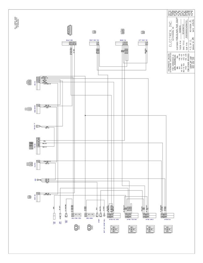

OPERATOR’S MANUAL
This manual contains assembly, operating, maintenance, adjustment, and safety instructions for your
WYZ 48/52/60 lawn mower.
Before operating your mower, read this manual in its entirety carefully.
By following the operating, maintenance, adjustment, and safety instructions, you will prolong the life of your
mower, maintain its maximum efficiency, and promote safe operation.
Keep this mower Owner’s Manual when lent or transferred.
If this mower Operator’s Manual becomes lost, damaged, or illegible, replace it immediately, replacements may
be ordered through our sales department. If additional information is needed, contact our sales department or a
dealer. Always give the model number and serial number.
To improve the quality, performance, and security of our products, we may make changes of our products.
Sorry for the inconvenience if you find the products in hand a bit different from the manual.

     POTENTIAL HAZARD
     ·This product is a piece of power equipment.
     WHAT CAN HAPPEN
     ·Failure to follow safe operating practices can result in serious operator injury or even death.
     HOW TO AVOID THE HAZARD
     ·Keep all shields, guards, and safety devices (especially the grass discharge system) in place and
     in proper working condition.
     ·Stop machine and wait for all moving parts to stop, remove spark plug wires or remove key
     before adjusting, servicing, or performing maintenance.
     ·If mower deck becomes clogged, stop machine and wait for all moving parts to stop. Remove
     spark plug wire or remove key before cleaning blockage.
     ·Keep hands, feet, and clothing away from power driven parts.
     ·Keep others off of mower.

     POTENTIAL HAZARD
     · Gasoline is harmful or fatal if swallowed. Long-term exposure of vapor causes cancer in
     laboratory animals.
     WHAT CAN HAPPEN
     ·Failure to use caution may cause serious injury or illness.
     HOW TO AVOID THE HAZARD
     ·Avoid prolonged breathing of vapor.
     ·Keep face away from nozzle and gas tank opening.
     ·Keep away from eyes and skin.
     ·Never siphon by mouth.
TABLE OF CONTENTS
1. SAFETY …………………………………………………………………………………                               1
  1.1 Safety Alert Symbol…………………………………………………………………                      1
  1.2 Training………………………………………………………………………………. 1
  1.3 Preparation ……………………………………………………………………….…                         1
  1.4 Operation ………………………………………………………………………...…                         3
  1.5 Maintenance & Storage …………………………………………………………...…                  5
  1.6 Safety Decals …………………………………………………………………...……                      6
2. SPECIFICATIONS………………………………………………………………………                            10
  2.1 Model Number………………………………………………………………………                           10
  2.2 Engine……………………………………………………………………………….                             10
  2.3 Fuel System………………………………………………………………………….                          10
  2.4 Electrical System…………………………………………………………………….                      10
  2.5 Operator Controls …………………………………………………………………..                     10
  2.6 Seat………………………………………………………………………………….                              11
  2.7 Hydrostatic Ground Drive System…………………………………………………..              11
  2.8 Tires And Wheels…………………………………………………………………...                      11
  2.9 Cutting Deck…………………………………………………………………………                          11
  2.10 Dimensions ………………………………………………………………………...                        12
  2.11 Torque Requirements………………………………………………………………..                    13
3. ASSEMBLY INSTRUCTIONS…………………………………………………………                          14
  3.1 Uncrate Mower………………………………………………………………………                          14
  3.2 Install Roller Protection System (Roll Bar) …………………………………..…..…   14
  3.3 Service Battery………………………………………………………………………                        15
  3.4 Install Drive Wheels And Check Tire Pressure…………………………………..…      16
  3.5 Install Seat……………………………………………………………………………                         16
  3.6 Install Motion Control Levers ……………………………………………………….              16
  3.7 Position Discharge Chute ……………………………………………………………                  17
  3.8 Service Engine……………………………………………………………………….                        17
  3.9 Service Hydraulic Oil………………………………………….…………………….                   17
4. OPERATION INSTRUCTIONS ………………………………….……………………                        18
  4.1 Controls………………………………………………………………………………                            18

4.2 Pre-Start…………………………………………………………………………….                20
  4.3 Mowing …………………………………………………………….………………                  20
  4.4 Transporting …………………………………………….……………………….…             22
5. MAINTENANCE & ADJUSTMENTS……………………………..……..……………           23
  5.1 Periodic Maintenance ………………………………………………………………          23
    5.2 Adjustments ………………………..………………..………………………………          29
    ………………………………………………………………..
6. TROUBLESHOOTING     ……………………………..…………………………………            34
7. HYDRAULIC DIAGRAM ……………………………………………………….……..              36
…………………………………………………….
    7.1 Hydraulic Pump Troubleshooting……………………………………………………   37
8. ELECTRICAL DIAGRAM……………………………………………………………… 38
 LIMITED WARRANTY …………………………………………………………………                  39
accessories and attachments are needed to properly
1. SAFETY and safely perform the job. Only use accessories and
1.1 SAFETY ALERT SYMBOL attachments approved by
Worldlawn Power Equipment, Inc.
This SAFETY ALERT SYMBOL is used 1.3.2 The use of personal protective gear, such as
both in this manual and on the machine to identify (but not limited to) protection for the eyes, ears, feet,
important safety messages which must be followed to and head are recommended.
avoid accidents. This symbol means:
ATTENTION! BECOME ALERT! POTENTIAL HAZARD
YOUR SAFETY IS INVOLVED! ·This machine produces sound levels in excess of
The safety alert symbol above alerts you to 85 dBA at the operator’s ear when in operation.
unsafe actions or situations by the word WHAT CAN HAPPEN
DANGER, WARNING, or CAUTION. ·Exposure to sound levels of 85dBA or above for
extended periods of time can cause hearing loss.
White letters on red background.
HOW TO AVOID THE HAZARD
Failure to observe the safety instructions could · Wear hearing protection when operating this
result in death or serious injury. machine.
1.3.3 While mowing, always wear proper
Black letters on orange background.
footwear and long trousers. Do not operate equipment
Failure to observe the safety instructions could when barefoot or when wearing open sandals.
result in death or serious injury. 1.3.4 Thoroughly inspect the area where the
equipment is to be used and remove all stones, sticks,
Black letters on yellow background.
wires, bones, and other foreign objects which may
Failure to observe the safety instructions may damage the equipment or cause personal injury to
result in slight or serious injury. operator or bystanders.
1.2 TRAINING POTENTIAL HAZARD
1.2.1 Regard the mower as a piece of power ·Engine exhaust contains carbon monoxide, which
equipment. The operator needs to be trained before is an odorless deadly poison.
operating this unit. WHAT CAN HAPPEN
1.2.2 Read the instructions carefully. Be ·Carbon monoxide can kill you.
thoroughly familiar with controls and the proper use HOW TO AVOID THE HAZARD
of the equipment. ·Do not run engine indoors or in a small confined
1.2.3 Never allow children, teenagers, or adults area where dangerous carbon monoxide fumes can
to operate the equipment without proper instruction. collect.
1.2.4 Keep everyone, especially children and pets,
away from the area of operation. Remember that the
operator or user is responsible for accidents or
hazards occurring to other people or their property.
1.3 PREPARATION
1.3.1 Evaluate the terrain to determine what
1POTENTIAL HAZARD POTENTIAL HAZARD
· In certain conditions gasoline is extremely · In certain conditions gasoline is extremely
flammable and highly explosive. flammable and highly explosive.
WHAT CAN HAPPEN WHAT CAN HAPPEN
·A fire or explosion from gasoline can burn you, ·A static charge can ignite gasoline vapors. A fire
others, and cause property damage. or explosion from gasoline can burn you, others,
HOW TO AVOID THE HAZARD and cause property damage.
·Do not smoke while refueling. Stay away from an HOW TO AVOID THE HAZARD
open flame or where gasoline fumes may be ·Purchase and store gasoline only in an approved
ignited by spark. container.
·Refuel only outdoors. ·Always place gasoline containers on the ground
·Store gasoline in an approved container and keep away from your vehicle while filling.
it out of the reach of children. ·Do not fill gasoline containers inside a vehicle or
·Add fuel before starting the engine. Never remove on a truck or trailer bed. Interior carpets or plastic
the cap of the fuel tank or add fuel when engine is truck bed liners may insulate the container and
running or when the engine is hot. slow the loss of any static charge.
·Never fill the fuel tank so that gasoline level rises ·When practical, remove gas-powered equipment
above a level that is 3/8"(10mm) below the from the truck or trailer and refuel the equipment
bottom of the filler neck. This allows for gasoline with its wheels on the ground.
expansion and prevents fuel spillage. ·If this is not possible, refuel such equipment on a
·If fuel is spilled, DO NOT attempt to start the truck or trailer from a portable container, rather
engine. Move away from the area of the spill. than from a gasoline dispenser nozzle.
Avoid creating any source of ignition until fuel ·If a gasoline dispenser nozzle must be used, keep
vapors have dissipated. the nozzle in contact with rim of the fuel tank or
·Do not operate without entire exhaust system in container opening at all times until fueling is
place and in proper working condition. complete.
2POTENTIAL HAZARD POTENTAL HAZARD
·Gasoline vapor can collect inside enclosed trailers · Operating engine parts, especially the muffler,
and may be ignited by electrical sparks or hot become extremely hot.
engine/exhaust components. WHAT CAN HAPPEN
WHAT CAN HAPPEN ·Severs burns can occur on contact.
· Explosion and fire may occur, resulting in ·Debris, such as leaves, grass, brush, etc. can catch
property damage, personal injury, and/or death. fire.
HOW TO AVOID THE HAZARD HOW TO AVOID THE HAZARD
· Provide adequate ventilation of any enclosed ·Allow engine parts, especially the muffler, to cool
trailer to prevent build up of gasoline vapors, before touching.
especially at floor level. ·Remove accumulated debris from muffler and engine
·Refuel only outdoors, never inside an enclosed area.
trailer. ·Install and maintain in working order a spark arrester
· Be sure all fuel tanks and gasoline storage before using equipment on forest-covered,
containers have proper caps installed to prevent grass-covered, or brush-covered unimproved land.
spillage and minimize vapor escaping into the
trailer.
· Do not place any equipment that is leaking POTENTIALHAZARD
gasoline in an enclosed trailer. · Hands, feet, hair, clothing, or accessories can
become entangled in rotating parts.
1.4 OPERATION WHAT CAN HAPPEN
Although hazard control and accident prevention · Contact with rotating parts can cause traumatic
partially are dependent upon the design and amputation or severe lacerations.
configuration of the equipment, these factors are also HOW TO AVOID THE HAZARD
dependent upon the awareness, concern, prudence, ·Do not operate the machine without guards, shields,
and proper training of the personnel involved in the and safety devices in place and working properly.
operation, transport, maintenance and the storage of ·Keep hands, feet, hair, jewelry, and clothing away
the equipment. It is essential that all Operator Safety from rotating parts.
Mechanisms be connected and in operating condition 1.4.1 Give complete, undivided attention to the
prior to use for mowing. job at hand.
1.4.2 Mow only in daylight or good artificial
light, keeping away from holes and hidden hazards.
NEVER carry passengers. DO NOT operate the
mower when children or others are in the area!
3POTENTIAL HAZARD
·Mowing on wet grass or steep slopes can cause
sliding and loss of control.
WHAT CAN HAPPEN
·Wheels dropping over edges, ditches, steep banks,
or water can cause rollovers, which may result in
serious injury, death or drowning. Danger
Safe
HOW TO AVOID THE HAZARD Water Zone Zone
·Do not mow on slopes when grass is wet.
·Do not mow near drop-offs or near water.
·Do not mow on slopes greater than 15 degrees.
·Reduce speed and use extreme caution on slopes. FIG 1
·Avoid sudden turns or rapid speed changes. SAFE ZONE FOR MOWING
Use a walk behind mower /or a hand trimmer 1.4.3 A Rollover Protection System (roll bar) is
near drop-offs, ditches, steep banks or water. This installed on the unit.
area can be dangerous, see Figure1.
Progressively greater care is needed as the slope POTENTIAL HAZARD
increases. ·There is no rollover protection when the roll bar is
Always avoid sudden starting or stopping on a down.
slope. If tires lose traction, disengage the blades WHAT CAN HAPPEN
and proceed slowly off the slope. ·Wheels dropping over edges, ditches, steep banks, or
Avoid sudden starts when mowing uphill. Mower water can cause rollovers, which may result in serious
may tip backwards. injury, death or drowning.
Be aware that loss of traction may occur going HOW TO AVOID THE HAZARD
downhill. Weight transfer to the front wheels may ·Keep the roll bar in the raised and locked position
cause drive wheels to slip and cause loss of and use seat belt.
braking and steering. ·Lower the roll bar only when absolutely necessary.
Watch for ditches, holes, rocks, dips, and rises ·Do not wear seat belt when the roll bar is down.
that change the operating angle, as rough terrain ·Drive slowly and carefully.
could overturn the machine. ·Raise the roll bar as soon as clearance permits.
Use extreme care with grass catchers or · Be certain that the seat belt can be released quickly
attachments. These can change the stability of the if the machine is driven or rolls into ponds of water.
machine and cause loss of control. ·Check carefully for overhead clearance (i.e. branches,
doorways, and electrical wires) before driving under
any objects. Do not come into contact with them.
1.4.4 Use caution when backing up.
LOOK BEHIND YOU!!
1.4.5 Stop the blades when transporting the
mower to and from the area to be mowed.
1.4.6 Never operate the mower with defective
guards, shields, or covers. Always have safety shields,
4guards, switches, and other devices in place and in direct discharge away from others.
proper working condition. 1.4.17 DO NOT operate the mower under the
1.4.7 DO NOT change the engine governor influence of alcohol and / or drugs.
setting or overspend the engine. Operating an engine 1.4.18 Use extra care when approaching blind
at excessive speed may increase the hazard of personal corners, shrubs, trees, or other objects that may
injury. obscure vision.
1.4.8 Disengage PTO before starting engine. 1.4.19 If jump starting is required:
1.4.9 Start the engine carefully with feet well a) Connect the positive (+) power cable to the
away from the blades. positive terminal post on the starter solenoid switch.
1.4.10 Keep hands, feet, and clothing away from b) Connect the negative (-) power cable to any
rotating parts while the mower is being operated. engine deck ground, preferably the engine block, as
1.4.11 Stop engine, wait for all moving parts to far away from the battery as possible.
stop , and remove key: c) Disconnect battery cables in the reverse order
Before checking, cleaning or working on the after starting.
mower.
After striking a foreign object (inspect mower for 1.5 MAINTENANCE AND STORAGE
damage and make repairs before restarting and 1.5.1 For engine maintenance, follow the engine
operating the mower). manufacturer’s recommendations precisely as stated in
Before clearing blockages. the engine manual.
Whenever you leave the mower. 1.5.2 Disconnect the battery cable from the
Stop the engine and wait for all moving parts to stop: negative battery post when the unit sits for more than
Before refueling. 30 days without use.
Before dumping the grass catcher. 1.5.3 Allowing batteries to stand for an extended
1.4.12 Before stopping the engine, place the period of time without recharging them will result in
throttle control midway between the “slow” and reduced performance and service lift. To preserve
“fast” positions. Allow the engine to run a minimum optimum battery performance and lift, recharge
of 15 seconds,then stop the engine. batteries in storage when the open circuit voltage
1.4.13 The fuel system is provided with a drops to 12.4 volts.
shut-off valve, CLOSE VALVE: 1.5.4 Keep engine and engine-area free from
When the machine will not be used for a few accumulation of grass, leaves, excessive grease or oil,
days. and other debris which can accumulate in these areas.
During transport to and from the job. These materials can become combustible and may
When parked inside a building. result in a fire.
To remove the fuel tank. 1.5.5 Store fuel in a container specifically
1.4.14 This mower was designed for one operator designed for this purpose. Container should be kept in
only. Keep all others away from mower during a cool, dry place.
operation. 1.5.6 Keep the mower and fuel container in
1.4.15 DO NOT mow with the discharge locked storage to prevent children from playing or
deflector raised, removed, or altered unless there is a tampering with them.
grass collection system or mulch kit in place and 1.5.7 Gasoline powered equipment or fuel
working properly. containers should not be stored in a basement or any
1.4.16 Be aware of the mower discharge and enclosed area where open pilot lights or heat
5appliances are present. 1.6.3 When new components are installed, be
1.5.8 Maximum mowing results and safety can sure that current safety decals are affixed to the
only be achieved if the mower is properly maintained replaced components
and operated correctly. 1.6.4 New safety decals may be obtained from
1.5.9 Check all bolts frequently to maintain your authorized equipment dealer, distributor, or from
proper tightness. Worldlawn Power Equipment, Inc.
1.5.10 Keep all guards, shields, and safety 1.6.5 Safety decals may be affixed by peeling off
devices in place and in safe working condition. the backing to expose the adhesive surface. Apply
1.5.11 Frequently check for worn or only to clean, dry surface. Smooth to remove any air
deteriorating components that could create a hazard. bubbles.
1.5.12 All replacement parts must be the same as 1.6.6 Familiarize yourself with the following
or equivalent to the parts supplied on original safety decals and instruction labels. They are critical
equipment. to the safe operation of your machine.
POTENTIAL HAZARD
·Hydraulic fluid is under pressure. If escaping, it can
penetrate skin and cause injury.
WHAT CAN HAPPEN
·Fluid accidentally injected into the skin must be
surgically removed within a few hours by a doctor
familiar with this form of injury or gangrene may 1. On the front frame
result.
HOW TO AVOID THE HAZARD
·Make sure all hydraulic fluid hoses and lines are in
good condition and all hydraulic connections and
fittings are tight before applying pressure to
hydraulic system.
·Keep body and hands away from pinhole leaks or 2. On the inner height adjustment plate
nozzles that eject high pressure hydraulic fluid.
· Use cardboard or paper, not your hands, to find
hydraulic leaks.
·Safely relieve all pressure in the hydraulic system by
placing the motion control levers in neutral and
shutting off the engine before performing any work 3. On the left and the right belt shields
on the hydraulic system.
1.6 SAFETY DECALS
1.6.1 Keep all safety decals legible. Remove all
grease, dirt, and debris from safety decals and
instructional labels.
1.6.2 Safety decals must be replaced if they are
missing or illegible. 4. Under the left and the right belt shields
65. On the right side of the mower deck
6. On the left side of the mower deck
7. On the middle of the panel in front of the console
9. On the lower roll bar
10. On the top left corner
8. On the front frame of rear front frame
711. On the mower deck
17. On the back of hydraulic fuel tank
18. On the right corner of rear deck
12. On the left side of mower deck
13. On the switch panel
19. On the front of the mower deck
14. On the switch panel
20. On the right side of the panel in front of the
console
15. On the back of hydraulic fuel tank
21. On the panel in front of the console
16. On the left side of the panel in front of the console
822. On the outer height adjustment plate 27. Front of mower deck, 60”
23. Top of the left and the right sides of the console 28. On the right side of the console
DANGER
To avoid serious injury or death:
Avoid blades unless engine and
blades are stopped.
24. Top of the left and the right sides of the mower
deck
29. On the left side of the panel in front of the console
25. Front of mower deck, 48” 30. In the middle of the top of the console
26. Front of mower deck, 52” 31. On the left side of console
92. SPECIFICATIONS
2.1 MODEL NUMBER:
WYZ5222KW-H
WYZ5222KW-H
MODEL HYDRAULIC
SYSTEM
CUTTING WIDTH H-HYDRO-GEAR
(INCH)
ENGINE HP ENGINE
KW-KAWASAKI
2.2 ENGINE
2.2.1 Engine specifications: See Your Engine Owner’s Manual
2.2.2 RPM: Full Speed: 3600RPM (No Load) Idle:1500RPM
2.3 FUEL SYSTEM
2.3.1 Capacity: 9.5 gal (36L)
2.3.2 Type of Fuel: Regular unleaded gasoline, 90 octane or higher.
2.3.3 Fuel Shut-Off Valve: left tank & right tank linked by three way valve.
2.4 ELECTRICAL SYSTEM
2.4.1 Charging System: Flywheel alternator
2.4.2 Charging Capacity: 15 amps
2.4.3 Battery Type:12V/33AH
2.4.4 Polarity: Negative ground
2.4.5 Fuses: Two 20 amp blade type
2.4.6 Safety Interlock System:
PTO must be disengaged, brake engaged, and motion control levers out (neutral lock) to start
engine. (It is necessary for the operator to be in the seat to start the engine.)
Operator must be in the seat when PTO is engaged, brake is disengaged, or motion control levers
are moved in, or engine will stop.
Engine will stop if the left, right, or both levers are moved from neutral lock position while brake
is engaged.
2.5 OPERATOR CONTROLS
2.5.1 Steering and Motion Control:
Separate levers, on each side of the console, control speed and direction of travel of the
respective drive wheels.
Steering is controlled by varying the position of the levers relative to each other.
Moving motion control levers outward (in slots) lock the drive system in neutral.
102.5.2 PTO Switch: Engine electric clutch ( to drive belt) which engages mower blades.
2.5.3 Parking Brake Lever: Engages parking brakes.
2.5.4 Deck Height Adjustment Lever: Sets cutting height to desired position.
Foot pedal used to assist in raising the deck.
2.6 SEAT
2.6.1 Type: Standard seat: high back, foam padded (internal spring suspension) with arm rests.
2.6.2 Armrests: Standard seat: foam padded flip-up armrests with height adjustment.
2.6.3 Seat Safety Switch: Incorporated into the Safety Interlock System.
Time delay seat switch eliminates rough ground cut-outs.
2.7 HYDROSTATIC GROUND DRIVE SYSTEM
2.7.1 Hydraulic System Specification
Hydro Gear
Hydraulic Pump Two 10cc displacement pumps.
Hydraulic Motors Two 250cc displacement
with 31.75mm tapered shafts
Hydrostatic Oil Type Synthetic Mobil 1 SAE 15W-50
Hydrostatic Oil Capacity 3.2qt (3.0L)
Hydraulic Filter Replaceable cartridge type
Flow: 7L/min, Precision: 25μm
Speeds 9.5 miles (15.3km)/hr forward
5.5 miles (8.9 km)/hr reverse
2.7.2 Drive wheel release valves allow machine to be moved when the engine is not running.
2.8 TIRES AND WHEELS
Tires Size (inch) Qty Tread Ply Inflation
Drive 13psi
23x10.5-12 2 Turf 4
Tires (89.7kPa)
Caster 25psi
13x5.00-6 2 Smooth 4
Tires (172.5kPa)
2.9 CUTTING DECK
2.9.1 Cutting Width:
WYZ48 deck WYZ52 deck WYZ60 deck
49.2in (1250mm) 52.8in (1342mm) 60.9in (1546mm)
2.9.2 Discharge: Side
112.9.3 Blade Size: (3ea.)
WYZ48 deck WYZ52 deck WYZ60 deck
16.5in(419mm)×3 18in(457mm) ×3 20.5in(520mm) ×3
2.9.4 Blade Spindles: Solid steel spindles with 25mm bearings.
2.9.5 Deck Drive: Electric clutch mounted on vertical engine shaft. Blades are driven by one “B” Section belt
(w/self-tensioning idler) direct from the engine.
2.9.6 Deck: Full floating deck is attached to out-front support frame.
Maximum turf protection is provided by three anti-scalp rollers on 48’’ deck & five anti-scalp rollers
on 52’’ & 60” decks.
Deck design allows for bagging, mulching, and side discharge.
2.9.7 Cutting Height Adjustment: an extra-long cushioned lever (a foot operated deck lift assist lever to aid in
raising the deck) used to adjust the cutting height from 1.5” (38mm) to 4.5” (114mm) in 0.25” (6.4mm)
increments.
The cutting height adjustment handle has a transport position and all adjustments can be made while
the operator remains seated.
2.9.8 Mulching Kit: Optional
2.9.9 Catching Kit: Optional
2.10 DIMENSIONS
2.10.1 Overall Width:
Without deck Discharge Discharge
(With Hydro Gear motors) Chute Up Chute Down
WYZ48 Deck 43in. (1093mm)
52.8in.(1342mm) 62.7in. (1652mm)
WYZ52 Deck
44.4in. (1128mm)
WYZ60 Deck 60.9in.(1546mm) 70.7in. (1856mm)
2.10.2 Overall Length: Roll Bar-up: 62.7in. (1952mm)
Roll Bar-back: 84.3in. (2141mm)
2.10.3 Overall Height: Roll Bar-up: 70.7in. (1796mm)
Roll-Bar-down: 51.7in. (1313mm)
2.10.4 Tread Width:
Drive Wheels Front Casters
(center to center of tires) (center to center of tires)
WYZ48 37.7in. (957mm)
WYZ52 37in. (940mm)
39in. (992mm)
WYZ60
2.10.5 Wheel Base: 48.6in. (1235mm)
122.10.6 Overall Weight: WYZ48 is 992 lbs (450 Kg)
WYZ52 is 1025 lbs (465 Kg)
WYZ60 is 1080 lbs (490Kg)
2.11 TORQUE REQUIREMENTS
Bolt Location Torque
Cutter Housing Spindle Nut 140-145ft-lb (190-197N-m)
Blade Mounting Bolt 115-120ft-lb (156-163N-m)
Engine Deck/Front Frame Mount Bolts 30-35ft-lb (41-47N-m)
Nylon Rollover Bolts 40-45ft-lb (54-61N-m)
Hydraulic Motor Mount Bolts 72-77ft-lb (98-104N-m)
Wheel Hub Slotted Nut 159ft-lb (216N-m) (Minimum)
Rollover Protection System (Roll Bar) Mounting Bolts 30-35ft-lb (41-47N-m)
Drive Wheel Mount Bolts 125ft-lb (170N-m)
Engine Center Bolts 66ft-lb (90N-m)
Pump Idler Arm Mounting Bolt 44ft-lb (60N-m)
Engine Mounting Bolt 30ft-lb (40N-m)
Pump Direct Connector 37ft-lb (50N-m)
0
Pump 90 Connector 18ft-lb (25N-m)
Left Motor Direct Connector 50ft-lb (68N-m)
0
Right Motor 90 Connector 50ft-lb (68N-m)
Filter Connector(R3/4″) 74ft-lb (100N-m)
133. ASSEMBLY INSTRUCTIONS
3.1 UNCRATE MOWER
3.2 INSTALL ROLLER PROTECTION SYSTEM (ROLL BAR)
3.2.1 Disassemble roll bar from the crate.
Loosen rollover protection system (roll bar) mounting bolts in the crate. Take roll bar with its bolts out.
3.2.2 Raise the rear of the unit and support it with jack stands or equivalent support.
POTENTIAL HAZARD
·Raising the rear of the unit for assembly, relying solely on mechanical or hydraulic jacks, could
be dangerous.
WHAT CAN HAPPEN
·The mechanical or hydraulic jacks may not be enough support or may malfunction allowing the
unit to fall, which could cause injury.
HOW TO AVOID THE HAZARD
·DO NOT rely solely on the mechanical or hydraulic jacks for support. Use adequate jack stands
or equivalent support.
3.2.3 Install the two lower roll bar tubes.
a) Locate the left and right lower roll bar tubes.
b) Align lower roll bar tubes along wheel motor channels as show in Figure 2.
c) LOOSELY install lower roll bar hardware.
FIG 2
Drive Wheels & Lower Roll Bar Installation
3.2.4 Install the upper u-shaped section of the roll bar. (As shown in Figure 3)
a) Locate the latch pin assemblies. (pin and hairpin connected with a lanyard)
b) Locate the upper u-shaped section of the roll bar. Install the upper roll bar section using the bolts and
lock nuts. Do not over tighten. Make sure upper roll bar can pivot freely.
c) Torque all lower roll bar hardware attached to the machine frame to 30-35ft-lb (41-47N-m).
d) Assemble the drive wheels on both sides. Torque all nuts attached to drive wheel to 94ft-lb (128N-m).
14FIG 3
U–Shaped Bar Installation
3.3 SERVICE BATTERY
Battery posts, terminals, and related accessories contain lead compounds, chemicals known to cause
cancer and reproductive harm.
The machine is shipped with a filled lead acid battery without protection.
3.3.1 Unhook seat latch and tilt seat to gain access to the battery.
POTENTIAL HAZARD
·Charging the battery may produce explosive gasses.
WHAT CAN HAPPEN
·Battery gasses can explode causing serious injury.
HOW TO AVOID THE HAZARD
·Keep sparks, flames, and cigarettes away from battery.
·Ventilate when charging or using battery in an enclosed space.
3.3.2 Check the voltage of the battery with a digital voltmeter. Locate the voltage of the battery in the table
below and charge the battery for the recommended time interval to bring the charge up to a full charge of
12.6 Volts or greater.
IMPORTANT: Make sure the negative & positive battery cables are connected correctly and the battery
charger used for charging the battery has an output of 16 volts and 7 amps or less to avoid damaging the battery.
Voltage Reading Percent Charge Maximum Charger Settings Charging Interval
12.6 or greater 100% 16Volts/7 amps No charging Required
12.4-12.6 75%-100% 16Volts/7 amps 30 Minutes
12.2-12.4 50%-75% 16Volts/7 amps 1 Hour
12.0-12.2 25%-50% 14.4Volts/4 amps 2 Hours
11.7-12.0 0-25% 14.4Volts/4 amps 3 Hours
11.7 or less 0% 14.4Volts/4 amps 6 Hours or more
15POTENTIAL HAZARD
·If the ignition is in the “ON” position, there is potential for sparks and engagement of
components.
WHAT CAN HAPPEN
·Sparks could cause an explosion or moving parts could accidently engage causing personal
injury.
HOW TO AVOID THE HAZARD
· Be sure ignition switch is in the “OFF” position before charging the battery.
3.3.3 Connecting the negative battery cables:
Note: If the positive cable is also disconnected, connect the positive (red) cable to the positive battery
terminal first, then the negative (black) cable to the negative battery terminal. Slip insulator boot over the
positive terminal.
Note: If time does not permit charging the battery, or if charging equipment is not available, connect the
negative battery cables and run the vehicle continuously for 20 to 30 minutes to sufficiently charge the battery.
·Battery contains sulfuric acid. Avoid contact and always shield eyes, face, skin and clothing
from battery. Cigarettes, flames, and sparks could cause battery to explode.
·Do not charge, use booster cables, or adjust post connection without proper training.
·If battery acid comes in contact with skin or eyes, flush with water and call a physician
immediately.
·Keep out of reach of children.
3.4 INSTALL DRIVE WHEELS AND CHECK TIRE PRESSURE
a)Install drive wheels. (See FIG 2). Secure using four nuts for each wheel. Torque to 125ft-lb (170N-m)
Check tire pressure in drive tires:
Proper inflation for Zhengxin tires is13psi (89.7kpa)
Proper inflation for Carlisle tires is 18psi (124.2kpa)
b)Check tire pressure in front tires. Proper inflation for tires is 25psi (172.5kpa)
3.5 INSTALL SEAT
a) Remove seat assembly from the crate.
b) Remove four M8 nuts from the bottom of the seat. Retain for use later.
c) Align the bolts on the bottom of the seat with the holes in the seat frame. Place seat on the top of the
frame and secure with four nuts removed in step b.
3.6 INSTALL MOTION CONTROL LEVERS
a) Loosen and remove the two bolts and washers which attach the motion control levers to the control arm
shafts for shipping and the two bolts and washers which are screwed into the control arm shafts.
b) Install the motion control lever onto the control arm shaft (see Figure 4).
Place the lever on the outside of the control arm shaft and secure with bolts and washers. Position the
16lever so the bolts are in the center of the slots on the lever mounting plate and tighten until snug. Repeat
on opposite side of unit.
NOTE: There are two lever height options available. Place the bolts in the first and the third
hole (from the top) to increase height of the levers or in the first and the third hole (from the
bottom) to decrease the height of the levers.
c) If the levers do not align with each other, when in the neutral position, loosen the hardware and make the
appropriate adjustment by sliding the lever forward or backward until properly aligned. Tighten
hardware.
d) If the ends of the levers hit against each other, while in the drive position, make adjustments by moving
the levers outward to the neutral lock position and carefully bend them outward. Move them back to
the drive position and check for clearance. Repeat if necessary.
FIG 4
MOTION CONTROL LEVER ASSEMBLY
3.7 POSITION DISCHARGE CHUTE
Loosen two M8 nuts attaching discharge chute. Lower the discharge chute into position. Retighten nuts until
chute is snug but can pivot freely.
NOTE: For convenient transportation, a part of WYZ48 discharge chutes are assembled in reverse.
3.8 SERVICE ENGINE
Engine is shipped with oil. Check oil level and if necessary fill to the appropriate level with 10W-40.
3.9 SERVICE HYDRAULIC OIL
The machine is shipped with hydraulic oil in the reservoir. Run the machine for approximately 15 minutes to
allow any extra air to purge out of the hydraulic system. Check hydraulic reservoir and if necessary fill the
reservoir to the appropriate level with Mobil 1 SAE 15W-50 synthetic motor oil. Replace hydraulic reservoir
cap and tighten until snug. Do not over tighten.
174. OPERATION INSTRUCTIONS
4.1 CONTROLS
4.1.1 Familiarize yourself with all controls before operating the mower.
4.1.2 Motion Control Levers: Located on each side of the console.
The left lever controls the flow of hydraulic oil from the left hydrostatic pump to the left drive wheel
motor.
The right lever controls the flow of hydraulic oil from the right hydrostatic pump to the right drive
wheel motor.
IMPORTANT: To begin movement (forward or backward), the operator must be in the seat and
the brake lever must be disengaged, before the motion control levers can be
moved in or the engine will kill.
When the levers are centered in the T-slot, the drive system is in the neutral position. With levers moved out
in the T-slot the drive system is in the neutral lock position. (See Figure 5)
FIG 5
NEUTRAL LOCK POSITION
By moving both levers an equal amount forward or back from the neutral position, the machine will move
forward or backward in a straight line.
Movement of the left lever forward causes the left drive wheel to rotate in a forward direction. Movement
of the right lever forward causes the right drive wheel to rotate in a forward direction. To stop forward
travel, pull the lever back to the neutral position.
To turn left while moving forward, move the left lever back toward neutral to slow the left drive wheel. To
turn right while moving forward, move the right lever back toward neutral to slow the right drive wheel.
To make a zero turn to the left, pull the left lever back beyond neutral while holding the right lever slightly
ahead of neutral.
To make a zero turn to the right, pull the right lever back beyond neutral while holding the left lever
slightly ahead of neutral.
Pulling the levers back from the neutral position will cause the respective drive wheels to rotate in reverse.
To turn to the left while backing, move the left lever forward toward neutral. To turn to the right while
backing, move the right lever forward toward neutral.
18POTENTIAL HAZARD
·Machine can spin very rapidly by positioning one lever too much ahead of the other.
WHAT CAN HAPPEN
·Operator may lose control of the machine, which may cause damage to the machine or injury.
HOW TO AVOID THE HAZARD
·Use caution when making turns.
·Slow the machine down before making sharp turns.
4.1.3 Tracking Adjustment Knob: Located under the seat on the LH pump control link. See FIG 11
Rotating this knob allows fine tuning adjustments so that the machine tracks straight with the drive
levers in the full forward position.
Stop machine and wait for all moving parts to stop. Engage park brake. Unhook seat latch and tilt seat
forward to gain access to the tracking knob. Rotate the knob counterclockwise (as viewed from the
rear of the machine) to cause the machine to track more to the right and clockwise to cause the
machine to track more to the left. Adjust in quarter-turn increments until the machine tracks straight.
Check that the machine does not creep when in neutral with the parking brakes disengaged.
NOTE : Do not rotate the knob too far, as this may cause the creep in neutral; Refer to section
5.2.11 for control linkage adjustment.
4.1.4 PTO Engagement Switch: Located on the right fuel tank.
Switch must be pulled out to the “ROTATE” position to engage the blades.
Switch is pushed in to the “STOP” position to stop the blades.
4.1.5 Choke Control: Located on the right fuel tank.
Choke is used to aid in starting a cold engine. Moving the choke lever forward will put the choke in
the “ON” position and moving the choke lever to the rear will put the choke in the “OFF” position.
DO NOT run a warm engine with choke in the “ON” position.
4.1.6 Throttle Control: Located on the right fuel tank.
Throttle is used to control engine speed. Moving throttle lever forward will increase engine speed and
moving throttle lever to the rear will decrease engine speed..
4.1.7 Brake Lever: Located on left side of the console. The brake lever engages a parking brake on the drive
wheels.
Pull the lever up and rearward to engage the brake.
Push the lever forward and down to disengage the brake.
4.1.8 Ignition Switch: Located on the right fuel tank.
Ignition Switch is used to start and stop the engine. The switch has three positions “OFF”, ”ON” and
“START”. Insert the key into switch and rotate clockwise to the “ON” position.
Rotate clockwise to the next position to engage the starter (key must be held against spring pressure in
this position).
Brake must be engaged, motion control levers out (neutral lock position), and PTO switch
“OFF” to start engine. (It is not necessary for the operator to be in the seat to start the engine.)
4.1.9 Hour Meter: Located on the right fuel tank.
The hour meter is connected to a pressure switch installed in the engine block and it records the
19number of hours that the engine has run. If ignition switch is left on without engine running, hour
meter will not run.
NOTE: This switch is not a low oil sensor and will not alert the operator if the engine oil is low.
4.1.10 Fuel Shut-Off Valve: Located directly below center of console.
The fuel shut-off valve is used to shut off the fuel when the machine will not be used for a few days,
during transport to and from the jobsite, and when parked inside a building.
a) ROTATING the fuel shut-off valve counter-clockwise to "L" position opens the left tank fuel valve.
b) ROTATING the fuel shut-off valve clockwise to "R" position opens the right tank fuel valve.
c) ROTATING the fuel shut-off valve to "OFF" position closes the valve.
4.1.11 Drive Wheel Release Valves:
Release valves are used to release the hydrostatic drive system to allow the machine to be pushed
without the engine running. Unhook seat latch and tilt seat up to gain access to pumps.
Hydro-Gear : Located on the right front corner of the hydrostatic pumps .
With a 5/8" wrench, turn both valves one turn counter-clockwise to release drive system.
Turn clockwise to reset system. DO NOT over tighten. DO NOT tow machine.
White: Located on the right front corner of the hydrostatic pumps .
With a 11/16" wrench, turn counter-clockwise to loosen the nuts, then with a 5/16" wrench, turn
the valve counter-clockwise to release drive system.
Turn clockwise to reset system. DO NOT over tighten. DO NOT tow machine.
4.2 PRE-START
4.2.1 Fill fuel tanks. For best results use only clean, fresh, regular grade unleaded gasoline with an octane
rating of 87 or higher. Regular grade leaded gasoline may also be used; however, combustion chamber and
cylinder head will require more frequent service. See Engine Owner’s Manual. DO NOT add engine oil to
gasoline.
Do Not overfill fuel tank.
4.2.2 Make sure you understand the controls, their locations, their functions, and their safety requirements.
4.2.3 Refer to Maintenance, Section 5, and perform all necessary inspection and maintenance steps.
4.2.4 Check tire pressure in drive tires:
Proper inflation for Zhengxin tires is13psi (89.7kpa)
Proper inflation for Carlisle tires is 18psi (124.2kpa)
4.2.5 Check tire pressure in caster tires:proper inflation for tires is 25psi(172.5kPa)
4.3 MOWING
4.3.1 Operate units with all roll bars in the raised and locked position and use seat belt; there is no rollover
protection when the roll bar is down. If it is necessary to lower roll bar, do not wear a seat belt. Raise the roll bar
as soon as clearance permits.
4.3.2 Open fuel shut-off valve (left or right tank).
4.3.3 Starting Engine
Brake must be engaged, the PTO switch disengaged, and the motion control levers out (neutral lock
position). (The operator does not need to be in the seat to start the engine.)
On a cold engine, place the throttle midway between the “SLOW” and “FAST” positions and push
choke lever forward to the “ON” position. Turn ignition switch to the “start” position. Release the
switch as soon as engine starts.
20IMPORTANT:DO NOT crank the engine continuously for more than 10 seconds at a time. If the
engine does not start, allow a 60 second cool-down period between starting attempts. Failure to
follow these guidelines can burn out the starter.
After starting a cold engine, gradually return choke to the “OFF” position as the engine warm up.
On a warm engine, place the throttle midway between the “SLOW” and “FAST” positions and leave
the choke in the “OFF” position.
4.3.4 Engage PTO
POTENTIAL HAZARD
·The rotating blades under the mower deck are dangerous.
WHAT CAN HAPPEN
. Blade contact can cause serious injury or kill you.
HOW TO AVOID THE HAZARD
. DO NOT put hands or feet under the mower or mower deck when the blades are engaged.
POTENTIAL HAZARD
· An uncovered discharge opening will allow objects to be thrown in an operator’s or bystanders’
direction. Also contact with the blade could occur.
WHAT CAN HAPPEN.
·Thrown objects or blade contact can cause serious injury or death.
HOW TO AVOID THE HAZARD
. Never operate the mower with the discharge deflector raised, removed, or altered unless there is a
grass collection system or mulch kit in place and working properly.
The PTO clutch push-pull switch engages the cutting blades. Be sure that all persons are clear of mower
deck and discharge area before engaging PTO.
IMPORTANT: Operator must be in seat before the PTO can be engaged.
Set throttle to “midway” position. Pull outward on the switch to the “ROTATE” position. Accelerate to
full throttle to begin mowing.
4.3.5 Stopping PTO: Set the throttle to the “midway” position, push in on the switch to the “STOP” position,
stopping the PTO.
4.3.6 Stopping engine: Bring unit to a full stop. Disengage the PTO, move motion control levers to the
neutral lock position, and engage parking brake.
Rotate ignition switch to “OFF” position. Remove the key to prevent children or other unauthorized
persons from starting the engine.
Close fuel shut-off valve when the machine will not be used for a few days, when transporting, and
when the unit is parked inside a building.
214.4 TRANSPORTING
4.4.1 Transporting a unit: Use a heavy-duty trailer or truck to transport the machine.
Lock brake and block wheels. Securely fasten the machine to the trailer or truck with straps, chains,
cable, or ropes. Be sure that the trailer or truck has all necessary lighting and marking as required by
law.
POTENTIAL HAZARD
·This unit does not have proper turn signals, lights, reflective markings, or a slow moving
vehicle emblem. These items are required to drive on a public street or roadway.
WHAT CAN HAPPEN
·Driving on a street or roadway without these items is dangerous and can lead to accidents
causing personal injury.
·Driving on a street or roadway without these items may also be a violation of state laws and the
operator may be subject to traffic tickets and /or fines.
HOW TO AVOID THE HAZARD
·Do not drive a unit on a public street or roadway.
POTENTIAL HAZARD
·Loading a unit on a trailer or truck increases the possibility of backward tip-over.
WHAT CAN HAPPEN
·Backward tip-over of the unit could cause serious injury or death.
HOW TO AVOID THE HAZARD
·Use extreme caution when operating a unit on a ramp.
·Use only a single, full width ramp; DO NOT use individual ramps for each side of the unit.
·If individual ramps must be used, use enough ramps to create an unbroken ramp surface wider
than the unit.
·DO NOT exceed a 150 angle between ramp and ground or between ramp and trailer or truck.
·Avoid sudden acceleration while driving unit up a ramp to avoid tipping backward.
·Avoid sudden deceleration while backing unit down a ramp to avoid tipping backward.
4.4.2 Loading a Unit: Use extreme caution when loading units on trailers or trucks.
One full width ramp that is wide enough to extend beyond the rear tire is recommended instead of
individual ramps for each side of the unit. The lower rear section of the tractor frame extends back
between the rear wheels and serves as a stop for tipping backward. Having a full width ramp provides
a surface for the frame members to contact if the unit starts to tip backward. If it is not possible to use
one full width ramp, use enough individual ramps to simulate a full width continuous ramp.
Ramp should be long enough so that the angles between the ramp and the ground and the ramp and the
trailer or truck do not exceed 150.
DO NOT attempt to turn the unit while on the ramp, you may lose control and drive off the side.
Avoid sudden acceleration when driving up a ramp and sudden deceleration when backing down a
ramp. Both maneuvers can cause the unit to tip backward.
225. MAINTENANCE & ADJUSTMENTS
5.1 PERIODIC MAINTENANCE
5.1.1 Check the engine oil level:
Service Interval: Daily
a) Make sure unit is on a level surface, stop engine, and wait for all moving parts to stop.
b) Engine should be cold before checking engine oil.
c)Clean area around dipstick. Remove dipstick and wipe oil off. Reinsert the dipstick. Do not screw into
place. Remove the dipstick and read the oil level.
d)If the oil level is low, add oil to bring the oil level up to the “FULL” mark on the dipstick. Use oil as
specified in the Engine Owner’s Manual.
Do not overfill.
IMPORTANT: DO NOT operate the engine with the oil level below the “LOW” (or “ADD”)
mark on the dipstick, or over the “FULL” mark.
5.1.2 Clean engine cooling system:
Service Interval: Daily or more often in dry conditions
POTENTIAL HAZARD
·Excessive debris can cause the engine and hydraulic system to overheat.
WHAT CAN HAPPEN
·Excessive debris around the engine cooling air intake and inside of the pump
compartment can create a fire hazard.
HOW TO AVOID THE HAZARD
·Clean all debris from around the engine and hydraulic pumps daily.
a) Stop engine, wait for all moving parts to stop, and remove the key.
b) Clean all debris from engine air intake screen and from around engine shrouding.
5.1.3 Check battery charge:
Service Interval: Monthly
Allowing batteries to stand for an extended period without recharging them will result in reduced
performance and service life. To preserve optimum battery performance and life, recharge them in
storage when the open circuit voltage drops to 12 Volts.
Note: To prevent damage due to freezing, battery should be fully charged before putting mower away
for winter storage.
a) Check the voltage of the battery with a digital voltmeter. Locate the voltage reading of the battery in the
table (See chart 3.3.2 ) and charge the battery for the recommended time interval to bring the charge up
to a full charge of 12.6 Volts or greater.
IMPORTANT: Make sure the negative and positive battery cables are connected correctly, and the
battery charger used for charging the battery has and output of 16 volts and 7 amps or less to avoid
damaging the battery. (see chart 3.3.2 for recommended charger settings)
23You can also read