Options for gain elements and gas mixtures in a high rate EIC Time Projection Chamber - Zenodo
←
→
Page content transcription
If your browser does not render page correctly, please read the page content below

Options for gain elements and gas mixtures
in a high rate EIC Time Projection Chamber

                     B O B A Z M O U N 1 , C A I T L I N B E AT T I E 2 , J O H N W. H A R R I S 2 ,
                     A L E X A N D E R K I S E L E V 1 , R I C H A R D M A J K A 3 , N I KO L A I S M I R N O V 2 ,
                     CRAIG WOODY1
                       1P H Y S I C S   D E PA R T M E N T, B N L
                       2P H Y S I C S   D E PA R T M E N T, YA L E U N I V.
                       3P H Y S I C S   D E PA R T M E N T, YA L E U N I V. , D E C E A S E D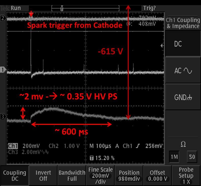
Motivation
A Time Projection Chamber (TPC) is a good choice for central tracking at EIC
• Low mass, large-continuous active volume
• Precision tracking
• Pattern recognition
• Momentum reconstruction
• Particle identification
• Requirements:
• Operate at and acquire data for collision rates as high as 500 kHz
• Continuous readout option should be considered (active gating grid is not
possible, but perhaps a passive (bi-polar) one is)
• Operate in magnetic field in the range 1.5 - 3 T
• Limited space: r ~ 80 cm, z ~ +/-100cm inside a SC solenoidal magnet.
• Main challenge: Space Charge Distortions of the E-field will be the main degradation
factor for tracking and dE/dx performance (due to high interaction rate at ultimate
EIC luminosity, possibly high backgrounds, and high demands on precision)
• Crucial EIC TPC parameters : ion back flow (IBF), energy resolution (dE/dX), electron
and ion drift speed, electron diffusion (in E- and B- fields), gain structure, and
stability
B. Azmoun CPAD2021 2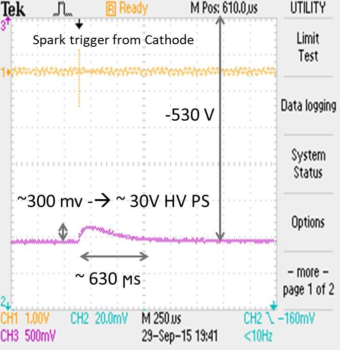
EIC TPC Gas Mixture Options
One TPC gas option that satisfies most criteria is a mixture of Ne + CF4
sPHENIX TPC selected this mixture: low diffusion (for high spatial resolution) and high ion mobility
(Ar provides greater primary ionization and may be preferable in terms of energy resolution)
Three issues:
• Strong CF4 electron absorption resonance
• Possible transfer of ion charge: Ne+ + CF4 → Ne + CF3+ + F [1]
• Both components are transparent to UV, and can be a source of scintillation causing photon feedback
Solution:
• Add a “cool” gas component with an energy of ionization less than that for CF4 [2]
• Add methane (CH4) component
• permits transfers of positive charge from the Ne+ ions to CH4+
• does not degrade diffusion, or the electron and ion drift velocities
• known to be an effective quencher to stabilize gain process
• for safety reasons the level of CH4 is generally kept at or below 10%
[1] D.J.G. Marque et al, “Experimental ion mobility measurements in Ne-CF4,” 2019 JINST 14 P04015.
[2] J. Va’vra, “Wire Chamber Gases,” SLAC-PUB-5793.
B. Azmoun CPAD2021 3
Percentage of CF4
Initial R&D question: what percentage of CF4 used in a Ne +
CH4 (10%) gas mixture?
• GARFIELD simulation results to consider [3]:
• CF4 percentages have a small impact on transverse
diffusion and electron drift speed
• Though, ion mobility increases by a factor 2 for gas
mixtures with 10% CF4 compared to 50%
• Electron absorption probability decreases with increasing
CF4 percentage (ie, better energy resolution at higher %)
• The magnitude of the electric field should be increased to
maintain the same gas gain with increasing CF4
percentages (ie, lower gain at higher %)
• Thus, the gas gain (Townsend coefficient ) and energy
resolution (electron attachment probability) are the main
trade-off [3] Prakhar Garg, private communication,
http://skipper.physics.sunysb.edu/~prakhar/tpc/HTML_Gases/split.h
tml
B. Azmoun CPAD2021 4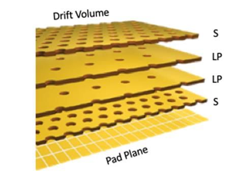
Gain Structure Options to Minimize IBF
Layered MPGD amplification stages provide a means to control the flow
of charge by tuning the electric field in several drift gaps
Mis-aligned hole pattern,
Increased hole pitch
Main IBF suppression:
Low Transfer Field
• A 4GEM ion blocking scheme was realized by the ALICE TPC
upgrade project using 4 unique GEM foils • A novel hybrid MMG + 2GEM scheme was proposed by the Yale
• The sPHENIX TPC will utilize a similar concept with some University team as an alternative to the ALICE concept
essential modifications • Fully exploits large Edrift/Einduction field ratio of MMG to strongly
• Top GEM Gain =1 (~Zero fluctuations, DE/E undamaged) suppress IBF
• Sacrifice some electron transparency at lower gain stages to • Small GEM gain (low IBF): GEMs effectively transfer primary
improve IBF charge and simultaneously act as effective IBF shield
B. Azmoun CPAD2021 5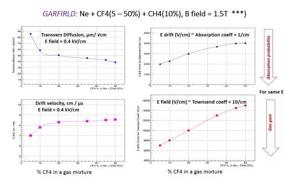
IBF Comparison w/ ALICE Gas Mixture
MMG is the primary gas gain element with a maximum field ratio
between the amplification and induction gaps, resulting in a MMG ALICE TPC Gas mixture: Ne (90) + CO2(10) + N2(5)
IBF value of ~1% or lower
• The voltage on the top GEM assures a continuous drift field in the
TPC volume and provides small effective gain to preserve electron
statistics for good energy resolution
• The extraction field (between GEMs) can be varied without
destroying other parameters (easy tuning)
E drift: 0.4 kV/cm, Gain ~ 2100
• The second GEM transfers electron clusters from the first
gain step (a high E-field) to the MMG induction gap (a very
low E-field), with effective gain for GEM2 is less than one
• Other possible parameters are different pitches and/or patterns of
the GEM holes.
All critical TPC parameters of the 4GEM setup can be
obtained for the MMG + 2 GEMs option, with even lower [6] S. Aiola et al, NIM 834 (2016) 149
IBF by a factor 2 – 2.5 and smaller max voltage
B. Azmoun CPAD2021 6
Two Gain Options for EIC TPC
MMG + 2 GEMs: Ne + CF4 + CH4 gas mixtures ALICE TPC 4GEM upgrade: Ne + CF4 + CH4 mixtures
Ne + CF4(45%) + CH4(10%)
Ne + CF4(45%) + CH4(10%)
Ne + CF4(35%) + CH4(10%)
Ne + CF4(35%) + CH4(10%)
Ne + CF4(20%) + CH4(10%)
Ne + CF4(10%) + CH4(10%)
Ne + CF4(10%) + CH4(10%)
E drift: 0.4 kV/cm, Gain ~ 2200. E drift: 0.4 kV/cm, Gain ~ 2100
For the MMG + 2GEM option 10 percent of CF4 provides the best performance in terms of energy
resolution and IBF, while for the 4GEM option ~35 - 40% performs best.
• Best IBF results for 12% E. Res: 0.40% (MMG + 2 GEMs) and 0.60% (4 GEMs)
• Best IBF results for 16% E. Res: 0.18% (MMG + 2 GEMs) and 0.40% (4 GEMs)
B. Azmoun CPAD2021 7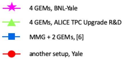
Stability Tests with x-ray Source
MMG + 2 GEMs, Ne + CF4(10%) + CH4(10%)
MMG + 2GEM exposed to high rate of x-
rays with anode current reaching 10nA/cm2 dV=450V E drift – 0.4 kV/cm, E transfer – 2.0 kV/cm,
E induction – 0.075 kV/cm
• Similar probability of MMG sparking that Gain: - ~2200, - ~4000.
could occur when high momentum dV=480V GARFIELD: E-field: 0.4 kV/cm, B-field: 1.5 T,
particles interact in the mesh material Electron drift velocity: 7.8 cm / µs, Tr.
Diffusion: 58 µm / √cm.
• Stability test performed at 2 different MMG
potentials: 450V and 480V
• Stable operation: 7 hrs of running with no
spark!
B. Azmoun CPAD2021 8Resistive Layer Protection
In the event of a spark, a resistive
protection layer on the r/o reduces the Ar+CO2(10%)
induced voltage drop and dead time
• 10x10cm2 MMG + 4x7.5mm2 pad r/o
• Spark trigger rate ~ 1/20 s
• Signal from divider connected to MMG mesh
• Signals recorded on oscilloscope
Results:
• No Protection Layer
• HV drop = 30V (significant gain drop)
• 630ms recovery time
• With Resistive Layer: 1MW/cm2
• HV drop ~0.4V (negligible effect)
• ~600ms recovery time
B. Azmoun CPAD2021 9Low Mass Readout Options for TPC
In order to measure the outgoing electron in EIC collisions with high precision momentum and tracking, a dense readout at
the TPC endcap (for |h|>1) must be avoided
Possible solutions
A. Si-based readout: TimePix with 55x55mm2 pixel (demonstrated with 3GEM or Ingrid gain options by ILC team)
Large sampling of primary ionization electrons with excellent dE/dx performance
Data flow/volume can potentially be challenging, but for EIC events with relatively few tracks per event, this may not be an
issue
B. Couple charge from large (~1x10mm2) anode pads of TPC r/o plane to input of high density channels of Si readout
Additional CCD element may be needed to facilitate the transfer of charge
C. Reposition TPC endcap readout in the electron-going direction to dramatically minimize material thickness for |h|>1
Split TPC into two halves: one half with cathode near IP, one standard
Challenges
Central Field Cage Cathode Dual Cathodes • This concept needs to be
tested with simulation
MPGD R/O + Services • Rapidity hole near h=0
• Impact on Physics seems small
(Jets, Abs. X-section
measurements?)
• Acceptance of vertex det.
obscured
• Routing of services, cabling
B. Azmoun CPAD2021 10Summary
Investigated crucial parameters for a future high rate TPC at the EIC: ion back flow, energy resolution
(dE/dx), electron and ion drift speed, electron diffusion, and stability
Concentrated on two MPGD gain structures: 4GEM and MMG+2GEM
For the hybrid option, we achieved an IBF below 0.3% and an DE/E < 12% for Fe55 x-rays at a gain of ~2000 for several
gas mixtures
Optimal gas mixture ratios were identified for both the 4GEM and hybrid option
We have demonstrated the stability of operation for the hybrid gain element with the optimal working gas
We have also showed that for relatively rare spark events, the impact on the performance of the hybrid gain element
is negligible
Conclusion: The hybrid amplification stage allows for a TPC design that can operate in a continuous mode, serves as a
viable option to limit space charge distortions in high-rate TPCs, and guarantees that dE/dx, ionization cluster space
reconstruction resolution, drift parameters and detector stability will not be compromised
B. Azmoun CPAD2021 11You can also read