PET Imaging of the Brain for Technologists - CTN Webinar Series 2016 - (IDEAS) Study
←
→
Page content transcription
If your browser does not render page correctly, please read the page content below
PET Imaging of the Brain for
Technologists

CTN Webinar Series 2016

Disclosures
Financial Disclosure
Speakers: LisaAnn Trembath & Adam Opanowski
  • LisaAnn Trembath is an employee of Avid Radiopharmaceuticals, Inc., a
    wholly-owned subsidiary of Eli Lilly and Company.
  • Adam Opanowski is an employee of the American College of Radiology

Program Director: John H. Hoffman, MD
       • Contradyn, Inc – Consultant/Advisor, Investment Interest
       • GE Healthcare – Consultant/Advisor, Scientific Study/Trial
Bonnie Clarke (SNMMI):             Nothing to Disclose
Jina Kim (SNMMI):                  Nothing to Disclose

FDA Disclosure
This presentation will not include discussion of any device or drug requiring
FDA approval.

                                                                                2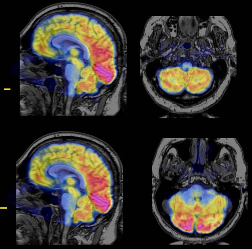
Learning Objectives
Upon completion of this presentation, participants
will be able to:
• Recognize key anatomical structures on FDG
  PET and CT images
• Identify the lobes of the brain and their major
  functions
• Describe key parameters used to obtain high
  quality FDG PET/CT images
• Discuss the role of PET imaging in patients with
  brain abnormalities
                                                     3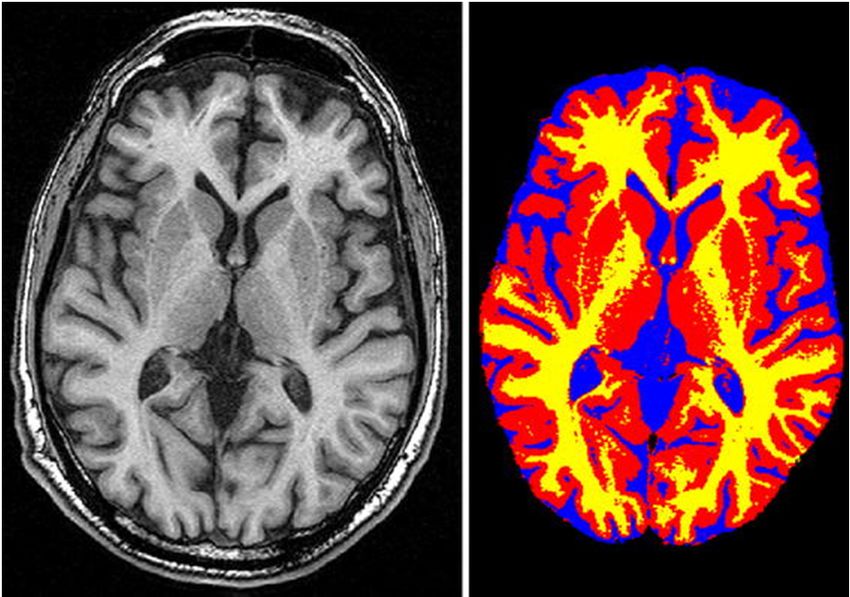
PET Brain Anatomy Review

                           4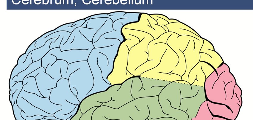
Cortex
   Convoluted walls of nervous tissue (gray matter) folded
   within the cranial vault; convolutions increase surface area
   for more neurons
      • Cerebral cortex divided into four lobes.
      • Cerebellar cortex divided into right and left hemispheres.

                        Cerebral cortex                        Cerebellar hemispheres
Images courtesy of “The Whole Brain Atlas”, Johnson & Becker                            5
http://www.med.harvard.edu/aanlib/home.htm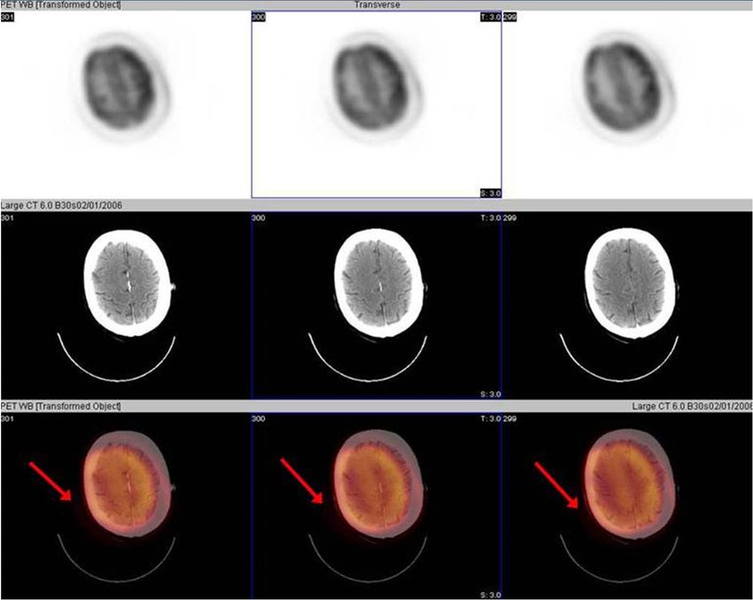
Gyrus, Sulcus, Fissure

                                                       Superior-frontal               Sylvian fissure:
                                                      gyrus: associated             boundary between
                                                     with self-awareness           frontal and temporal
                                                                                           lobes

   • Gyrus: convoluted ridge between anatomical grooves
   • Sulcus: depression or furrow
   • Fissure: large sulcus that divides sections of the brain
Images courtesy of “The Whole Brain Atlas”, Johnson & Becker; http://www.med.harvard.edu/aanlib/home.htm   6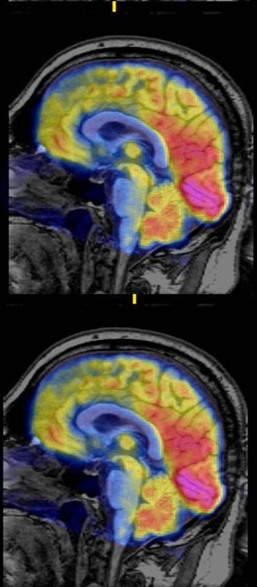
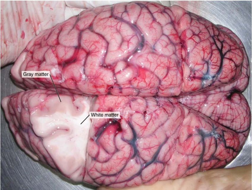
Gray and White Matter
                                                                                    Gray

                                                                                    White

                                                                                    CSF

     www.wickipedia.com                        Ikram, et al. Eur J Epidemiol 2011

Gray matter: 40% of brain volume; uses 94% of total oxygen that goes to the brain;
contains most of the brains cell bodies; responsible for generating and processing
signals; associated with processing information and cognition
White matter: 60% of brain volume; composed of nerve fibers (axons) surrounded
by fatty myelin sheath; responsible for transmitting signals; relays and coordinates
information between parts of cerebrum; from cerebrum to cerebellum & brain stem.
                                                                                          7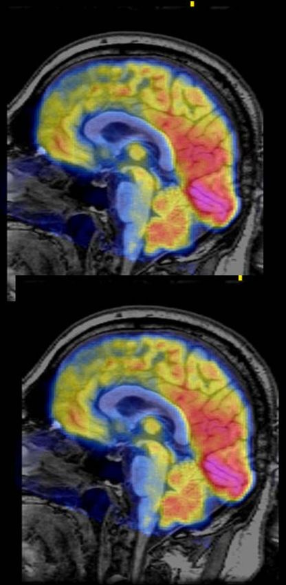
Cerebrum, Cerebellum

                                                      Parietal
                                                                                        *FDG PET fused

                             Cerebrum
                                                                                        with T1 MR image
         Frontal

                                                                                  Occipital
                                 Temporal

                                                                    Cerebellum
Image courtesy of “The Whole Brain Atlas”‐Johnson & Becker. http://www.med.harvard.edu/aanlib/home   8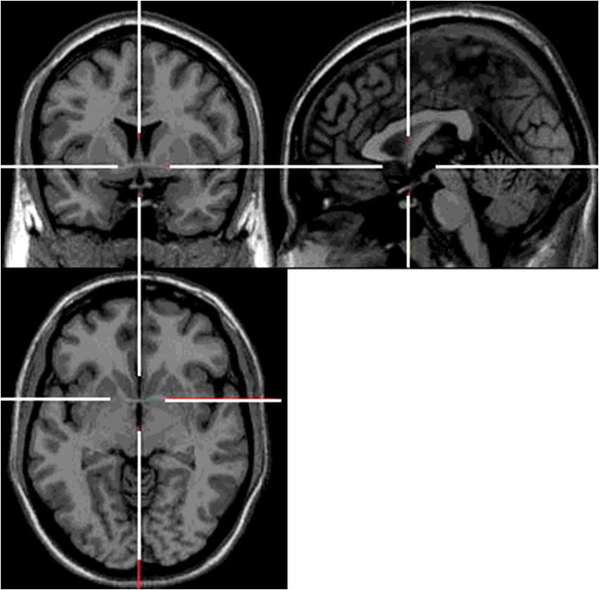
Transaxial Anatomy
                                                                                                     Frontal

                                        Cerebellum
                                                                                                         Parietal

                                                                                                          Frontal

                                      Occipital                                                         Parietal

                                    Frontal
                                                                                                         Frontal
                                            Temporal

                                          Parietal

Image courtesy of “The Whole Brain Atlas”‐Johnson & Becker. http://www.med.harvard.edu/aanlib/home
                                                                                                           9
Coronal Anatomy
                                      Frontal                                                            Frontal/
                                                                                                         Parietal
                                                                                                        Temporal

                                                                                                 Cerebellum

                                       Frontal

                                          Temporal                                                       Parietal
                                                                                                        Occipital
                                                                                                     Cerebellum

                                         Frontal
                                                                                                       Parietal
                                          Temporal
                                                                                                       Occipital
                                         Cerebellum

Image courtesy of “The Whole Brain Atlas”‐Johnson & Becker. http://www.med.harvard.edu/aanlib/home        10
Sagittal Anatomy
Frontal
Frontal Parietal
Temporal
Occipital
Occipital
Cerebellum
Frontal
Parietal
Frontal Parietal
Occipital Occipital
Cerebellum
Cerebellum
Image courtesy of “The Whole Brain Atlas”‐Johnson & Becker. http://www.med.harvard.edu/aanlib/home 11PET Brain Imaging Technique
12The Brain and Glucose
• Glucose is used as a major energy
source for the brain
• Since the brain does not have
substantial glucose storage capacity, it
requires a continuous supply of
glucose from plasma to maintain its
functions
• If neurons in a certain part of the brain
are not functioning normally, the
change can be reflected by the
amount of glucose utilization FDG uptake in grey matter 1‐2
hours post‐injection
Images courtesy of: www.med‐ed.virginia.eduFDG – Mechanism of Action
• FDG competes with glucose for transport into the
cell and for enzymatic phosphorylation by
hexokinase
• Once FDG is phosphorylated into FDG-6-
phosphate it is trapped inside the cell and does
not undergo further metabolism
• It cannot be further degraded via the glycolysis
pathway nor can it undergo dephosphorylation
Image courtesy of content.onlinejacc.org
J Am Coll Cardiol. 2010;55(23):2527‐2535.
doi:10.1016/j.jacc.2009.12.061FDG – Blood Sugar Levels
• High blood sugar levels can decrease FDG
uptake by competitive inhibition because both
glucose and FDG use the same transporters
• It is recommended that patients fast for a
minimum of 4 hours before the FDG injection
• If the blood sugar level is greater than 150 – 200
mg/dL prior to injection, the scan should be
rescheduled
Society of Nuclear Medicine Procedure Guideline for FDG PET Brain Imaging v1.0FDG – Blood Sugar Levels
• Diabetic patients should be scanned early in the
morning before the first meal
• Doses of insulin and hypoglycemic medication
should be titrated the night before and morning
of the study
• Before scheduling an FDG-PET study, diabetic
patients should test their ability to maintain
reasonable glucose levels after fasting
Society of Nuclear Medicine Procedure Guideline for FDG PET Brain Imaging v1.0Uptake Time
• The environment should be stable for at least 30
minutes prior to FDG injection and subsequent
uptake phase (at least 30 min.)
• Patient should be placed in a quiet, dimly-lit
room and minimize interaction prior to, during
and at least 30 min. post injection
• Instruct patient to relax, not to speak or read and
to avoid major movements during uptake phase
Society of Nuclear Medicine Procedure Guideline for FDG PET Brain Imaging v1.0Patient Positioning • Prior to starting the scan, have the patient remove glasses, earrings, hair clips/combs, and hearing aids (if possible) • Place patient's head in ‘holder’ using foam or folded sheets so that canthomeatal plane line is vertical (imaginary line from lateral corner of eye to the ear canal) • Small deflections of the canthomeatal line from the vertical position can signify abnormal head tilt • While standing at the head of the scanning table correct for any signs of head rotation
Patient Positioning, cont.
• Strap the patient’s head using self-adherent wrap
  (cohesive tape)
• Position the patient’s arms at their sides and
  stabilize them (in accordance with local practice);
  may include bed straps or other measures to
  minimize patient movement during the scan
• Place a foam wedge or pillow under the knees
  and use blankets for comfort
• Use laser system to properly position the head
• Position brain in center of the FOV, including
  complete coverage of cerebellum
Correct Head Positioning

Vertex of
                                                                 Chin should rest
 should reach
                                                                    in neutral
head holder’s
                                                                     position
superior edge

                                  Cantho‐meatal line should be
                                       oriented vertically

J. Nucl. Med. Technol. 2013;41:105‐107                                              20
Incorrect Head Positioning
Incorrect
positioning
of head Chin is deflected
within toward neck
holder
Canthomeatal line
should be oriented
vertically
J. Nucl. Med. Technol. 2013;41:105‐107 21Motion
Artifacts in
attenuation
correction
Potential
inaccuracy in
recording
location of tracer
deposition
Study should be
repeated with
pre‐exam
coaching
www.med‐ed.virginia.eduStatic Acquisition
Depending on the clinical question and type of
equipment available, imaging may include:
• Static (limited field tomographic images)
– Static protocols offer clinical applicability and the
relative tracer uptake is of interest
– Relative tracer uptake is characterized as the
Standardized Uptake Value (SUV) and details of
the errors with static SUV have been well
documented
– May impose a bias by arbitrarily choosing a
single time frame to represent overall tracer
metabolism
Society of Nuclear Medicine Procedure Guideline for FDG PET Brain Imaging v1.0Dynamic Acquisition
Dynamic (multiple sequential images in a single
FOV)
• May be used when absolute quantification of
regional metabolic rates of glucose are needed
• Studies consist of a sequence of serial images in a
limited FOV (1 bed position), starting at the time of
tracer administration and continuing for 60-90
minutes
• Not commonly used for clinical routine
• Requires blood samples to be obtained during
imaging (venous or arterial)
Society of Nuclear Medicine Procedure Guideline for FDG PET Brain Imaging v1.0Image Acquisition
Depending on the clinical question and type of equipment
available, imaging may include:
Static Dynamic
Static protocols offer clinical applicability May be used when absolute quantification
and the relative tracer uptake is of of regional metabolic rates of glucose are
interest needed
Relative tracer uptake is characterized as Studies consist of a sequence of serial
the Standardized Uptake Value (SUV) and images in a limited FOV (1 bed position),
details of the errors with static SUV have starting at the time of tracer administration
been well documented and continuing for 60‐90 minutes
May impose a bias by arbitrarily choosing Requires blood samples to be obtained
a single time frame to represent overall during imaging (venous or arterial)
tracer metabolism
Society of Nuclear Medicine Procedure Guideline for FDG PET Brain Imaging v1.0 25PET Brain Imaging
Acquisition Mode
• 2D – Coincidence detection only between
adjacent detector rings
– Lead or tungsten plates (septa) between each ring of
individual crystals
• 3D – Coincidence detection using all detector
rings
– No septa between rings
J. Nucl. Med. Technol. March 1, 2001 vol. 29 no. 1 4‐11, Timothy Turkington.2D vs. 3D Emission Scans
• Most systems today use 3D acquisition
– If 2D acquisition is used, longer acquisition times are
required to achieve adequate count density
2D Emission Scan Fully‐3D Emission Scan
Lower sensitivity (longer acquisition Higher sensitivity (shorter acquisition
time) time)
Less data storage More data storage
Simpler to reconstruct Harder to reconstruct
FOV for random coincidences is FOV for random coincidences is
smaller larger
Society of Nuclear Medicine Procedure Guideline for FDG PET Brain Imaging v1.0 27Image Processing • FBP, commonly used filters are Hanning and Shepp-Logan • Iterative reconstruction is increasingly being employed • Refer to camera manufacturer’s recommendations for best choices of iterations, subsets, and smoothness • Reconstructions may be tracer-specific Society of Nuclear Medicine Procedure Guideline for FDG PET Brain Imaging v1.0
Image Processing
    • Images are reconstructed in the form of
      transaxial 128 x 128 or 256 x 256 matrix size
    • Typical pixel size is 2-4 mm
    • Depending on the resolution of the PET system,
      a final image resolution may vary between 2.5-
      10 mm FWHM
          – This typically yields adequate image resolution and
            signal-to-noise ratios

Society of Nuclear Medicine Procedure Guideline for FDG PET Brain Imaging v1.0
Data Display
• A standardized image display is advocated to
ensure an appropriate, symmetrical and most
readily interpretable representation of the
reconstructed dataset
• Internal landmarks can be used for reorientation
• Reorientation procedures based on
intercommissural line are commonly used
Society of Nuclear Medicine Procedure Guideline for FDG PET Brain Imaging v1.0Intercommissural line (ICL)
The intercommissural line (ICL) passes
through the center of the anterior and
posterior commissure
The AC‐PC line goes from the
superior surface of the anterior
commissure to the center of the
posterior commissure
31
Tutorial for MRIcro. www.mccauslandcenter.sc.eduData Display
The display of additional coronal and sagittal
images is required
• 3D display optional
– Volume surface renderings may be subject to artifacts
– should be used in combination with standard slice
displays
• Reorientation parallel to the temporal lobe in the
evaluation of epilepsyFDG Pitfalls, Artifacts, Sources of Error
Medications altering cerebral metabolism include:
• Sedatives
• Drugs such as amphetamines, cocaine
• Narcotics
• Anti-psychotic medications
• Corticosteriods
Society of Nuclear Medicine Procedure Guideline for FDG PET Brain Imaging v1.0FDG Pitfalls, Artifacts, Sources of Error • Most medications predominately alter global metabolism with modest effects on regional distribution • Hyperglycemia • Patient motion during the data acquisition may result in image artifacts and render the study non-interpretable • Mis-registration between the emission and transmission scans Society of Nuclear Medicine Procedure Guideline for FDG PET Brain Imaging v1.0
PET Amyloid Imaging of the Brain

                                   35
Amyloid Imaging
• PET with amyloid imaging agents has the ability
to determine in vivo plaque density
– Beta-amyloid neuritic plaque density is a hallmark of
Alzheimer’s disease (AD)
• Presently there are no disease-modifying
treatments for AD
– Confirmation or exclusion of AD provides an
opportunity for clinical trial eligibility and
family/caregiver planning
36β-amyloid • The brains of people with AD have an abundance of abnormal structures • Amyloid plaques are found in the spaces between the brain’s nerves cells • Plaques consist largely of insoluble deposits of an apparently toxic protein peptide (beta- amyloid)
Amyloid – Mechanism of Action
• Amyloid imaging agents bind to β-amyloid (AB)
  plaques in the cortical gray matter
• The amyloid imaging tracer binds to the β-
  amyloid plaques and the radioisotope produces
  a positron signal to be detected by the PET
  scanner

   No evidence of                    High levels of
   amyloid plaques                   amyloid plaques

Images from www.amyvid.com
Amyloid Imaging
                      • The first PET tracer specific
                        for β-amyloid plaques was
                        labeled with 11C (Pittsburgh
                        compound B)
                      • The FDA has approved
                        three 18F-labeled amyloid
                        tracers
                             –   18F-Florbetapir(Amyvid™)
                             –   18F-Flutemetamol (Vizamyl™)

                             –   18F-Florbetaben (NeuraCeq™)

                  J Nucl Med 2011; 52:1733‐1740
Healthy   AD
Amyloid Imaging Patient Preparation
Patient preparation for amyloid imaging
• Fasting not required
• No discontinuation of medications
• Glucose monitoring not required
• Environment post injection (e.g., no need for
dark room or limitation of stimulus)
• Encourage fluids for hydration and clearance
SNMMI Procedure Standard‐EANM Practice Guideline for Amyloid PET Imaging of the Brain, 2016; Available at www.snmmmi.orgProduct Specific Administration and Dosing
Injection
Dose Injection Flush Patient instructions
Supplies
Catheter less than
10mCi (370MBq)
Florbetapir 1.5 inches; use Single Bolus
10mL or less
HDPE syringe4
Hydrate and encourage
5 mCi (185 MBq) 10-15mL
Flutemetamol Bolus IV within voiding before and after
10mL or less saline
40 seconds injection5
Avoid close contact with
8.1 mCi (300 MBq) Slow bolus IV 10mL young children and
Florbetaben
0.5-10mL (6 sec/mL) saline pregnant women for 24
hours post injection7Imaging Workflow
Amyloid Standard Acquisition
Patient Positioning
Imaging Agent Uptake Time Scan Time
Florbetapir 30-50 minutes 10 minutes The patient should be supine and head positioned to
post injection center the brain, including the cerebellum, in the PET
scanner field of view. Reducing head movement with
tape or other flexible restraints may be employed.4
Flutemetamol 90 minutes 20 minutes Position the patient supine with the brain (including
post injection the cerebellum) within a single field of view. The
patients head should be tilted so that the anterior
commissure-posterior commissure plane is at a right
angle to the bore-axis of the PET scanner, with head
positioned in a suitable head support. Reducing head
movement with tape or other flexible restraints may be
employed.5
Florbetaben 45-130 minutes post 15-20 minutes Patient should be supine with the head positioned to
injection the center of the brain, including the cerebellum, in
the PET scanner field of view. Reducing head
movement with tape or other flexible head restraints
may be employed.7
See slide 48 for references.Amyloid Imaging Display
This discussion of display techniques for PET brain
amyloid agents is not a substitute for manufacturer
specific reader training.
For details on image display and interpretation for each
amyloid tracer, refer to the product labels.
43Amyvid (florbetapir)
• Eli Lilly and Company has
Negative
developed online
resources for physicians
and technologists
– Recommended dosing and
administration instructions
Positive – Image acquisition
– Image display
– Image interpretation (reader
training)
www.amyvidhcp.comAmyvid (florbetapir)
Normal preserved gray‐white
contrast with cortical
radioactivity less than the
adjacent white matter
Decreased gray‐white
contrast with increased
cortical radioactivity that is
comparable to the
radioactivity in the adjacent
white matter
Florbetapir Package InsertAmyvid (florbetapir)
White matter tracks can
be delineated from the
frontal lobe to parietal
lobe
Scalloped appearance is seen Low levels of tracer in scalp
with “fingers” of white matter or skull that should be
in the frontal cortex distinguished from gray
matter uptake by its shape
and position
White matter tracts are
clearly identified throughout
the occipital/temporal area
Florbetapir Package InsertAmyvid (florbetapir)
White matter tracks are
difficult to fully identify as
they travel from frontal to
parietal lobe
Low levels of tracer in scalp or
Gray matter in medial skull that should be
parietal cortex (precuneus) distinguished from gray matter
has increased uptake uptake by its shape and
position
Borders of white matter
tracts in occipital/temporal
area are lost in places
Florbetapir Package InsertVizamyl (flutemetamol)
• GE Healthcare
developed and
launched an electronic
reader program
• The program instructs
physicians in the
appropriate method to
interpret Vizamyl
images
• Can be accessed by
healthcare
Flutemetamol Package Insert
professionals onlineVizamyl (flutemetamol)
Less uptake in More radioactivity
striatal regions in the striatal
regions
White matter Absence of white
sulcal pattern matter sulcal
with a color pattern with
intensity that intensity radiating to
tapers to the a sharply defined
periphery convex edge
In both the frontal and lateral temporal regions, the intensity is
higher in the gray matter regions wheb comparing the Positive
and Negative scans
Flutemetamol Package InsertVizamyl (flutemetamol)
The posterior cingulate (pc)
region which is superior and
posterior to the corpus callosum ‐
the intensity is below 50% of peak
White matter sulcal pattern in
inferior parietal (ip) regions that is
not evident on the positive image
The posterior cingulate (pc)
region which is superior and
posterior to the corpus callosum ‐
the intensity is below 50% of peak
Increased intensity in the
posterior cingulate (pc) and
increased radial extent of high
intensity to the lateral surfaces of
the parietal lobes
Flutemetamol Package Insert 50Neuraceq (florbetaben) • Electronic Media- or In-person training is provided by manufacturer • Images should be interpreted only by readers who successfully complete training • Online resources provided for healthcare professionals Florbetaben Package Insert. www.piramal.com 51
Neuraceq (florbetaben)

     Cerebellum:        Lateral temporal lobes:        Frontal lobes:             Posterior                Parietal lobes:
Contrast between       The negative scan shows       The negative scan      cingulate/precun         In the negative scan, the
                                                                                                 midline between the parietal
 the white matter            spiculated or           shows spiculated       eusAdjacent and
                                                                                                 lobes can be easily identified
(arrows) and gray           “mountainous”           appearance of white      posterior to the      (long arrow); white matter
 matter is seen in       appearance of white          matter (arrows).            splenium        has a spiculated appearance
both negative and          matter (arrows).                                  (arrow), regions    (short arrow) with low signal
   positive scans.                                    The positive scan      appear as hypo‐        near the outer rim of the
    Extracerebral                                     shows the tracer        intense “hole”             brain (dashed line)
                      The positive scan shows a
  tracer uptake in       “plumped” smooth              uptake in these         (circle) in the      In the positive scan, the
  scalp and in the                                  regions as “plumped”       negative scan     midline between the parietal
                       appearance of the outer
                                                                                                  lobes is much thinner. The
 posterior sagittal      border of the brain        smooth appearancea          The hole is
                                                                                                 cortical areas are “filled‐up”
sinus (arrowhead)     parenchyma (dashed line)      due to increased gray        “filled‐up”           and are smooth in
    can be seen.      due to tracer uptake in the   matter signal (dashed      (circle) in the   appearance as tracer uptake
                             gray matter.                    line).            positive scan.     extends to the outer52 rim of
                                                                                                            the brain
FDG and Amyloid PET
Similarities Differences
Positioning (anatomically) Uptake time
Secure head in scanner
Consistency for all follow‐up exams
Artifacts (motion, head tilt) Pre‐ and Post‐injection procedures
(glucose, environment)
NPO not required for amyloid imaging
F‐18: 110 min half‐life (FDA‐ C‐11: 20 min half‐life
approved tracers). Decay correction
Decay correction
Quality Control (scanner, clock Image interpretation (color scale,
synchronization) training)
53Amyloid PET: Pitfalls, artifacts, sources of error
• Patient motion during the data acquisition may
result in image artifacts and render the study
non-interpretable
• Mis-registration between the emission and
transmission scans
• Incorrect tracer-specific uptake time
• Positioning
54Additional IDEAS Resources
• SNMMI Webinar: Reimbursement for IDEAS
– Tuesday, 24May2016, 3:00pm EST; Denise Merlino
• CTN Webinar: Review of Amyloid Imaging and How to Register for the
IDEAS Study
– Thursday, 23June2016, 3:00pm EST; LisaAnn Trembath
– SNMMI Member Fee: $49 | Nonmember Fee: $79
• Manufacturer-provided technical support
• SNMMI Procedure Standard-EANM Practice Guideline for Amyloid PET
Imaging of the Brain; available online at www.snmmi.org
• Appropriate Use Criteria for Amyloid PET; available online at
www.snmmi.org
61Thank You !
62You can also read