Reference Architecture for Active System 800 with VMware vSphere - Dell
←
→
Page content transcription
If your browser does not render page correctly, please read the page content below
Reference Architecture for Active
System 800 with VMware vSphere
Release 1.1 for Dell PowerEdge 12th Generation Blade Servers, Dell
Networking Switches, Dell EqualLogic iSCSI SAN, and Dell Active System
Manager

Dell Virtualization Solutions Engineering

Revision: A00
Reference Architecture for Active System 800 with VMware vSphere

This document is for informational purposes only and may contain typographical errors and
technical inaccuracies. The content is provided as is, without express or implied warranties of any
kind.

© 2013 Dell Inc. All rights reserved. Dell and its affiliates cannot be responsible for errors or omissions
in typography or photography. Dell, the Dell logo, OpenManage, Force10, Kace, EqualLogic,
PowerVault, PowerConnect, and PowerEdge are trademarks of Dell Inc. Intel and Xeon are registered
trademarks of Intel Corporation in the U.S. and other countries. Microsoft, Windows, Hyper-V, and
Windows Server are either trademarks or registered trademarks of Microsoft Corporation in the United
States and/or other countries. VMware, vSphere, ESXi, vMotion, vCloud, and vCenter are registered
trademarks or trademarks of VMware, Inc. in the United States and/or other jurisdictions. Linux is the
registered trademark of Linus Torvalds in the U. S. and other countries. Other trademarks and trade
names may be used in this document to refer to either the entities claiming the marks and names or
their products. Dell disclaims proprietary interest in the marks and names of others.

July 2013 | Rev A00

                                                                                                     Page ii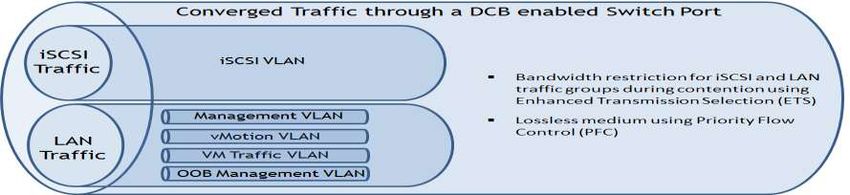
Reference Architecture for Active System 800 with VMware vSphere

Revision History
        Revision                            Description                               Date
     A00             Initial Version with Active Infrastructure 1.1 and Active   July 2013
                     System Manager 7.1 updates

                                                                                             Page iii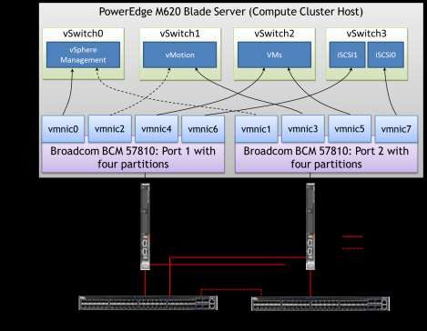
Reference Architecture for Active System 800 with VMware vSphere

Table of Contents
1     Introduction .......................................................................................................... 3
2     Audience .............................................................................................................. 3
3     Solution Overview ................................................................................................... 4
4     Design Principles .................................................................................................. 11
5     Prerequisites and Datacenter Planning ........................................................................ 12
6     Architecture ........................................................................................................ 13
    6.1    Dell Blade Network Architecture ......................................................................... 14
    6.2    Converged Network Architecture ........................................................................ 15
    6.3    Converged Network Connectivity ........................................................................ 15
    6.4    Converged Network Configuration ....................................................................... 17
7     Management Infrastructure ..................................................................................... 24
    7.1    Dell Active System Manager ............................................................................... 25
    7.2    Dell OpenManage Essentials (OME) ....................................................................... 25
    7.3    Dell Repository Manager (DRM) ........................................................................... 26
    7.4    Dell Management Plug-in for VMware vCenter (DMPVV) ............................................. 26
    7.5    Dell EqualLogic Virtual Storage Manager (VSM) for VMware ......................................... 28
    7.6    Dell EqualLogic SAN HQ .................................................................................... 28
    7.7    VMware vCloud Connector ................................................................................. 29
    7.8    Out-Of-Band Management Connectivity ................................................................. 29
8     Connecting Active System 800 to Datacenter Network ..................................................... 30
    8.1    Connecting the Dell Networking S55 switch OOB to Datacenter Network ........................ 30
    8.2    Connecting to a Dell Networking Datacenter Network ............................................... 31
    8.3    Connecting to a Cisco Nexus Data Center Network ................................................... 31
9     Scalability .......................................................................................................... 32
10    Delivery Model ..................................................................................................... 32
11    References ......................................................................................................... 34
    11.1   Dell Active Infrastructure reference: .................................................................... 34
    11.2   VMware references: ........................................................................................ 34
    11.3   Dell PowerEdge References: .............................................................................. 34
    11.4   Dell EqualLogic references: ............................................................................... 34
    11.5   Dell Management reference: .............................................................................. 35

                                                                                                                       Page 1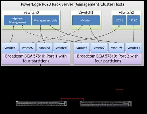
Reference Architecture for Active System 800 with VMware vSphere
Figures
Figure 1: Active System 800v Overview ............................................................................... 4
Figure 2: Active System 800v Network Topology (Logical View) with optional 2 nd Chassis ................. 13
Figure 3: I/O Connectivity for PowerEdge M620 Blade Server................................................... 14
Figure 4: Converged Network Logical Connectivity ............................................................... 17
Figure 5: Conceptual View of Converged Traffic Using DCB ..................................................... 18
Figure 6: vSwitch and NPAR Configuration for the Hypervisor Hosts ........................................... 21
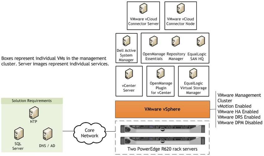
Figure 7: Management Components .................................................................................. 25
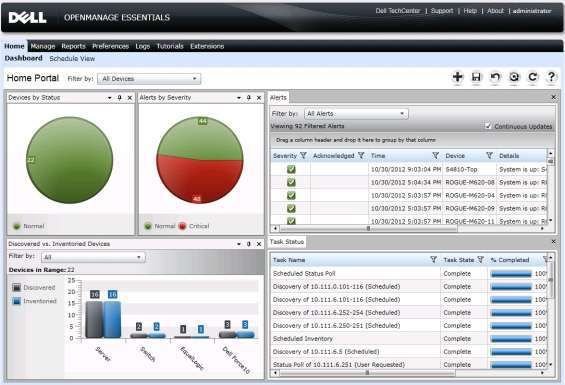
Figure 8 OME Dashboard................................................................................................ 26
Figure 9: Connectivity of OOB management components ........................................................ 29
Figure 10: S55 Connectivity to Datacenter OOB Network (Default Option) ................................... 30
Figure 11: Alternative OOB Connectivity - Dell Networking S55 Switch to Dell Networking S4810
Switches ............................................................................................................. 30
Figure 12: Active System 800 connectivity to Dell Networking Z9000 Switch ................................ 31
Figure 13: Active System 800 connectivity to Cisco Nexus 5548 ................................................ 31
Figure 14: Active System 800v Single Chassis: Rack Overview .................................................. 32
Figure 15: Active System 800v Two Chassis and Maximum Storage: Rack Overview ........................ 33
Tables
Table 1: Solution Components .......................................................................................... 5
Table 2: VLAN Overview ................................................................................................ 19
Page 2
Reference Architecture for Active System 800 with VMware vSphere

1 Introduction
Dell™ Active Infrastructure is a family of converged infrastructure solutions that combine servers,
storage, networking, and infrastructure management into an integrated and optimized system that
provides general purpose virtualized resource pools. Active Infrastructure leverages Dell innovations
including unified management (Active System Manager), converged LAN/SAN fabrics, and modular
server architecture for the ultimate converged infrastructure solution. Active Infrastructure helps IT
rapidly respond to dynamic business demands, maximize data center efficiency, and strengthen IT
service quality.

The Active System 800 solution, a member of Dell Active Infrastructure family, is a converged
infrastructure solution that has been designed and validated by Dell Engineering. It is available to be
racked, cabled, and delivered to your site to speed deployment. Dell Services will deploy and configure
the solution tailored for business needs, so that the solution is ready to be integrated into your
datacenter. Active System 800 is offered in configurations with either VMware® vSphere® (Active
System 800v) or Microsoft® Windows Server® 2012 with Hyper-V® role enabled (Active System 800m)
hypervisors. This paper defines the Reference Architecture for the VMware vSphere based Active
System 800v solution.

Active System 800v offers converged LAN and SAN fabric design to enable a converged infrastructure
solution. The end-to-end converged network architecture in Active System 800v is based upon Data
Center Bridging (DCB) technologies that enable convergence of all LAN and iSCSI SAN traffic into a
single fabric. The converged fabric design of Active System 800v reduces complexity and cost while
bringing greater flexibility to the infrastructure solution.

Active System 800v includes Dell PowerEdgeTM M1000e blade chassis with Dell PowerEdgeTM M I/O
Aggregator, Dell PowerEdgeTM M620 blades, Dell EqualLogic™ Storage, Dell Networking switches, and
VMware vSphere 5.1. The solution also includes Dell PowerEdgeTM R620 servers as management servers.
Dell Active System Manager, VMware vCenter Server, EqualLogic Virtual Storage Manager for VMware,
and Dell OpenManage™ Essentials are included with the solution.

2 Audience
This document provides an overview of the Active System 800 solution. Readers, including CTOs and IT
managers, can use this document to understand the overview and scope of the solution. IT
administrators and managers can use this document to understand the solution architecture.

                                                                                                  Page 3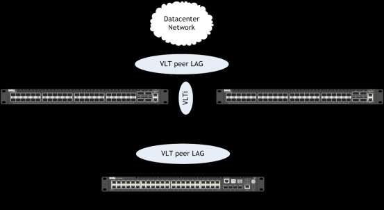
Reference Architecture for Active System 800 with VMware vSphere

3 Solution Overview
This section provides a high-level product overview of the major components of the Active System 800
as illustrated in Figure 1 . Readers can skip the sections of products with which they are familiar.

                                Figure 1: Active System 800v Overview

                                        VMware vSphere 5.1 Hypervisor
                                        ·       vMotion, Storage vMotion
                                        ·       VMware HA and DRS

                                        Management Components
                                        ·   Dell Active System Manager
                                        ·   VMware vCenter Server
                                        ·   Dell Management plug-in for VMware vCenter
                                        ·   Dell OpenManage Essentials
                                        ·   Dell EqualLogic Virtual Storage Manager (VSM) for VMware
                                        ·   Dell EqualLogic SAN HeadQuarters (HQ)
                                        ·   Dell Repository Manager
                                        Cloud Enablement
                                            ·   VMware vCloud Connector for Dell vCloud connectivity

                                        Compute Cluster - Dell PowerEdge Blade Servers
                                        · Energy efficient Dell PowerEdge M1000e enclosure
                                        · Up to 32 Dell PowerEdge M620 blade servers
                                        · CPU: 2x Intel® Xeon® 2.2GHz 95W 8C
                                        · Memory: 128 GB (16x8GB) 1333 MHz RDIMMs
                                        · NDC: BCM 57810-k (2x10GbE 10GBASE-KR)
                                        · PowerEdge M I/O Aggregator or Dell Networking MXL
                                          10/40GbE blade switch
                                        · IDRAC7 Enterprise
                                        Management Cluster – Dell PowerEdge R620
                                        · CPU: 2x Intel® Xeon 2.2GHz 95W 8C
                                        · Memory: 128 GB (16x8GB) 1333 MHz RDIMMs
                                        · NDC:     BCM 5720 (4x 1GbE RJ-45)
                                        · NIC:     BCM 57810 PCI-e (2x 10GbE SFP+)
                                        · iDRAC: iDRAC7 Enterprise

                                        Dell Networking S4810 48x 10GbE + 4x 40GbE Ports
                                        · 2x S4810 High-density 48 port 10GbE switches for
                                           converged LAN and SAN traffic
                                        · 80GbE ISL between the switches

                                        Dell Networking S55 44x 1GbE + 4x SFP Ports
                                        · 10/100/1000MbE Out of Band (OOB) Mgmt Traffic

                                        Dell EqualLogic PS6110 Series iSCSI Storage
                                        · 10GbE Controllers with up to 8 Arrays
                                        · Default Solution
                                              1x PS6100X per 4x hosts
                                                    with (24) 2.5" 900GB 10k

                                                                                                       Page 4
Reference Architecture for Active System 800 with VMware vSphere
Table 1 below describes the key solution components and the roles served.
Table 1: Solution Components
Component Description Role
Compute Cluster Dell PowerEdge M620 blade Host highly-available virtual
servers running embedded machines (VMs)
VMware vSphere 5.1
Management Cluster Two Dell PowerEdge R620 Host management VMs: Dell
servers with embedded VMware Active system Manager, VMware
vSphere 5.1 hosting management vCenter Server, Dell
VMs. Management Plug-in for VMware
vCenter, Dell OpenManage
Essentials, Dell EqualLogic
Virtual Storage Manager (VSM)
for VMware, Dell EqualLogic SAN
HeadQuarters (SAN HQ), VMware
vCloud Connector, Dell
Repository Manager
Storage Dell EqualLogic PS6110 Series Provide shared storage for the
controllers with 24 bay 2.5” SAS ESXi Hypervisor clusters
enclosures or 24 Bay 3.5” SAS
enclosures
Converged Network Switches Two Dell Networking S4810 and Support VM, vMotion,
two Dell Converged I/O modules Management, and iSCSI traffic
for the blade chassis (PowerEdge
M I/O aggregator or Dell
Networking MXL)
Out-of-Band (OOB) Management One Dell Networking S55 Provide OOB management
Switch connectivity
VMware vSphere 5.1: VMware vSphere 5.1 includes the ESXi™ hypervisor as well as vCenter™ Server
which is used to configure and manage VMware hosts. Key capabilities for the Enterprise Plus license
level include:
· VMware vMotion™: VMware vMotion technology provides real-time migration of running virtual
machines (VM) from one host to another with no disruption or downtime.
· VMware High Availability (HA): VMware HA provides high availability at the virtual machine
(VM) level. Upon host failure, VMware HA automatically re-starts VMs on other physical hosts
running ESXi. VMware vSphere 5.1 uses Fault Domain Manager (FDM) for High Availability.
· VMware Distributed Resource Scheduler (DRS) and VMware Distributed Power Management
(DPM): VMware DRS technology enables vMotion to automatically achieve load balancing
according to resource requirements. When VMs in a DRS cluster need fewer resources, such as
during nights and weekends, DPM consolidates workloads onto fewer hosts and powers off the
rest to reduce power consumption.
· VMware vCenter Update Manager: VMware vCenter Update Manager automates patch
management, enforcing compliance to patch standards for VMware ESXi hosts.
Page 5Reference Architecture for Active System 800 with VMware vSphere
· VMware Storage vMotion™: VMware Storage vMotion enables real-time migration of running VM
disks from one storage array to another with no disruption or downtime. It minimizes service
disruptions due to planned storage downtime previously incurred for rebalancing or retiring
storage arrays.
· Host Profiles: Host Profiles standardize and simplify the deployment and management of
VMware ESXi host configurations. They capture and store validated configuration information,
including host compliance, networking, storage, and security settings.
For more information on VMware vSphere, see www.vmware.com/products/vsphere.
Dell Active System Manager: Active System Manager is an intelligent and intuitive converged
infrastructure and workload manager. Active System Manager leverages templates to automate
infrastructure provisioning, on-boarding, and re-configuration, which greatly simplifies and speeds up
the process, and also significantly reduces errors associated with manual configuration. The result is
better infrastructure and workload quality with fewer configuration errors that can be costly.
The key capabilities of Dell Active System Manager are:
· Template-Based Provisioning — Streamline and standardize workload deployments through
centralized capture and application of best practices and operational steps
· Infrastructure Lifecycle Management — Discovery, inventory, configuration, provisioning, and
ongoing management of physical and virtual infrastructure
· Resource Pooling and Dynamic Allocation — Create and manage physical and virtual resource
pools; efficiently schedule or allocate resources on-demand
· End-To-End Automation — Multi-tier automation across physical (server, storage and network)
and virtual layers
· Workflow Orchestration — Intelligent workflow orchestration engine for rapid physical and
virtual workload provisioning
· Centralized Management — Intuitive centralized, role-based management and access through
self-service web portal
For more information on Dell Active System Manager, see Dell Active System Manager.
Dell PowerEdge Blade Modular Enclosure: The Dell PowerEdge M1000e is a high-density, energy-
efficient blade chassis that supports up to sixteen half-height blade servers, or eight full-height blade
servers, and six I/O modules. A high-speed passive mid-plane connects the server modules to the I/O
modules, management, and power in the rear of the chassis. The enclosure includes a flip-out LCD
screen (for local configuration), six hot-pluggable/redundant power supplies, and nine hot-pluggable
N+1 redundant fan modules.
Page 6Reference Architecture for Active System 800 with VMware vSphere
Dell PowerEdge Blade Servers: The PowerEdge M620 blade server is the Dell 12th generation
PowerEdge half-height blade server offering:
· New high-efficiency Intel® Xeon® E5-2600 family processors for more advanced processing
performance, memory, and I/O bandwidth.
· Greater memory density than any previous PowerEdge server. Each PowerEdge M620 can deploy
up to 24x 32GB DIMMs, or 768GB of RAM per blade – 12TB of RAM in a single M1000e chassis.
· ‘Agent Free’ management with the new iDRAC7 with Lifecycle Controller allows customers to
deploy, update, maintain, and monitor their systems throughout the system lifecycle without a
software management agent, regardless of the operating system.
· The PowerEdge Select Network Adapter (formerly NDC) on the PowerEdge M620 offers three
modular choices for embedded fabric capability. With 10Gb CNA offerings from Broadcom,
QLogic, and Intel, our customers can choose the networking vendor and technology that’s right
for them and their applications, and even change in the future as those needs evolve over
time. The Broadcom and QLogic offerings offer Switch Independent Partitioning technology,
developed in partnership with Dell, which allows for virtual partitioning of the 10Gb ports.
I/O Modules: The Dell blade chassis has three separate fabrics referred to as A, B, and C. Each fabric
can have two I/O modules, for a total of six I/O module slots in the chassis. The I/O modules are A1,
A2, B1, B2, C1, and C2. Each I/O module can be an Ethernet physical switch, an Ethernet pass-through
module, FC switch, or FC pass-through module. InfiniBand™ switch modules are also supported. Each
half-height blade server has a dual-port network daughter card (NDC) and two optional dual-port
mezzanine I/O cards. The NDC connects to Fabric A. One mezzanine I/O card attaches to Fabric B, with
the remaining mezzanine I/O card attached to Fabric C.
Chassis Management: The Dell PowerEdge M1000e has integrated management through a redundant
Chassis Management Controller (CMC) module for enclosure management and integrated Keyboard,
Video, and Mouse (iKVM) modules. Through the CMC, the enclosure supports FlexAddress Plus
technology, which enables the blade enclosure to lock the World Wide Names (WWN) of the FC
controllers and Media Access Control (MAC) addresses of the Ethernet controllers to specific blade
slots. This enables seamless swapping or upgrading of blade servers without affecting the LAN or SAN
configuration.
Embedded Management with Dell’s Lifecycle Controller: The Lifecycle Controller is the engine for
advanced embedded management and is delivered as part of iDRAC Enterprise in 12th-generation Dell
PowerEdge blade servers. It includes 1GB of managed and persistent storage that embeds systems
management features directly on the server, thus eliminating the media-based delivery of system
management tools and utilities previously needed for systems management. Embedded management
includes:
· Unified Server Configurator (USC) aims at local 1-to-1 deployment via a graphical user interface
(GUI) for operating system install, updates, configuration, and for performing diagnostics on
single, local servers. This eliminates the need for multiple option ROMs for hardware
configuration.
· Remote Services are standards-based interfaces that enable consoles to integrate, for example,
bare-metal provisioning and one-to-many OS deployments, for servers located remotely. Dell’s
Lifecycle Controller takes advantage of the capabilities of both USC and Remote Services to
deliver significant advancement and simplification of server deployment.
Page 7Reference Architecture for Active System 800 with VMware vSphere
· Lifecycle Controller Serviceability aims at simplifying server re-provisioning and/or replacing
failed parts, and thus reduces maintenance downtime.
For more information on Dell Lifecycle Controllers and blade servers, see
http://content.dell.com/us/en/enterprise/dcsm-embedded-management and Dell.com/blades.
Dell PowerEdge M I/O Aggregator: The Dell PowerEdge M I/O Aggregator (M I/OA) is a flexible 1/10GbE
aggregation device that is automated and pre-configured for easy deployment into converged iSCSI and
FCoE (Fibre Channel over Ethernet) networks. The key feature of the PowerEdge M I/OA is that all
VLANs are allowed as a default setting. This allows the top-of-rack (ToR) managed switch to perform all
VLAN management related tasks. The external ports of the PowerEdge M I/OA are automatically all
part of a single link aggregation group (LAG), and thus there is no need for Spanning-tree. The
PowerEdge M I/OA can use Data Center Bridging (DCB) and Data Center Bridging Exchange (DCBX) to
support converged network architecture.
The PowerEdge M I/OA provides connectivity to the CNA/Network adapters internally and externally to
upstream network devices. Internally the PowerEdge M I/OA provides thirty-two (32) connections. The
connections are 10 Gigabit Ethernet connections for basic Ethernet traffic, iSCSI storage traffic, or
FCoE storage traffic. In a typical PowerEdge M1000e configuration with 16 half-height blade server
ports, 1-16 are used and 17-32 are disabled. If quad port CAN/Network adapters or quarter-height
blade servers are used, then ports 17-32 will be enabled.
The PowerEdge M I/OA include two integrated 40Gb Ethernet ports on the base module. These ports
can be used in a default configuration with a 4 X 10Gb breakout cable to provide four 10Gb links for
network traffic. Alternatively these ports can be used as 40Gb links for stacking. The Dell PowerEdge M
I/OA also supports three different types of add-in expansion modules, which are called FlexIO
Expansion modules. The modules available are: 4-port 10Gbase-T FlexIO module, 4-port 10G SFP+
FlexIO module, and the 2-port 40G QSFP+ FlexIO module.
The PowerEdge M I/OA modules can be managed through the PowerEdge M1000e Chassis Management
Controller (CMC) GUI. Also, the out-of-band management port on the PowerEdge M I/OA is reached by
connection through the CMC’s management port. This one management port on the CMC allows for
management connections to all I/O modules within the PowerEdge M1000e chassis.
For more information on Dell PowerEdge M I/O Aggregator, see
http://www.dell.com/us/business/p/poweredge-m-io-aggregator/pd.
Dell Networking MXL 10/40GbE Blade Switch: The MXL switch provides 1/10/40GbE. The switch
supports 32 internal 1/10GbE ports, as well as two fixed 40GbE QSFP+ ports and offers two bays for
optional FlexIO modules. To ensure room to grow, uplinks via the FlexIO modules can be added or
swapped as needed in the future. Choose from 2-port QSFP+, 4-port SFP+ or 4-port 10GBASE-T FlexIO
modules to expand and aggregate (bi-directional) bandwidth up to 160 Gigabit per second. The MXL
switch provides the flexibility to mix and match the FlexIO module types.
Like the M I/OA above, the MXL switch include two integrated 40Gb Ethernet ports on the base module.
These ports are used in a default configuration with a 4 X 10Gb breakout cable to provide four 10Gb
links for network traffic. Alternatively these ports can be used as 40Gb links for stacking. The MXL
Switch provides stacking capability for up to six interconnected blade switches allowing both stacking
across chassis and local switching of traffic within the chassis. For more information, see
http://www.dell.com/us/business/p/force10-mxl-blade/pd.
Page 8Reference Architecture for Active System 800 with VMware vSphere
Dell Networking S4810 Switches: The Dell Networking S-Series S4810 is an ultra-low-latency 10/40
GbE ToR switch purpose-built for applications in high-performance data center and computing
environments. Leveraging a non-blocking, cut-through switching architecture, the S4810 switch delivers
line-rate L2 and L3 forwarding capacity with ultra-low latency to maximize network performance. The
compact Dell Networking S4810 design provides industry leading density of 48 dual-speed 1/10 GbE
(SFP+) ports, as well as four 40GbE QSFP+ uplinks to conserve valuable rack space and simplify the
migration to 40Gbps in the data center core. (Each 40GbE QSFP+ uplink can support four 10GbE ports
with a breakout cable).
Powerful Quality of Service (QoS) features coupled with Data Center Bridging (DCB) support to make
the Dell Networking S4810 switch ideally suited for iSCSI storage environments. In addition, the S4810
switch incorporates multiple architectural features that optimize data center network flexibility,
efficiency, and availability, including Dell Networking’s stacking technology, reversible front-to-back or
back-to-front airflow for hot/cold aisle environments, and redundant, hot-swappable power supplies
and fans. For more information on Dell Networking switches, see Dell.com/force10.
Dell Networking S55 Switches: The Dell Networking S-Series S55 1/10 GbE ToR switch is designed for
high-performance data center applications. The S55 switch leverages a non-blocking architecture that
delivers line-rate, low-latency L2 and L3 switching to eliminate network bottlenecks. The high-density
Dell Networking S55 design provides 48GbE access ports with up to four modular 10GbE uplinks in 1-RU
to conserve valuable rack space. The Dell Networking S55 switch incorporates multiple architectural
features that optimize data center network efficiency and reliability, including reversible front-to-back
or back-to-front airflow for hot/cold aisle environments and redundant, hot-swappable power supplies
and fans. For more information on Dell Networking switches, see Dell.com/force10.
Dell EqualLogic PS6110 Series Storage: The Dell EqualLogic PS6110 series arrays are 10GbE iSCSI SAN
arrays. The EqualLogic PS6110 arrays provide 10GbE connectivity using SFP+ or lower-cost 10GBASE-T.
A dedicated management port allows better utilization of the 10GbE ports for the storage network I/O
traffic by segmenting the management traffic. The PS6110 Series 10GbE arrays can use DCB to improve
Ethernet quality of service and greatly reduce dropped packets for an end-to-end iSCSI over DCB
solution, from host adapters to iSCSI target.
The key features of the EqualLogic PS6110 series arrays are:
· Dedicated 10GbE ports that enable you to use SFP+ or 10GBASE-T cabling options
· Simplified network storage management with a dedicated management port
· 2.5" drives in 2U or 3.5" drives in 4U form factors
· SAS, NL-SAS, solid state drive, and hybrid options available
· Supports DCB and DCBX technologies for use in a converged LAN and iSCSI SAN network
· Efficient data protection and simplified management and operation of the EqualLogic SAN
through tight integration with Microsoft®, VMware® and Linux® host operating platforms
· Includes a full-featured array monitoring and analysis tool to help strengthen your ability to
analyze and optimize storage performance and resource allocation
Page 9Reference Architecture for Active System 800 with VMware vSphere
For more information on EqualLogic storage, see Dell.com/equallogic.
Dell PowerEdge R620 Management Server: The Dell PowerEdge R620 uses Intel Xeon E5-2600 series
processors and Intel chipset architecture in a 1U rack mount form factor. These servers support up to
ten 2.5” drives and provide the option for an LCD located in the front of the server for system health
monitoring, alerting, and basic management configuration. An AC power meter and ambient
temperature thermometer are built into the server, both of which can be monitored on this display
without any software tools. The server features two CPU sockets and 24 memory DIMM slots. For more
information, see the PowerEdge R620 guides at Dell.com/PowerEdge.
Dell OpenManage™ Essentials (OME): The Dell OpenManage™ Essentials Console provides a single, easy-
to-use, one-to-many interface through which to manage resources in multivendor operating system and
hypervisor environments. It automates basic repetitive hardware management tasks — like discovery,
inventory, and monitoring— for Dell servers, storage, and network systems. OME employs the
embedded management of PowerEdge™ servers — Integrated Dell Remote Access Controller 7 (iDRAC7)
with Lifecycle Controller — to enable agent-free remote management and monitoring of server
hardware components like storage, networking, processors, and memory.
OME helps you maximize IT performance and uptime with capabilities like:
· Automated discovery, inventory, and monitoring of Dell PowerEdge™ servers, Dell EqualLogic™
and Dell PowerVault™ storage, and Dell PowerConnect™ switches
· Server health monitoring, as well as BIOS, firmware, and driver updates for Dell PowerEdge
servers, blade systems, and internal storage
· Control of PowerEdge servers within Microsoft® Windows®, Linux®, VMware®, and Hyper-V®
environments
For more information on OME, see the Data Center Systems Management page.
Dell Management Plug-in for VMware vCenter: Dell Management Plug-in for VMware vCenter is
included in the solution. This enables customers to:
· Get deep-level detail from Dell servers for inventory, monitoring, and alerting — all from
within vCenter
· Apply BIOS and Firmware updates to Dell servers from within vCenter
· Automatically perform Dell-recommended vCenter actions based on Dell hardware alerts
· Access Dell hardware warranty information online
· Rapidly deploy new bare metal hosts using Profile features
For more information, see the web page for Dell Management Plug-in for VMware vCenter.
Cloud Connectivity using VMware vCloud Connector: VMware vCloud Connector lets you view,
operate on, and transfer your computing resources across vSphere and vCloud Director in your private
cloud environment.
Page 10Reference Architecture for Active System 800 with VMware vSphere
The key capabilities provided by VMware vCloud Connector are:
· Expand your view across hybrid clouds. Use a single-pane-of-glass management
interface that seamlessly spans your private vSphere and public vCloud environment.
· Extend your datacenter. Move VMs, vApps, and templates from private vSphere to a
public vCloud to free up your on-premise datacenter resources as needed.
· Consume cloud resources with confidence. Run Development, QA, and production
workloads using a public vCloud.
4 Design Principles
The following principles are central to the design and architecture of Active System 800v Solution.
1. Converged Network: The infrastructure is designed to achieve end-to-end LAN and SAN
convergence.
2. Redundancy to minimize single point of failure: The system is designed to mitigate failure
points. NIC teaming and MPIO are used to provide failover across the redundant network
interfaces. iSCSI storage redundancy is achieved with multiple ports and storage controllers.
For network traffic, NIC ports are teamed in such a way to distribute traffic across separate
ports. The solution also includes redundant power supplies connected to separate PDUs. The
solution is further optimized to reduce components such as NICs, cables, and IO Modules, then
utilizes hypervisor based high-availability to provide virtual machine failover. Out-of-Band
Management is not architected with this level of redundancy since mission critical workloads
will continue to operate in the event of an OOB management failure
3. Management: Provide integrated management using VMware vCenter, Dell Management Plug-in
for VMware vCenter, Dell OpenManage Essentials, and Equallogic Virtual Storage Manager (VSM)
for VMware plug-in.
4. Cloud Enabled: The solution also includes connectivity to Dell vCloud using VMware vCloud
Connector.
5. Hardware configuration for virtualization: This solution is designed for virtualization for most
general cases. Each blade server is configured with appropriate processor, memory, and
network adapters, as required for virtualization.
6. Racked, Cabled, and Ready to be deployed: Active System 800v is available racked, cabled,
and delivered to the customer site, ready for deployment. Components are configured and
racked to optimize airflow and thermals. Based on customer needs, different rack sizes and
configurations are available to support various datacenter requirements.
7. Flexible configurations: Active System 800v is pre-configured to suit most customer needs for
a virtualized infrastructure. The solution also supports additional options, such as configuring
racks, server processors, server memory, and storage, based on customer needs.
Page 11Reference Architecture for Active System 800 with VMware vSphere
5 Prerequisites and Datacenter Planning
Power, Cooling, and Weight Considerations: Dell Active System 800v solution is configured with Power
Distribution Units (PDUs) to meet the power requirements of the components, as well as regional
constraints. Power consumed, cooling required, and information regarding rack weight are provided to
enable customers to plan appropriate power and cooling for the solution.
To support the architecture, the following components are required to be present in the customer
environment:
1. An existing Ethernet infrastructure with which to integrate is required. 10Gb or 40Gb Ethernet
infrastructure is recommended.
2. Additional components, such as Dell network cables and transceivers, are needed to uplink the
solution to the customer network. The necessary components depend upon customer
networking and uplink requirements.
3. Sufficient power and cooling to support the solution must be present. Detailed power, weight,
and cooling requirements for the datacenter are defined in the Specification Guide for Active
System 800 with VMware vSphere.
Page 12Reference Architecture for Active System 800 with VMware vSphere
6 Architecture
This solution consists of a PowerEdge M1000e chassis populated with PowerEdge M620 blade servers
running VMware ESXi. Figure 2 provides the high-level reference architecture for the solution.
Figure 2: Active System 800v Network Topology (Logical View) with optional 2nd Chassis
Workload Virtual Machines
1
9
2
10
3
11
4
12
5
13
6
14
7
15
8
16
Converged
0 0 0 0 0 0 0 0
I/O Modules Datacenter
Network
SAS
SAS
SAS
SAS
SAS
SAS
146GB 15k
SAS
146GB 15k
SAS
146GB 15k
146GB 15k
146GB 15k
49-56
146GB 15k
146GB 15k
146GB 15k
49-56
Force10 MXL 10/40GbE
Force10 MXL 10/40GbE
1 1 1 1 1 1 1 1
1x 80 Gb
VLT PEER LAG per IOM
SAS
SAS
Dell Networking S4810 Switch
SAS
SAS
SAS
SAS
146GB 15k
SAS
146GB 15k
SAS
146GB 15k
146GB 15k
146GB 15k
146GB 15k
146GB 15k
146GB 15k
VLT PEER LAG
41-48 41-48
Port-channel
R
STE
PSU
SYS
FAN
MA
S4810P 1
LNK
RS-232
LNK
37-40
52 60
37-40
Q SF P+
0 0 0 0 0 0 0 0
ACT
ACT
LNK
LNK
LNK ACT
33-36
0 2 4 6 8 10 12 14 16 18 20 22 24 26 28 30 32 34 36 38 40 42 44 46 48 56
33-36
Ethernet
SFP+
ACT
ACT
CONSOLE CONSOLE
SAS
SAS
SAS
SAS
SAS
146GB 15k
SAS
146GB 15k
SAS
146GB 15k
SAS
146GB 15k
146GB 15k
146GB 15k
146GB 15k
146GB 15k
1 1 1 1 1 1 1 1
80Gb
VLTi
Datacenter OOB
SAS
SAS
SAS
SAS
SAS
146GB 15k
SAS
146GB 15k
SAS
146GB 15k
SAS
146GB 15k
146GB 15k
146GB 15k
146GB 15k
146GB 15k
R
STE
PSU
SYS
FAN
MA
S4810P 1
Network
RS-232
52 60
Q SF P+
0 2 4 6 8 10 12 14 16 18 20 22 24 26 28 30 32 34 36 38 40 42 44 46 48 56 LNK ACT
Ethernet
SFP+
PowerEdge M1000e
1 2 3 4 5 6 7 8
9 10 11 12 13 14 15 16
0 0 0 0 0 0 0 0
2Gb Port Channel
SAS
SAS
SAS
SAS
SAS
SAS
146GB 15k
SAS
146GB 15k
SAS
146GB 15k
146GB 15k
146GB 15k
146GB 15k
146GB 15k
146GB 15k
1 1 1 1 1 1 1 1
49-56
Dell Networking S55 Switch
49-56
Force10 MXL 10/40GbE
Force10 MXL 10/40GbE
S55
ter 1 1
1 3 5 7 9 11 13 15 17 19 21 23 25 27 29 31 33 35 37 39 41 43 PSU FAN
Mas
1 per array to
SAS
SAS
SAS
0
SAS
SAS
0
SAS
146GB 15k
SAS
146GB 15k
SAS
146GB 15k
RS-232 USB-B STACK ID
146GB 15k
146GB 15k
146GB 15k
146GB 15k
ALM SYS PSU FAN
146GB 15k
LNK ACT
LNK/ SPD 0 2 4 6 8 10 12 14 16 18 20 22 24 26 28 30 32 34 36 38 40 42 ACT 44 45 46 47 Ethernet USB-A
each switch
0 0 0 0 0 0 0 0
41-48
41-48
LNK
2 per array
LNK
37-40
37-40
ACT
ACT
LNK
LNK
SAS
SAS
SAS
SAS
SAS
146GB 15k
SAS
146GB 15k
SAS
146GB 15k
SAS
33-36
146GB 15k
146GB 15k
146GB 15k
146GB 15k
146GB 15k
33-36
ACT
ACT
CONSOLE
CONSOLE
1 1 1 1 1 1 1 1
SAS
SAS
SAS
SAS
SAS
146GB 15k
SAS
146GB 15k
SAS
146GB 15k
SAS
146GB 15k
146GB 15k
146GB 15k
146GB 15k
146GB 15k
PowerEdge M1000e
Dell PowerEdge M620 Servers
Dell PowerEdge M1000e Chassis
Management Virtual Machines
One per server
to each switch
Dell PowerEdge R620 Servers
1 per Server
LAN & iSCSI SAN
Uplink / Interconnect
OOB Management
UP to (8) Dell EqualLogic 6110 Series
Arrays
Page 13Reference Architecture for Active System 800 with VMware vSphere
The Figure 2 shows high-level logical connectivity between various components. Subsequent sections of
this document provide more detailed connectivity information.
6.1 Dell Blade Network Architecture
In Active System 800v, the Fabric A in PowerEdge M1000e blade chassis contains two Dell PowerEdge M
I/O Aggregator modules, one in I/O module slot A1 and the other in slot A2, and is used for converged
LAN and SAN traffic. Fabric B and Fabric C (I/O Module slot B1, B2, C1, and C2) are not used.
The PowerEdge M620 blade servers use the Broadcom 57810-k Dual port 10GbE KR Blade NDC to
connect to the Fabric A. I/O modules uplink to Dell Networking S4810 switches providing LAN AND SAN
connectivity.
Figure 3 below illustrates how the fabrics are populated in the PowerEdge M1000e blade server chassis
and how the I/O modules are utilized.
Figure 3: I/O Connectivity for PowerEdge M620 Blade Server
Dell PowerEdge M620
Broadcom Mezz B Mezz C
57810-k Unused Unused
10Gb KR
NDC
or Dell Networking MXL 10/40GbE
or Dell Networking MXL 10/40GbE
PowerEdge M IO Aggregator
PowerEdge M IO Aggregator
Fabric C 2
Fabric B1
Fabric B2
Fabric C1
Unused
Fabric A1
Unused
Unused
Unused
Fabric A2
Network Interface Card Partition (NPAR): NPAR allows splitting the 10GbE pipe on the NDC with no
specific configuration requirements in the switches. With NPAR, administrators can split each 10GbE
port of an NDC into four separate partitions, or physical functions, and allocate the desired bandwidth
and resources as needed. Each of these partitions is enumerated as a PCI Express function that appears
as a separate physical NIC in the server, operating systems, BIOS, and hypervisor. Active System 800v
solution takes advantage of NPAR. Partitions are created for various traffic types and bandwidth is
allocated, as described in the following section.
Page 14Reference Architecture for Active System 800 with VMware vSphere
6.2 Converged Network Architecture
One of the key attributes of the Active System 800v is the convergence of SAN and LAN over the same
network infrastructure. LAN and iSCSI SAN traffic share the same physical connections from servers to
storage. The converged network is designed using Data Center Bridging (IEEE 802.1) and Data Center
Bridging Exchange (IEEE 802.1AB) technologies and features. The converged network design drastically
reduces cost and complexity by reducing the components and physical connections and the associated
efforts in deploying, configuring, and managing the infrastructure.
Data Center Bridging is a set of related standards to achieve enhance Ethernet capabilities, especially
in datacenter environments, through converge network connectivity. The functionalities provided by
DCB and DCBX are:
· Priority Flow Control (PFC): This capability provides zero packet loss under congestion by
providing a link level flow control mechanism that can be controlled independently for each
priority.
· Enhanced Transmission Selection (ETS): This capability provides a framework and mechanism
for bandwidth management for different traffic types by assigning bandwidth to different
frame priorities.
· Data Center Bridging Exchange (DCBX): This functionality is used for conveying the
capabilities and configuration of the above features between neighbors to ensure consistent
configuration across the network.
Dell Networking S4810 switches, Dell PowerEdge M I/O Aggregator modules, Broadcom 57810-k Dual
port 10GbE KR Blade NDCs, and EqualLogic PS6110 iSCSI SAN arrays enable Active System 800v to utilize
these technologies, features, and capabilities to support converged network architecture.
6.3 Converged Network Connectivity
The Active System 800v design is based upon a converged network. All LAN and iSCSI traffic within the
solution share the same physical connections. The following section describes the converged network
architecture of Active System 800v.
Connectivity between hypervisor hosts and converged network switches: The compute cluster
hypervisor hosts, PowerEdge M620 blade servers, connect to the Dell Networking S4810 switches
through the PowerEdge M I/O Aggregator I/O or Dell Networking MXL Modules in the PowerEdge M1000e
blade chassis. The management cluster hypervisor hosts, PowerEdge R620 rack servers, directly
connect to the Dell Networking S4810 switches.
· Connectivity between the Dell PowerEdge M620 blade servers and Dell PowerEdge M I/O
Aggregators or Dell Networking MXL Blade Switch: The internal architecture of PowerEdge
M1000e chassis provides connectivity between the Broadcom 57810-k Dual port 10GbE KR Blade
NDC in each PowerEdge M620 blade server and the internal ports of the PowerEdge M I/O
Aggregator. The PowerEdge M I/O Aggregator has 32 x 10GbE internal ports. With one
Broadcom 57810-k Dual port 10GbE KR Blade NDC in each PowerEdge M620 blade, blade servers
1-16 connect to the internal ports 1-16 of each of the two PowerEdge M I/O Aggregator.
Internal ports 17-32 of each PowerEdge M I/O Aggregator are disabled and not used.
Page 15Reference Architecture for Active System 800 with VMware vSphere
· Connectivity between the Dell PowerEdge M I/O Aggregator or Dell Networking MXL Blade
Switch and Dell Networking S4810 switches: The two PowerEdge M I/O Aggregator modules
are configured to operate as a port aggregator for aggregating 16 internal ports to eight
external ports.
The two fixed 40GbE QSFP+ ports on each PowerEdge M I/O Aggregator are used for network
connectivity to the two Dell Networking S4810 switches. These two 40GbE ports on each
PowerEdge M I/O Aggregator are used with a 4 x 10Gb breakout cable to provide four 10Gb
links for network traffic from each 40GbE port. Out of the 4 x 10Gb links from each 40GbE port
on each PowerEdge M I/O Aggregator, two links connect to one of the Dell Networking S4810
switches and the other two links connect to the other Dell Networking S4810 switch. Due to
this design, each PowerEdge M1000e chassis with two PowerEdge M I/O Aggregator modules will
have total of 16 x 10Gb links to the two Dell Networking S4810 switches. This design ensures
load balancing while maintaining redundancy.
· Connectivity between the Dell PowerEdge R620 rack servers and Dell Networking S4810
switches: Both of the PowerEdge R620 servers have two 10Gb connections to the Dell
Networking S4810 switches through one Broadcom 57810 Dual Port 10Gb Network Adapter in
each of the PowerEdge R620 servers.
Connectivity between the two converged network switches: The two Dell Networking S4810 switches
are connected using Inter Switch Links (ISLs) using two 40 Gbps QSFP+ links. Virtual Link Trunking (VLT)
is configured between the two Dell Networking S4810 switches. This design eliminates the need for
Spanning Tree-based networks; and also provides redundancy as well as active-active full bandwidth
utilization on all links.
Connectivity between the converged network switches and iSCSI storage arrays: Each EqualLogic
PS6110 array in Active System 800v uses two controllers. The 10Gb SFP+ port on each EqualLogic
controller is connected to the Dell Networking S4810 switches. This dual controller configuration
provides high availability and load balancing.
Figure 4 below illustrates the resultant logical converged network connectivity within the Active
System 800v solution.
Page 16Reference Architecture for Active System 800 with VMware vSphere
Figure 4: Converged Network Logical Connectivity
M1000e Chassis 80 Gb
VLT PEER
80 Gb
VLT PEER LAG
Blade - 1 LAG
Dell Networking MXL
Dell PowerEdge M I/
FAB A1
Broadcom
Core Network
PowerEdge M620
Fab A
O Aggregator
57810
10/40GbE
Blade Server
OR
Dell Networking S4810
80Gb VLT
Interconnect
iSCSI SAN
Dell Networking S4810
Blade 2-16 replicate the
connectivity of Blade-1 Equalogic PS6110
80 Gb
VLT PEER
LAG
Blade - 16
Dell Networking MXL
Dell PowerEdge M I/
FAB A2
Broadcom
Fab A
O Aggregator
Dell Networking S55
PowerEdge M620
57810
10/40GbE
Equalogic PS6110
OR
Blade Server
LAG
The second M1000e
replicates this connectivity. Equalogic PS6110
OOB Network
CMC-2 CMC-1
Equalogic PS6110
Management Cluster
10G SFP+
Broadcom
Broadcom
10G SFP+
NIC 10G SFP+
Up to 8 Arrays
NIC 10G SFP+
PowerEdge
PowerEdge LAN & iSCSI SAN
R620R620 Broadcom
10G SFP+
NIC 10G SFP+
Management
Management Uplink
iDRAC
iDRAC
The second R620 replicates this connectivity.
6.4 Converged Network Configuration
This section provides details of the different configurations in the Active System 800v that enable the
converged network in the solution.
DCB Configuration: Data Center Bridging (DCB) and Data Center Bridging Exchange (DCBX) technologies
are used in Active System 800v to enable converged networking. The Dell Networking S4810 switches,
PowerEdge M I/O Aggregator modules, Broadcom 57810-k Dual port 10GbE KR Blade Network Daughter
Cards (NDCs), Broadcom 57810 Dual Port 10Gb Network Adapters, and EqualLogic PS6110 iSCSI SAN
arrays support DCB and DCBX.
Within the Active System 800v environment, DCB settings are configured within the Dell Networking
S4810 switches. Utilizing the DCBX protocol, these settings are then automatically propagated to the
PowerEdge M I/O Aggregator modules. Additionally, the DCB settings are also propagated to the
network end nodes, including the Broadcom Network Adapters in PowerEdge R620 rack servers, the
Broadcom NDCs in the PowerEdge M620 blade servers, and the EqualLogic PS6110 storage controllers.
DCB technologies enable each switch-port and each network device-port in the converged network to
simultaneously carry multiple traffic classes, while guaranteeing performance and Quality of Service
(QoS). In case of Active System 800v, DCB settings are used for the two traffic classes: (i) Traffic class
for iSCSI traffic, and (ii) Traffic class for all non-iSCSI traffic, which, in the case of Active System 800v,
are different LAN traffic types. DCB ETS settings are configured to assign bandwidth limits to the two
traffic classes. These bandwidth limitations are effective during periods of contention between the two
traffic classes. The iSCSI traffic class is also configured with Priority Flow Control (PFC), which
guarantees lossless iSCSI traffic.
Page 17Reference Architecture for Active System 800 with VMware vSphere
The Broadcom Network Adapters and the Broadcom NDCs support DCB and DCBX. This capability, along
with iSCSI hardware offload, allows Active System 800v solution to include an end-to-end converged
network design, without requiring support from the VMware vSphere hypervisor for DCB.
Figure 5 below provides a conceptual view of converged traffic with DCB in Active System 800v.
Figure 5: Conceptual View of Converged Traffic Using DCB
Virtual Link Trunking (VLT) for Dell Networking S4810 switches: Inside each Active System 800v, a
Virtual Link Trunking interconnect (VLTi) is configured between the two Dell Networking S4810
switches using the Virtual Link Trunking (VLT) technology. VLT peer LAGs are configured between the
PowerEdge M I/O Aggregator modules and Dell Networking S4810 switches, and also between the Dell
Networking S4810 switch and the Dell Networking S55 switch.
Virtual Link Trunking technology allows a server or bridge to uplink a single trunk into more than one
Dell Networking S4810 switch, and to remain unaware of the fact that the single trunk is connected to
two different switches. The switches, a VLT-pair, make themselves appear as a single switch for a
connecting bridge or server. Both links from the bridge network can actively forward and receive
traffic. VLT provides a replacement for Spanning Tree-based networks by providing both redundancy
and active-active full bandwidth utilization.
Major benefits of VLT technology are:
1. Dual control plane on the access side that lends resiliency.
2. Full utilization of the active LAG interfaces.
3. Rack-level maintenance is hitless and one switch can be kept active at all times.
Note that the two switches can also be stacked together. However, this is not recommended, as this
configuration will incur downtime during firmware updates of the switch or failure of stack links.
NPAR configuration:
In Active System 800v, each port of the Broadcom 57810-k Dual port 10GbE KR Blade NDCs in the
PowerEdge M620 blade servers, and the Broadcom 57810 Dual Port 10Gb Network Adapters in
PowerEdge R620 rack servers is partitioned into four ports using NPAR to obtain a total of eight I/O
ports on each server. As detailed in the subsequent sections, one partition each on every physical I/O
port is assigned to management traffic, vMotion traffic, VM traffic, and iSCSI traffic.
Page 18Reference Architecture for Active System 800 with VMware vSphere
The Broadcom NDC and the Broadcom Network Adapter allow setting a maximum bandwidth limitation
to each partition. Setting maximum bandwidth at 100 will prevent the artificial capping of any
individual traffic type during periods of non-contention. For customers with specific requirements,
NPAR maximum bandwidth settings may be modified to limit the maximum bandwidth available to a
specific traffic type, regardless of contention.
The Broadcom NDC and the Broadcom Network Adapter also allow setting relative bandwidth
assignments for each partition. While utilizing NPAR in conjunction with Data Center Bridging (DCB) and
Data Center Bridging Exchange (DCBX), the relative bandwidth settings of the partitions are not
enforced. Due to this fact, the relative bandwidth capability of the Broadcom NDCs and the Broadcom
Network Adapters are not utilized in Active System 800v.
iSCSI hardware offload: In Active System 800v, iSCSI hardware offload functionality is used in the
Broadcom 57810-k Dual port 10GbE KR Blade NDCs in the PowerEdge M620 blade servers, and also in
the Broadcom 57810 Dual Port 10Gb Network Adapters in the PowerEdge R620 rack servers. The iSCSI
offload protocol is enabled on one of the partitions on each port of the NDC or the Network Adapter.
With iSCSI hardware offload, all iSCSI sessions are terminated on the Broadcom NDC or on the
Broadcom Network Adapter.
Traffic isolation using VLANs: Within the converged network, the LAN traffic is separated into four
unique VLANs; one VLAN each for management, vMotion, VM traffic, and out-of-band management. The
iSCSI traffic also uses a unique VM. Network traffic is tagged with the respective VLAN ID for each
traffic type in the virtual switch. Routing between the management and out-of-band management
VLANs is required to be configured in the core or the Dell Networking S4810 switches. Additionally, the
Dell Networking S4810 switch ports that connect to the blade servers are configured in VLAN trunk
mode to pass traffic with different VLANs on a given physical port. The table 2 below provides an
overview of different traffic types segregated by VLANs in the Active System 800v, and the edge
devices with which they are associated.
Table 2: VLAN Overview
Traffic Type Description Associated Network Device
(VLAN segregation)
vSphere management traffic and Broadcom NDC and
Management
Active System 800v management services Broadcom Network Adapter
Broadcom NDC and
vMotion VMware vMotion traffic
Broadcom Network Adapter
LAN traffic generated by compute cluster Broadcom NDC and
VM
VMs Broadcom Network Adapter
Broadcom NDC and
iSCSI iSCSI SAN traffic
Broadcom Network Adapter
Out-of-Band iDRAC, CMC, and EqualLogic
Out-of-Band Management traffic
Management Management Ports
Page 19Reference Architecture for Active System 800 with VMware vSphere
Hypervisor network configuration for LAN and iSCSI SAN traffic: VMware ESXi hypervisor is configured
for the LAN and iSCSI SAN traffic that are associated with the blade servers. LAN traffic in Active
System 800v solution is categorized into four traffic types: VM traffic, management traffic, vMotion
traffic, and Out-of-Band (OOB) management traffic. OOB management traffic is associated with CMC,
iDRAC, and EqualLogic SAN management traffic. VM traffic, management traffic, and vMotion traffic
are associated with the blade servers in the compute cluster and the rack servers in the management
servers. Similarly, iSCSI SAN traffic is also associated with the blade servers and the rack servers. On
each hypervisor host within the compute cluster and the management cluster, a virtual switch is
created for each of the three LAN traffic types associated with the blade and the rack servers, and also
for the iSCSI traffic.
On the compute cluster hosts (the PowerEdge M620 blade servers), one vSwitch each is created for VM
traffic, vSphere management traffic, vMotion traffic, and iSCSI traffic. Two partitions, one from each
physical network port, are connected as uplinks to each of the virtual switches. This creates a team of
two network ports, enabling NIC failover and load balancing for each vSwitch. On the management
cluster hosts (the PowerEdge R620 rack servers), one vSwitch each is created for management traffic,
vMotion traffic, and iSCSI traffic. In this case, all VMs are management VMs, so the VM traffic and the
vSphere management traffic are on the same management VLAN. Due to this fact, the VM traffic port
group and the vSphere management traffic port group are on the same vSwitch.
The resultant compute cluster and management cluster hypervisor host configuration is illustrated in
Figure 6.
Page 20Reference Architecture for Active System 800 with VMware vSphere
Figure 6: vSwitch and NPAR Configuration for the Hypervisor Hosts
Load Balancing and Failover: This solution uses Route based on the originating virtual switch port ID
configuration at the vSwitch for load balancing the LAN traffic. Any given virtual network adapter will
use only one physical adapter port at any given time. In other words, if a VM has only one virtual NIC, it
Page 21You can also read