Routes of Aircraft Cabin Air Contamination from Engine Oil, Hydraulic and Deicing Fluid
←
→
Page content transcription
If your browser does not render page correctly, please read the page content below
Routes of Aircraft Cabin Air Contamination from Engine
              Oil, Hydraulic and Deicing Fluid

                                           Dieter SCHOLZ*

                                    *Corresponding author
                         Aircraft Design and Systems Group (AERO),
                          Hamburg University of Applied Sciences,
                          Berliner Tor 9, 20099 Hamburg, Germany,
                                     info@ProfScholz.de
                                 DOI: 10.13111/2066-8201.2022.14.1.13

      Received: 01 November 2021/ Accepted: 10 February 2022/ Published: March 2022
      Copyright © 2022. Published by INCAS. This is an “open access” article under the CC BY-NC-ND
      license (http://creativecommons.org/licenses/by-nc-nd/4.0/)

         The paper was presented at the International Aircraft Cabin Air Conference 2021 (ACA2021),
                       Online, 15-18 March 2021, https://www.AircraftCabinAir.com

Abstract: Purpose: This paper discusses potential contamination of the air in passenger aircraft cabins.
It gives an overview of cabin air contamination basics. It further names possible contamination sources
and possible routes of contamination. – Methodology: Evidence follows from a review of material found
on the Internet and from the documentation of a visit to an aircraft recycling site. Parts were retrieved
at the site and investigated later with more time. – Findings: Jet engine seals leak oil in small quantities.
Metallic nanoparticles are found in the oil and have been detected in human fatty tissue of aviation
workers. It has been observed that the potable water on board can also be contaminated. Oil traces
have been found in bleed ducts, air conditioning components, and in air conditioning ducts. Deicing
fluid and hydraulic fluid can find their way into the air conditioning system via the APU air intake. Fuel
and oil also leak down onto the airport surfaces. These fluids can be ingested by the engine from the
ground and can enter the air conditioning system from there. Entropy is the law of nature that states
that disorder always increases. This is the reason, why it is impossible to confine engine oil and
hydraulic fluids to their (predominantly) closed aircraft systems. This is why engine oil with metal
nanoparticles hydraulic fluids, and deicing fluids eventually can go everywhere and finally into the
human body. – Research Limitations: No measurements have been made. – Practical Implications:
Awareness and prevention of contaminated cabin air can protect passengers and crew. – Social
Implications: The exposure of contaminated cabin air provides a basis for a general discussion and
shows that people should be alerted and need to act. New technologies need to be implemented such as
a bleed free architecture. – Originality: This paper shows many original images of contaminated parts
and air ducts between engine compressor and cabin air outlet. Own observations are combined with
similar observations found in literature and online. The collected evidence is visualized in a diagram
showing the routes of possible aircraft cabin air (and water) contamination.
Key Words: aircraft, passenger, cabin, engine, bearing, lubrication, oil, seal, compressor, hydraulic,
deicing, fluid, bleed air, contamination, ventilation, APU, ingestion, air conditioning, entropy, fume
event, CACE

  INCAS BULLETIN, Volume 14, Issue 1/ 2022, pp. 153 – 170         (P) ISSN 2066-8201, (E) ISSN 2247-4528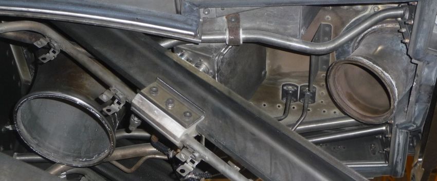
Dieter SCHOLZ                                                                               154

                                      1. INTRODUCTION
Cabin air ventilation in passenger aircraft is done with outside air. At cruise altitude, ambient
pressure is below cabin pressure. Hence, the outside air needs to be compressed before it is
delivered into the cabin. The most economic system principle simply uses the air that is
compressed in the engine compressor and taps some of it off as "bleed air". This principle is
explained in [1] (German) and [2] (English). In the context of contaminated cabin air the
background can be found in [3], [4], and [5]. Fig. 1 shows the contaminants and their routes
into the cabin. The individual routes are explained below.

                           Fig. 1 - Contaminants and their routes into the cabin

Route in blue: Seals at the engine bearings leak by design (Chapter 2). The leaking oil includes
metal nano particles (Chapter 3). The oil with metals finds its way into the engine compressor.
The same holds for the APU.
     Routes in green: Deicing fluid sprayed on the tail of the aircraft flows down along the
surface of the aft fuselage and surrounds the air intake of the APU at the bottom of the fuselage.
Hydraulic fluid leaks from the main landing gear bay and is directed along the outside of the
fuselage, to the APU air intake. In this way deicing fluid and hydraulic fluid can enter the APU
via its air intake (Chapter 4).
     Routes in red: Oil and metal from the engines find their way via bleed air into the cabin
(Chapter 3) and into the potable water (Chapter 3.1). Oil leaks also from the APU into the
APU bleed air and into the cabin. In addition, deicing fluids and hydraulic fluids make their
way via the APU bleed air into the cabin.
     Routes in purple: Deicing fluids, hydraulic fluids, oil, and fuel (from the fuel tank or
from the engine) drip on the ground. The engine ingests these liquids from the ground
(Chapter 5). Once in the engine compressor, the liquids find their way via the bleed air into
the cabin.
     Routes in orange: Exhaust gases from other aircraft are ingested. In case of a strong
tailwind on the ground or in case of reverse thrust at landing, the engine ingests its own
exhaust. Contaminates find their way via the bleed air into the cabin.
     HEPA filter: In the cabin, HEPA filter are part of the recirculation (Chapter 6). Standard
HEPA filters cannot mitigate the problem of oil contamination.

INCAS BULLETIN, Volume 14, Issue 1/ 2022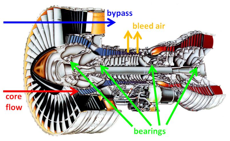
155          Routes of Aircraft Cabin Air Contamination from Engine Oil, Hydraulic and Deicing Fluid

                 2. JET ENGINE TECHNOLOGY AND RESULTS
The engine shaft is supported by lubricated bearings. Fig. 2 shows the location of the bearings
in a jet engine and the position, where the bleed air is tapped off for cabin ventilation.

                                Fig. 2 - Engine bearings and bleed air (based on [6])

The bearings are sealed against the air in the compressor usually with labyrinth seals, shown
in Fig. 3. Unfortunately, the jet engine seals leak oil by design in small quantities. Even more
so, the seals leak oil in certain flight phases, when they are worn out, or in failure cases.

                     Fig. 3 - Lubrication and sealing of engine bearings (based on [7])

Even in normal operation, the engine seals leak small quantities of oil. This follows from Fig. 3
and these observations:
     1. The "drain" discharges oil.
     2. The "dry cavity" contains oil.
     3. Air and oil leak from the bearing chamber into the air stream of the compressor and
        into the bleed air.

                                                                 INCAS BULLETIN, Volume 14, Issue 1/ 2022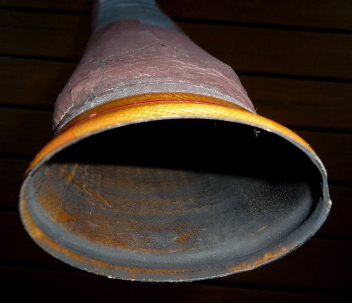
Dieter SCHOLZ                                                                                                 156

Accordingly, engines leak small amounts of oil by design. The oil with its toxic additives leaks
into the compressor. It is pyrolized at the high air temperatures in the compressor leaving
hundreds of organic substances behind some of which are toxic. Furthermore, the oil includes
toxic metal nanoparticles – normal debris from the engine. These metal nanoparticles from the
oil are finally found in the body of crew members as shown in the example of Fig. 4.

 Fig. 4 - Left: High-magnification image (1228x) of human fatty tissue of a cockpit crew member showing a 10-
 micron (top) and a 1-micron (bottom, left) brighter-looking metal particle. Right: The EDS (Energy-Dispersive
   X-ray spectroscopy) spectrum analyzes the brighter-looking metal particles from the left picture, indicating
 carbon (C), iron (FE), chromium (CR) and Oxygen (O), hence a stainless-steel composition ([8], Analysis 8 of
Table I, report written for client). The metal is probably debris from the engine transported with the oil into cabin
                                                    and cockpit air

         3. DISTRIBUTION OF ENGINE OIL WITH NANOPARTICLES
An alternative source for the compressed air is the Auxiliary Power Unit (APU). Like the
aircraft's jet engine, it is a gas turbine, built much in the same way when it comes to bearings
and seals. For this reason, also compressed air from the APU can get contaminated in the same
way (see Fig. 3). Fig. 5 shows the route of the engine oil into the cabin via bleed air from the
engines and compressed air from the APU.

                                   Fig. 5 - The route of engine oil into the cabin

The Fig. 6 to 9 show the inside of a cabin in a Cabin Air Contamination Event (CACE) due to
engine oil after a technical fault.
INCAS BULLETIN, Volume 14, Issue 1/ 2022
157            Routes of Aircraft Cabin Air Contamination from Engine Oil, Hydraulic and Deicing Fluid

   Fig. 6 - 2010-09-17, US Airways US-432, Boeing 757-200. Maui-bound flight enroute overhead the Pacific
     diverted to San Francisco (1200 nm). More: [9]. Picture source: Video: https://youtu.be/AZqeA32Em2s

Fig. 7 - 2018-12-10, Indigo flight 6E-237, Airbus A320neo, Jaipur to Kolkata, India. The smoke was traced down
to the engines (PW1127). This and more: [10]. Cause: Leakage of oil from the engine [11]. Picture source: Video:
                                         https://youtu.be/TO_FZ3L4yus

  Fig. 8 - 2019-08-22, Hawaiian Airlines HA47, A321neo. Emergency landing and evacuation after smoke on
 board. Cause: Seal failure in left engine. Picture source: Glen Westenskow. This picture and more: [12]. More
                                      also on https://purl.org/cabinair/HA47

 Fig. 9 - 2019-08-05, British Airways BA-422, Airbus A321. On a flight from London Heathrow to Valencia, the
      aircraft was descending towards Valencia when smoke appeared in the cabin. It followed an emergency
evacuation. The aircraft remained 9 days in Valencia and was subsequently ferried to London. After a total of 31
  days the aircraft returned back to service [13]. "It was found that no fire had occurred, but engine #2 (V2533,
    right hand) had lost all its oil. The engine was removed from the airframe and sent to the manufacturer for
thorough inspection." This and more on: [14]. Picture source: Lucy Brown. Video: https://youtu.be/tFsN0h09gAI

                                                                   INCAS BULLETIN, Volume 14, Issue 1/ 2022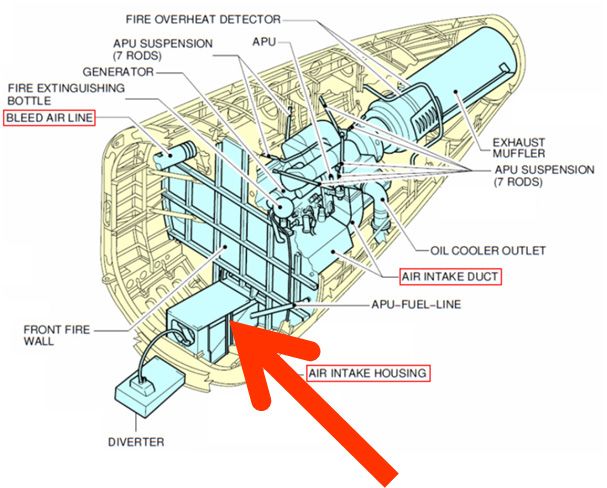
Dieter SCHOLZ                                                                                           158

    3.1 Engine Oil in the Potable Water
Compressed air from the engine is also used to pressurize the potable water tanks on some
aircraft like the Airbus A320 [15]. It has been observed that the potable water on board can
also be contaminated. Potable water contaminated by bleed air on an Airbus A320, is shown
in Fig. 10. It is the last water extracted from the tank before it is empty. This water is black,
probably from engine oil residue.
                                                      Fig. 10 - Potable water contaminated by bleed air on
                                                      an Airbus A320. This is the last water extracted from
                                                         the tank before it is empty. This water is black,
                                                      probably from engine oil residue. Picture source is a
                                                       Video: https://youtu.be/dlPOeudTTCI. The video is
                                                        explained: On the A320 the potable water tank is
                                                                   pressurized with bleed air.
                                                          On the A320 also the hydraulic reservoirs are
                                                     pressurized with bleed air. The bleed air presses on the
                                                      free surface of the hydraulic fluid and gets as such in
                                                      contact with it. The "mixture of hydraulic fluid vapor
                                                       and bleed air" is connected via bleed lines with the
                                                      potable water tanks. But flow of this mixture into the
                                                                 potable water tanks is unlikely:
                                                       • In flight, the "mixture of hydraulic fluid vapor and
                                                       bleed air" would need to flow upstream and opposite
                                                      sense through two check valves (which by design will
                                                      not happen in larger quantity) to get into the bleed line
                                                                       for water pressurization.
                                                       • However, on the ground (without bleed pressure),
                                                        the hydraulic fluid vapor and bleed air mixture can
                                                          flow downstream(!) but would still need to flow
                                                       opposite sense through two check valves (which by
                                                       design will not happen in larger quantity) to get into
                                                              the bleed line for water pressurization.

    3.2 Engine Oil Colors Bleed Air Ducts
                                   When an engine is taken off the aircraft, two air ducts
                                   become visible: the duct for the fan air and the duct for the
                                   bleed air. Fan air and bleed air ducts at the interface
                                   between engine and wing carry outside compressed air.
                                   Fig. 11 shows a diagram from the Airbus A320. The red line
                                   indicates the cut when separating the engine from the wing.
                                   The fan air is fresh outside air that has at best touched the fan
                                   blades (or the outlet guide vanes) on its way through the
                                   engine bypass.

                                       Fig. 11 - Fan air and bleed air taken off a jet engine. The red line
                                     indicates where the fan air duct and the bleed air duct are separated,
                                    when the engine is taken off. The diagram is a simplification based on a
                                         diagram explaining the pneumatic system (ATA 36) in [16]

INCAS BULLETIN, Volume 14, Issue 1/ 2022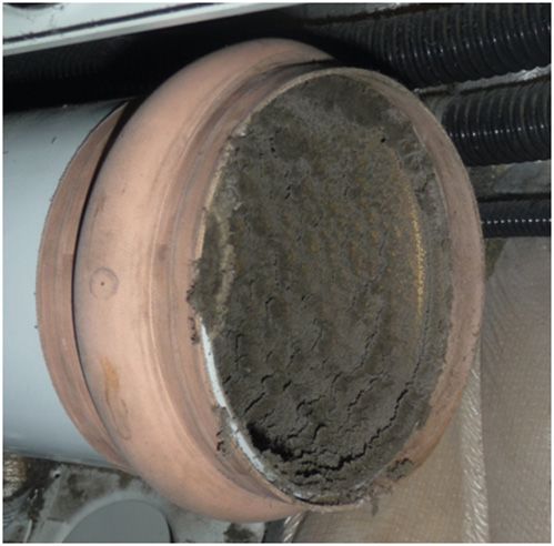
159            Routes of Aircraft Cabin Air Contamination from Engine Oil, Hydraulic and Deicing Fluid

On the other hand, the bleed air is fresh outside air that has gone through the core of the engine.
If everything were right, there should not be a difference depending on where the outside air
gets compressed. Unfortunately, there is a difference. Bleed air is potentially contaminated
with engine oil. This can be seen in Fig. 12. The fan air duct shows a normal metallic surface
color, whereas the bleed air duct at the engine interface appears brown. The bleed air
temperature at this point is about 300°C ... 400°C, the fan air is closer to ambient temperature.
Metal on its own does not turn to a brown color when heated to 400°C. The only explanation
with respect to the difference in the color of the two ducts is that the bleed air is covered by a
brown residue. Confirmation comes from touching the surface. If not deposited in the duct,
the substance causing the residue makes otherwise its way into the cabin. We know from
engineering (Fig. 3) that jet engine seals leak oil by design. Therefore, the brown residue in
the bleed air duct compared to the fan air duct is a confirmation that oil leakage takes place in
the engine.

           Fan Air

                                                                                    Bleed Air

          Fig. 12 - Bleed air duct with brown stain compared to a clean fan air duct on an Airbus A320

Ducting further downstream shows a black dry cover. The reason for the change in color seems
to result from the different air temperatures: 400°C at engine outlet and 200°C further
downstream behind the precooler. Fig. 13 shows a bleed air duct of a Boeing 737 with black
oil residue inside.

  Fig. 13 – Engine oil colors bleed air duct black (it is not just dark) from a Boeing 737. Picture source: Video:
                               https://vimeo.com/groups/617439/videos/345959025

                                                                     INCAS BULLETIN, Volume 14, Issue 1/ 2022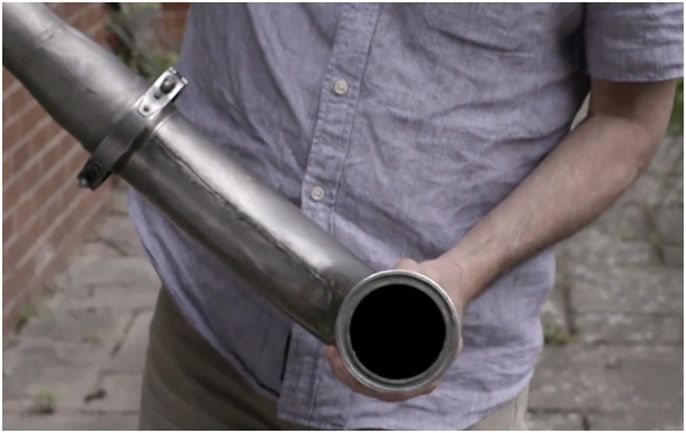
Dieter SCHOLZ                                                                                                 160

The water extractor is a part of the air conditioning pack. Fig. 14 shows the Airbus A320 water
extractor, which is part of the air conditioning packs. The inlet of the water extractor is covered
with black oily residue because the temperature is even lower at this point.

    Fig. 14 - Engine oil residue accumulates in the water extractor. The schematic on the right is from [17]

    3.3 Engine Oil Colors Cabin Air Ducts
                                                                The air conditioning air distribution
                                                                ducts in the cabin are black inside from
                                                                contaminated bleed air. Fig. 15 shows
                                                                the Airbus A320 air conditioning air
                                                                distribution duct in the cabin. The inside
                                                                is black from contaminated bleed air.

                                                                   Fig. 15 - Airbus A320 air conditioning air
                                                                          distribution duct in the cabin

Fig. 16 shows on the left side an unused duct supplied new. The right side of Fig. 16 shows
the same duct that had been installed downstream of the environmental control system air
conditioning packs on a BAe 146 passenger aircraft after 26061 flight hours.

                                                                                                Fig. 16 - Left:
                                                                                               Unused cabin air
                                                                                              duct. Right: Used
                                                                                              cabin air duct on a
                                                                                                  BAe 146
                                                                                              passenger aircraft
                                                                                                     [18]

INCAS BULLETIN, Volume 14, Issue 1/ 2022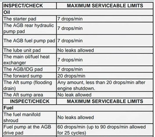
161 Routes of Aircraft Cabin Air Contamination from Engine Oil, Hydraulic and Deicing Fluid
Air ducts are even clean inside at the end of the aircraft's life, in areas where they are used
such that no bleed air flows through them. Such an example is shown in Fig. 17. The inside of
the air extract duct (located near the extract fan) is clean at the end of life of an Airbus A320,
because the duct is normally not fed with bleed air. This disproves the argument that all ducts
are black due to normal use over the course of decades in service.
Fig. 17 - Clean air duct at end of life of an Airbus A320
Flow limiters have been found in ducts of the air conditioning system clogged from engine oil.
Fig. 18 shows flow limiters clogged from pyrolyzed engine oil in ducts of the air conditioning
system of Boeing 757 aircraft with Rolls-Royce RB211-535E4 engines operated by Icelandair
[19] compared to a clean flow limiter (top, left).
Fig. 18 - Top left: Clean flow limiter in an air conditioning duct on an Airbus A320 (here in a dead-end duct
section installed for unknown reason) compared to flow limiters clogged from pyrolyzed engine oil in ducts of
the air conditioning system of Boeing 757 aircraft [19]
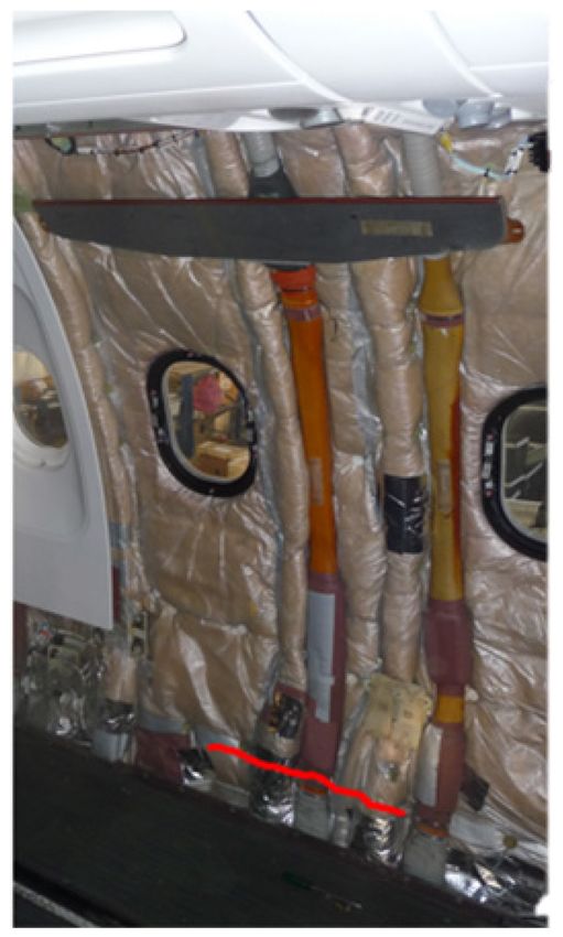
Fig. 19 shows the riser ducts and lower cabin air outlet on an Airbus A320 aircraft. The red
line in Fig. 19 close to the cabin floor indicates where the duct was separated and opened.
Looking down to the cabin floor shows a duct feeding the riser ducts. It is black inside from
INCAS BULLETIN, Volume 14, Issue 1/ 2022
Dieter SCHOLZ                                                                                            162

engine oil residue. Fig. 20 shows a view into the riser duct at that end, where it was separated
at the cabin floor. It is also black inside.
      It has been argued that on old aircraft, cabin air ducts could be black inside due to cigarette
smoke. This however is not likely for three reasons:
      1. The bans on inflight smoking have been introduced gradually around the world
beginning in the 1980s. An aircraft that is flying or is parted out today (like the one from which
most of the picture are taken) will most probably have not seen any onboard smoking.
      2. Air can only get into the cabin air ducts after it has be recirculated through the HEPA
filters, which would filter out smoke particles.
      3. Ducts are contaminated starting from the bleed air ducts connected with the engine.
Cigarette smoke would not explain contamination of these ducts.

                                           Fig. 19 - Left: Riser ducts and lower cabin air outlet on an
                                           Airbus A320 aircraft. The red line close to the cabin floor
                                            shows, where the riser ducts are attached to their supply
                                            duct. See: Video: https://youtu.be/jHGu83gC6V4. Top:
                                           View into the supply duct leading up into the riser duct on
                                           an Airbus A320. The inside is covered by a black residue

                                                                                  Fig. 20 - View into the
                                                                                  riser duct where it was
                                                                                   separated at the cabin
                                                                                     floor. It is covered
                                                                                  inside by black residue

INCAS BULLETIN, Volume 14, Issue 1/ 2022
163 Routes of Aircraft Cabin Air Contamination from Engine Oil, Hydraulic and Deicing Fluid
3.4 Engine Oil on Overhead Bins
Cleaning on top of the overhead bins of an Airbus A320 brings to light dirt that is clearly more
than dust. The black residue similar to that known from the ducts settles also on the bin surface,
as shown on the left side of Fig. 21. The right side of Fig. 21 shows an Airbus A320 cabin
cross section with the upper cabin air outlet releasing potentially contaminated air on top of
the overhead bins.
Fig. 21 - Left: Cleaning on top of the overhead bins of an Airbus A320 brings to light dirt that is clearly more
than dust. The black residue known from the ducts settles also on the bin surface. Picture source: Video:
https://youtu.be/uQfA_DiMBS8. Right: Airbus A320 cabin cross section with the upper cabin air outlet releasing
potentially contaminated air on top of the overhead bins (based on [17])
4. DISTRIBUTION OF HYDRAULIC AND DEICING FLUID
Fig. 22 - The route of hydraulic and deicing fluid into the cabin
INCAS BULLETIN, Volume 14, Issue 1/ 2022Dieter SCHOLZ 164
4.1 APU Air Intake
Deicing fluid and hydraulic fluid can find their way into the air conditioning system via the
APU air intake. The location of the APU air intake is shown in Fig. 23.
Fig. 23 - APU air intake [20]
The left side of the Fig. 24 shows the air intake of the A320 APU. Fence and deflector around
the APU air intake are clearly visible. These measures cannot fully prevent contaminants from
entering the APU. On the right side of Fig. 24 traces of contamination are clearly visible on
the lower part of the fuselage. Carried by the air flow in flight, the contaminants reach the
APU inlet.
Fig. 24 - Air intake of the A320 APU. Source of picture on the right: [21]
INCAS BULLETIN, Volume 14, Issue 1/ 2022165 Routes of Aircraft Cabin Air Contamination from Engine Oil, Hydraulic and Deicing Fluid
4.2 No “Zero Leakage” of Hydraulic Systems
Hydraulic systems are never leak free. A hydraulic seal drain system tries to collect hydraulic
fluid leaving the system with partial success. It is impossible to catch all leaking hydraulic
fluid. If the containers of the seal drain system are not emptied, they spill over. Either way, the
fluid finds its way to the APU inlet. Fig. 25 and 26 show the forward and aft collector tank of
the A320 hydraulic seal drain system.
Fig. 25 - Forward (left) and aft (right) collector tank of the A320 seal drain system [22] and [23]
Fig. 26 - Aft collector tank of the A320 seal drain
system, ATA 29-17. Forward and aft collector tanks
collect hydraulic fluid from leaking equipment in the
landing gear compartment, but spillover into the landing
gear compartment when full. The photo tries to explain,
what is meant with "the hydraulics industry must clean
up its messy image". In this old Airbus A320, all
surfaces in the landing gear bay are covered with a layer
of hydraulic fluid. Dirt accumulates on the sticky
surface. Logically, the hydraulic fluid is not confined to
the inside of the hydraulic bay, but continues the lower
side of the fuselage, if not cleaned constantly and finds
its way to the APU inlet
4.3 Aircraft Deicing
In Fig. 27 shows how deicing fluid is applied and how it covers the surface of an aircraft. The
purpose is to clean the aircraft from frost and snow and to protect it from further onset. Deicing
fluid can leak from the tail into the APU inlet as shown in Fig. 28.
Fig. 27 - Leakage of deicing fluid [24] Fig. 28 - Leakage of deicing fluid on the lower
side of the fuselage into the APU [25]
INCAS BULLETIN, Volume 14, Issue 1/ 2022Dieter SCHOLZ 166
5. DISTRIBUTION OF FLUIDS VIA AIRPORT SURFACES
Fuel and oil also leak down onto the airport surfaces. Fig. 29 shows the route of fluids down
to the ground and back into the engine.
Fig. 29 - The route of fluids down to the ground and back into the engine
5.1 Leak Limits of Aircraft Equipment
There are leak limits of aircraft equipment as shown in Fig. 30. These leak limits show that it
is normal for fluids to drip in smaller quantities on the ground. However, an airport sees many
airplanes dripping and it all adds up over weeks, months and years.
Fig. 30 - A320 leak limits for the CFM56-5B engine in drops per minute. Drops add up over time [26].
AGB: Accessory Gearbox. IDG: Integrated Drive Generator
5.2 Intake of Fluids by the Engine
Fluids that leak on the ground can be ingested by the engine from the ground and can enter the
air conditioning system from there. Fig. 31 shows the simulation of two intake vortices, one
of them as ground vortex. The rotation of the vortex is visible. Fig. 32 shows the same situation
in a photograph.
INCAS BULLETIN, Volume 14, Issue 1/ 2022167 Routes of Aircraft Cabin Air Contamination from Engine Oil, Hydraulic and Deicing Fluid
Fig. 31 - Simulation of two intake vortices, one of them as a ground vortex. The rotation of the vortex is visible.
Picture source: https://perma.cc/VH99-87XS
Fig. 32 - The ground vortex can also form between the ground and an engine on a high wing [27]
6. MORE CONTAMINATION
The location of the recirculation fan of an Airbus A320 is shown in Fig. 33. The face of the
recirculation fan of an Airbus A320 is covered by an oily black soft substance that can be
scraped off with a screwdriver (Fig. 34).
INCAS BULLETIN, Volume 14, Issue 1/ 2022Dieter SCHOLZ 168
Fig. 33 - The main component of the Airbus A320 recirculation system. View from the forward cargo
compartment looking aft. The wall panels in the cargo compartment are not installed. The support frames for the
wall panels are visible. Two HEPA filters and two recirculation fans are installed symmetrically
Fig. 34 - The recirculation fan of an Airbus A320 is covered by an oily black soft substance that can be scraped
off with a screw driver. Picture source: Video: https://youtu.be/jHGu83gC6V4. A disassembled recirculation fan
is shown on the right.
Fig. 35 shows the ambient air inlet in the cargo compartment of the Airbus A320 for cargo
compartment heating and ventilation. The inlet is full of moist dust.
Fig. 35 - The ambient air inlet in the cargo compartment of the Airbus A320 for cargo compartment heating and
ventilation. The inlet is full of moist dust
INCAS BULLETIN, Volume 14, Issue 1/ 2022169 Routes of Aircraft Cabin Air Contamination from Engine Oil, Hydraulic and Deicing Fluid
7. CONCLUSIONS
Pyrolized engine oil, hydraulic and deicing fluid as well as nanoparticles from engine debris
are problematic for human health. These substances can find their way via various routes into
cabin air and potable water on board of aircraft. Most discussed is the path of engine oil and
its additives via bleed air into the cabin air. But there are other substances, paths and sources
of leakage. The engineering assumption is that engine oil and hydraulic fluids operate in closed
systems. A detailed look shows however that this assumption is wrong. Nothing is perfect,
systems wear out or fail. No seal is fully tight. Fighting entropy does not work. Entropy is the
law of nature that states that disorder always increases, as shown in Fig. 36. This is the reason,
why it is fundamentally impossible to confine engine oil and hydraulic fluids to their
(predominantly) closed aircraft systems. This is why engine oil with metal nanoparticles
hydraulic fluids, and deicing fluids eventually go everywhere and finally into the human body.
Fig. 36 - Disorder always increases (based on https://perma.cc/A6KL-XS9R)
ACKNOWLEDGEMENTS
Hamburg University of Applied Sciences supported this research in several ways.
REFERENCES
[1] D. Scholz, Flugzeugsysteme. In: P. Horst, C. Rossow and K. Wolf (Eds.), Handbuch der Luftfahrzeugtechnik,
München, Germany, Carl Hanser, 2014. Available at https://doi.org/10.3139/9783446436046.007. Open
Access at http://handbuch.ProfScholz.de.
[2] D. Scholz, Aircraft Systems. In: M. F. Platzer and B. N. Agrawal (Eds.), Standard Handbook for Aerospace
Engineers, New York, McGraw-Hill and SAE International, pp. 13-112, 2018. Available at
https://www.sae.org/publications/books/content/jp-mgh-001. Open Access at (sample text)
https://purl.org/ProfScholz/publications/AircraftSystems.
[3] D. Scholz, Aircraft Cabin Air and Engine Oil – A Systems Engineering View, presented at Hamburg Aerospace
Lecture Series (DGLR, RAeS, VDI, ZAL, HAW Hamburg with VC and UFO), HAW Hamburg, 2017-04-
27. Available at https://doi.org/10.5281/zenodo.1237858.
[4] D. Scholz, Aircraft Cabin Air and Engine Oil – An Engineering View [Presentation]. In: International Aircraft
Cabin Air Conference 2017 (Imperial College London, 19.-20.09.2017), 2017. Available at
https://doi.org/10.5281/zenodo.4495496.
[5] D. Scholz, Aircraft Cabin Air and Engine Oil An Engineering View. In: Journal of Health and Pollution, vol.
9, no. 24 [Dec. 2019], pp. 93 - 98, International Aircraft Cabin Air Conference 2017, Imperial College
London, 19.-20.09.2017, 2019. Available at https://doi.org/10.5281/zenodo.3565834.
[6] * * * P&W, PW 4000 94 Inch Fan Engine, East Hartford, CT, USA, Raytheon Technologies Corporation,
Pratt & Whitney Division (P&W), 2014. Available at https://unitedtech.co/2J3FlIt. Archived at
https://perma.cc/6QJ6-BWUX.
INCAS BULLETIN, Volume 14, Issue 1/ 2022Dieter SCHOLZ 170
[7] * * * Exxon, Jet Engine Oil System, Part 2: Bearing Sump Lubrication, 2017. Available at
https://exxonmobil.co/2I6LNAV. Archived at https://perma.cc/RL7E-5XUPT.
[8] A. Gatti, S. Montanari, Evaluation of a Pathological Sample Through an Environmental Scanning Electron
Microscopy Investigation and an X-Ray Micro-Analysis, report 3/2019. Nanodiagnostics, Via E. Fermi,
1/L, 41057 San Vito di Spilamberto (Modena), Italia, 2019. https://www.nanodiagnostics.it.
[9] * * * AvHerald, Incident: Us Airways B752 over Pacific on Sep 17th 2010, Smoke in Cockpit, Salzburg, Austria,
NOMIS SOFT Datenverarbeitung, 2010. Available at https://avherald.com/h?article=4311269d. Archived
at https://perma.cc/C76K-TA4C
[10] * * * AvHerald, Incident: Indigo A20N at Kolkata on Dec 10th 2018, Smoke on Board, Salzburg, Austria,
NOMIS SOFT Datenverarbeitung, 2018. Available at https://avherald.com/h?article=4c16eec3. Archived
at https://perma.cc/UQ9A-QTDE.
[11] * * * Telegraph, Bearing-Oil Leak Blamed for Indigo Cabin Smoke, Kolkata, India, The Telegraph, 2018-12-
12. Available at https://bit.ly/2JHbqd0. Archived at https://perma.cc/59P9-CE8Y.
[12] * * * AvHerald, Accident: Hawaiian A21N near Honolulu on Aug 22nd 2019, Fumes and Smoke on Board
Prompt Evacuation, Salzburg, Austria, NOMIS SOFT Datenverarbeitung, 2019. Available at
https://avherald.com/h?article=4cbe89b0. Archived at https://perma.cc/T9P5-6Z9A.
[13] T. Ayan, Analyse der Liegezeiten von Passagierflugzeugen nach Fume Events mittels Flugverfolgung, Project,
Hamburg University of Applied Science, Aircraft Design and Systems Group (AERO), 2000. Available at
https://nbn-resolving.org/urn:nbn:de:gbv:18302-aero2020-01-15.016.
[14] * * * AvHerald, Accident: British Airways A321 at Valencia on Aug 5th 2019, Smoke on Board, Salzburg,
Austria, NOMIS SOFT Datenverarbeitung, 2019. Available at https://avherald.com/h?article=4cb3a0d2.
Archived at https://perma.cc/MMA9-FZND.
[15] D. Scholz, Aircraft Cabin Air & Water Contamination/Quality – An Aircraft Systems Engineering Perspective.
Global Cabin Air Quality Executive (QCAQE), Seventh Annual Forum and Information Exchange,
London, 31st March – 2nd April 2014. Available at https://purl.org/cabinair/AirAndWater.
[16] * * * Airbus, A320 Fligth Crew Operating Manual (FCOM):Vol. 1 – Systems Description, 1999. Available at
https://bit.ly/3pY1cVn (AVSIM.su, A320 FCOM, Page). Archived at https://perma.cc/EW5T-VSSE.
[17] * * * Airbus, A319/A320/A321 Aircraft Maintenance Manual (ADRES) [CD], Blagnac, France, Airbus
Industrie, Customer Service Directorate, 1999.
[18] * * * CAA, Cabin Air Quality, Gatwick Airport, West Sussex, UK, Civil Aviation Authority (CAA), CAA
PAPER 2004/04, 2004. Available at https://publicapps.caa.co.uk/docs/33/CAPAP2004_04.PDF. Archived
at https://perma.cc/MY6M-35Z5
[19] R. Hansen [Icelandair], Suspected Air Quality Problems on Board – Experiences and Actions In: International
Aircraft Cabin Air Conference 2017 (Imperial College London, 19.20.09.2017), 2019. Available at
https://doi.org/10.5281/zenodo.4464537.
[20] * * * Airbus, A320 – Aircraft Characteristics Airport and Maintenance Planning, AIRBUS S.A.S., Customer
Services, Technical Data Support and Services, 31707 Blagnac Cedex, France, Issue: Sep 30/85, Rev: Dec
01/20, 2020. Available at https://bit.ly/37ctHaR (Aircraft Characteristics Homepage). Archived at
https://perma.cc/ARS5-AN5P.
[21] * * * Airbus, Digest for Smoke, Odors and Fumes (SOF): In Service Information, Ref.: ISI 21.00.00139,
Blagnac, France, Airbus, 2019. Archived at https://perma.cc/W3U7-C4HM.
[22] * * * Mekanikong, Hydraulic Forward Collector Tank, Facebook, 2019-06-11. Archived at
https://perma.cc/9MCZ-R5NR?type=image.
[23] * * * Mekanikong, Hydraulic Forward Collector Tank, Facebook, 2019-06-11. Archived at
https://perma.cc/YXM4-MTZR?type=image.
[24] I. Petchenik [Flightradar24], Ready for Winter – A Look at Aircraft Deicing, Flightradar24 Blog, 2015.
Available at https://www.flightradar24.com/blog/ready-for-winter-a-look-at-aircraft deicing. Archived at
https://perma.cc/TGQ7-KXFM?type=image.
[25] L. Vera-Barcelo, A Clean APU Means Clean Cabin Air, In: AIRBUS, FAST #52: Airbus Technical Magazine,
2013, August. Available at https://bit.ly/341o5OT (FAST Homepage). Archived at
https://perma.cc/5AW9-D5CW.
[26] * * * Mekanikong, A320 Engine Leak Limits, CFM-56, Facebook, 2019-05-14. Archived at
https://perma.cc/9SKM-88KU?type=image.
[27] P. RN Childs, Jet Engine Internal Air Systems [Presentation]. In: International Aircraft Cabin Air Conference
2017 (Imperial College London, 19.-20.09.2017), 2017. Available at
https://doi.org/10.5281/zenodo.4501577.
INCAS BULLETIN, Volume 14, Issue 1/ 2022You can also read