RPS 1000 RPS 2500 RPS 5000 RPS 10000 - USER MANUAL MANUALE UTENTE - Elettrotest
←
→
Page content transcription
If your browser does not render page correctly, please read the page content below
RPS 1000
                                                RPS 2500
                                                RPS 5000
                                                RPS 10000

                 USER MANUAL
                 MANUALE UTENTE

USER MANUAL RPS/M - 62000582 Rel.2.A – 24/02/2020
SAFETY WARNINGS

The manufacturer urges users to read the user manual for our products before installation.
The installation must be carried out by qualified technical staff. The non-observance of the
warnings in this manual can cause electric shocks, even fatal ones.

Please find below some general safety warnings.

    • This equipment must be connected to the mains supply using the appropriate safety
      devices. Please consult the relevant paragraph 2, in this manual.
    • RPS must be connected to safety ground through the apposite connections. The non-
      observance or the degradation of this earth connection can lead to electric shocks, even
      fatal ones. As regards the correct connection modes, please refer to the information
      contained in paragraph 2.
    • Disconnect RPS from the mains before any work on the equipment and on the connected
      power loads.
    • Before touching the load or the output connector make sure that the power supply on the
      device has been disconnected for at least 5 minutes. This is the time necessary in order for
      the capacitors inside the device to discharge. The non-observance of this discharge time
      can lead to electric shocks, even fatal ones.
    • The output of RPS is not isolated respect to the main power supply and so NONE OF THE
      TWO OUTPUT PHASES CAN BE CONNECTED TO THE GROUND.
    • Avoid heavy shocks to the equipment (especially during transport) or exposure to extreme
      weather conditions.
    • Any damage to the product due to transportation, incorrect installation or improper use is
      not covered by the guarantee supplied by the manufacturer.
    • Do not use the equipment in explosive environments or in the presence of dust, acids or
      corrosive and/or inflammable gases.
    • Tampering with or dismantling any component in the equipment will void the warranty
      automatically.
    • Do not operate or store under conditions where condensing may occur or where
      conductive debris may enter in the case.

                 The manufacturer declines all responsibility for damage to people or things caused
                 by an improper use of its products.

                 ELECTRIC RISK
                 There are dangerous voltages inside RPS and over the output connector.
                 The non-observance of the warnings suggest in this manual can lead to electric
                 shocks, even fatal ones.

                 OVERHEATING RISK
                 In the case of a ventilation system failure, the metal parts of the inverter may reach
                 high temperatures (in some cases higher than 70°C).

                                                                                                          1
USER MANUAL RPS - 62000582 Rel.2.A – 24/02/2020
DISPOSAL

          INFORMATION FOR USERS ON THE CORRECT HANDLING OF WASTE
                ELECTRICAL AND ELECTRONIC EQUIPMENT (WEEE)

In reference to European Union directive 2012/19/EU issued on 24 July 2012 and the related
national legislation, please note that:

    • WEEE cannot be disposed of as municipal waste and such waste must be collected and
      disposed of separately;
    • the public or private waste collection systems defined by local legislation must be used. In
      addition, the equipment can be returned to the manufacturer at the end of its working life
      when buying new equipment;
    • the equipment may contain hazardous substances: the improper use or incorrect disposal
      of such may have negative effects on human health and on the environment;
    • the symbol (crossed-out wheeled bin) shown on the product or on the packaging and on
      the instruction sheet indicates that the equipment must be disposed of separately;
    • in the event of illegal disposal of electrical and electronic waste, the penalties are specified
      by local waste disposal legislation.

                                                                                                    2
USER MANUAL RPS - 62000582 Rel.2.A – 24/02/2020
INDEX
1.  INTRODUCTION ............................................................................................................................ 4
  1.1. MAIN FEATURES .................................................................................................................... 4
    1.1.1. Output voltage ............................................................................................................... 4
    1.1.2. Output frequency ........................................................................................................... 4
    1.1.3. User interface................................................................................................................. 4
    1.1.4. General performances ................................................................................................... 5
    1.1.5. General specifications .................................................................................................... 5
  1.2. MODELS ................................................................................................................................. 5
2. INSTALLATION .............................................................................................................................. 6
  2.1. GENERAL NOTES .................................................................................................................... 6
    2.1.1. RPS 1000......................................................................................................................... 6
    2.1.2. RPS 2500 and RPS 5000.................................................................................................. 8
  2.2. FUSES ..................................................................................................................................... 9
  2.3. RCD PROTECTION .................................................................................................................. 9
  2.4. MAGNETO-THERMAL PROTECTION ...................................................................................... 9
  2.5. WIRING DIAGRAM ............................................................................................................... 10
    2.5.1. Single phase device ...................................................................................................... 10
    2.5.2. Three-phase device ...................................................................................................... 10
  2.6. POWER ON .......................................................................................................................... 10
3. FUNCTIONS ................................................................................................................................ 11
  3.1. VOLTAGE FEEDBACK ............................................................................................................ 11
  3.2. MAXIMUM OUTPUT CURRENT ............................................................................................ 11
    3.2.1. RPS 1000....................................................................................................................... 11
    3.2.2. RPS 2500....................................................................................................................... 12
    3.2.3. RPS 5000....................................................................................................................... 12
    3.2.4. RPS 10000..................................................................................................................... 12
  3.3. CURRENT LIMITATION MODE.............................................................................................. 13
    3.3.1. Peak Limitation Mode .................................................................................................. 13
    3.3.2. Average Limitation Mode ............................................................................................ 14
    3.3.3. Limitation Setting ......................................................................................................... 15
  3.4. OUTPUT SWITCH ................................................................................................................. 15
4. REMOTE CONTROL ..................................................................................................................... 16
  4.1. SERIAL REMOTE CONTROL .................................................................................................. 16
    4.1.1. Control software .......................................................................................................... 16
    4.1.2. Serial cable ................................................................................................................... 16
  4.2. ANALOG REMOTE CONTROL ............................................................................................... 16
    4.2.1. Analog interface ........................................................................................................... 16
    4.2.2. Performances ............................................................................................................... 18
5. ALARMS ...................................................................................................................................... 19
  5.1. SUPPLY ALARMS .................................................................................................................. 19
  5.2. SYSTEM ALARMS ................................................................................................................. 19
  5.3. CURRENT ALARM................................................................................................................. 19
  5.4. VOLTAGE ALARM ................................................................................................................. 20
6. TECHNICAL SPECIFICATIONS ...................................................................................................... 21
  6.1. DATA SHEET ......................................................................................................................... 21
  6.2. MECHANICAL DRAWINGS.................................................................................................... 22
    6.2.1. RPS 1000....................................................................................................................... 22
    6.2.2. RPS 2500 e RPS 5000 .................................................................................................... 23

                                                                                                                                                  3
USER MANUAL RPS - 62000582 Rel.2.A – 24/02/2020
1. INTRODUCTION
RPS is a power source that supplies a sinusoidal and stable voltage. Its output voltage is adjustable
in frequency and amplitude.

1.1.     MAIN FEATURES

1.1.1. Output voltage

The output voltage is guaranteed perfectly sinusoidal, with a distortion of less than 0.3%
regardless of the load. The value of output voltage is kept perfectly stable within 0.1% regardless
of the load.
RPS is also able to compensate for possible voltage drops on the output wires, ensuring that the
exact required voltage is provided to the load.
The load that RPS is able to drive can vary from a pure capacity to a pure inductance, but also up
to non symmetrical current loads, as, for instance, a single half wave rectifier.
The output voltage is adjustable with continuity from zero to full scale. Furthermore, RPS is
capable to keep the voltage stable with time variable loads, as for example the pulsating loads. In
fact RPS recovers the distortion of the waveform within 0.3% and the amplitude of the voltage
within 0.1% in less than half period.
Furthermore, RPS can bear a short-circuit for an indefinite time without suffering any
consequence.

THE OUTPUT OF RPS IS NOT ISOLATED RESPECT TO THE MAIN POWER SUPPLY

NONE OF THE TWO OUTPUT PHASES CAN BE CONNECTED TO THE GROUND

1.1.2. Output frequency

RPS allows the regulation of the output frequency from 10 Hz to 80 Hz. The output frequency can
be adjusted with continuity into the regulation range and it has a stability of 0.01% regards to set
frequency.

1.1.3. User interface

RPS can be remotely controlled both via analog interface and via serial communication. RPS allows
various usage selections: wires drop compensation, working frequency, output DC, output AC. RPS
gives the user clear information on the status of the output. It is monitored both the set voltage
and the set frequency. The output voltage can be remotely read with a precision of 0.3% f.s..
The user is also warned in case of overcurrent obtainable by the RPS, or in case of high loss on the
wires, that should not exceed 5% of the set voltage.

                                                                                                       4
USER MANUAL RPS - 62000582 Rel.2.A – 24/02/2020
1.1.4. General performances

All the following features are valid in the normal operation mode. They are not valid during the
output current limitation.

                                     PARAMETER                                    VALUE
               Distortion of the output waveform (1)
2. INSTALLATION
                The output of RPS is NOT isolated respect to the main power supply.
                NONE OF THE TWO OUTPUT PHASES CAN BE CONNECTED TO THE GROUND.

2.1.     GENERAL NOTES

2.1.1. RPS 1000

    • Connect one supplying cable 2PH+G (standard IEC cable) of suitable section (minimum
      section 3x1.5 mm2).
    • Check that Live and Neutral cables are correctly connected to the respective phases of the
      supply and not reversed.
    • Protect the input line with the circuit breakers presented in paragraph 2 (INSTALLATION).
    • Connect load cables to the output connector. Use an appropriate section according to the
      maximum load tolerable by the RPS.
    • Put the ferrite core on the load cable close to RPS.
    • Optionally: connect the sense wires.
    • Keep front area free for ventilation.
    • When RPS is mounted inside a cabinet you must install a forced ventilation in order to
      expel the hot air.
    • Never lay power cables (including the electrical cables) and probe signal cables in the same
      conduits.
    • Cleaning the device: when cleaning the device do not use ethyl alcohol, hydrocarbons
      (petrol), water, detergents, ammonia and derivatives. Use only a dry cloth.

If RPS 1000 is installed in a dusty ambient it’s recommended to purchase the optional anti-dust
filter (cod.99997545).

       INPUT CONNECTOR                            OUTPUT CONNECTOR                 FERRITE BEAD

                                                                                                6
USER MANUAL RPS - 62000582 Rel.2.A – 24/02/2020
INDEX                     DESCRIPTION
                                 1                 Serial 9 poles connector
                                 2                 Power output connector
                                 3                         Output air
                                 4                  Power input connector
                                 5                     Earth connector
                                 6                        Analog port
                                 7                          Input air
                                 8                Anti-Dust filter connection

                                                                                7
USER MANUAL RPS - 62000582 Rel.2.A – 24/02/2020
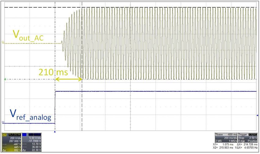
2.1.2. RPS 2500 and RPS 5000

    • Connect one supplying cable 2PH+G of suitable section (minimum section 3x4 mm2).
    • Protect the input line with the circuit breakers presented in paragraph 2 (INSTALLATION).
    • Connect load cables to the output connector. Use an appropriate sections according to the
      maximum load tolerable by the RPS.
    • Optionally: connect the sense wires.
    • Keep front area free for ventilation.
    • When RPS is mounted inside a cabinet you must install a forced ventilation in order to
      expel the hot air.
    • Never lay power cables (including the electrical cables) and probe signal cables in the same
      conduits.
    • Cleaning the device: when cleaning the device do not use ethyl alcohol, hydrocarbons
      (petrol), water, detergents, ammonia and derivatives. Use only a dry cloth.

                            INDICE                              DESCRIZIONE
                                1                                    Switch
                                2                                     Fuse
                                3                                   Input air
                                4                          Serial 9 poles connector
                                5                                 Analog port
                                6                          Power output connector
                                7                              Sense connector
                                8                           Power input connector
                                9                              Earth connector
                                10                                 Output air

                                                                                                8
USER MANUAL RPS - 62000582 Rel.2.A – 24/02/2020
2.2.     FUSES

Fuses can be used to protect power line of the RPS. It's recommended to use delayed fuses
according to the nominal input characteristic (see section 6.1).

2.3.     RCD PROTECTION

A residual-current device (RCD), or residual-current circuit breaker (RCCB), is a device that
instantly breaks an electric circuit to prevent serious harm from an ongoing electric shock.
It's recommended to use B type RCD with a earth leakage current of 30 mA according to the
nominal input characteristic (see section 6.1).

2.4.     MAGNETO-THERMAL PROTECTION

The Magneto-thermal circuit breaker protect the input line from short circuits. Generally depends
on the load and on the connection (section and length of the cable).
It is recommended to use a magneto-thermal protection with type C curve according to the
nominal input characteristic (see section 6.1).

                                                                                                9
USER MANUAL RPS - 62000582 Rel.2.A – 24/02/2020
2.5. WIRING DIAGRAM
2.5.1. Single phase device
2.5.2. Three-phase device
2.6. POWER ON
Some RPS models don't have power on switch (see section 2.1).In this case when the input
connector receives power, RPS turns on. In any case, RPS needs (after power on) less than 10
seconds to be ready.
10
USER MANUAL RPS - 62000582 Rel.2.A – 24/02/20203. FUNCTIONS
3.1. VOLTAGE FEEDBACK
The output voltage stabilization works the same in both the 2-wire and in the 4-wire output
configurations.
The 4-wire configuration can be used with a long-distance outlet and can compensate the voltage
drop due to cable connections.
To work in 4WIRE configuration, you must perform the wiring as shown in the figure below and
set "4WIRE" mode via remote control.
RPS compensates the voltage drop on the connections up to 5% of the set voltage.
To prevent any overheating of the line, when the limit has been exceeded, RPS does not guarantee
that the value of output voltage is equal to the voltage set. In this case it displays an error signal
(see the paragraph VOLTAGE ALARM).
3.2. MAXIMUM OUTPUT CURRENT
3.2.1. RPS 1000
CONTINUOUS OPERATION
MAX CORRENT MAX POWER
PORT DC 50Hz 60Hz LOAD PORT DC 50Hz 60Hz LOAD
300 - 2,7 A 2,6 A CAP. 300 - 811 VA 768 VA CAP.
300 - 4,1 A 4,3 A IND. 300 - 1235 VA 1277 VA IND.
300 3,4 A 3,3 A 3,3 A RES. 300 1020 VA 1001 VA 991 VA RES.
IMPULSIVE OPERATION (MAX 3 SECONDS)
MAX CORRENT MAX POWER
PORT DC 50Hz 60Hz LOAD PORT DC 50Hz 60Hz LOAD
300 - 6,2 A 6,1 A CAP. 300 - 1862 VA 1820 VA CAP.
300 - 7,6 A 7,8 A IND. 300 - 1235 VA 2329 VA IND.
300 6,9 A 6,9 A 6,9 A RES. 300 2064 VA 2064 VA 2059 VA RES.
11
USER MANUAL RPS - 62000582 Rel.2.A – 24/02/20203.2.2. RPS 2500
CONTINUOUS OPERATION
MAX CORRENT MAX POWER
PORT DC 50Hz 60Hz LOAD PORT DC 50Hz 60Hz LOAD
300 - 6,2 A 5,6 A CAP. 300 - 1858 VA 1688 VA CAP.
300 - 11,8 A 12,4 A IND. 300 - 3554 VA 3724 VA IND.
300 9A 8,6 A 8,4 A RES. 300 2706 VA 2570 VA 2507 VA RES.
IMPULSIVE OPERATION (MAX 3 SECONDS)
MAX CORRENT MAX POWER
PORT DC 50Hz 60Hz LOAD PORT DC 50Hz 60Hz LOAD
300 - 14,3A 13,8 A CAP. 300 - 4301 VA 4131 VA CAP.
300 - 20,0 A 20,6 A IND. 300 - 5997 VA 6167 VA IND.
300 18,0 A 16,9 A 16,8 A RES. 300 5149 VA 5079 VA 5047 VA RES.
3.2.3. RPS 5000
CONTINUOUS OPERATION
MAX CORRENT MAX POWER
PORT DC 50Hz 60Hz LOAD PORT DC 50Hz 60Hz LOAD
300 - 13,9 A 13,3 A CAP. 300 - 4162 VA 3992 VA CAP.
300 - 19,5 A 20,1 A IND. 300 - 5858 VA 6028 VA IND.
300 16,7 A 16,5 A 16,4 A RES. 300 5016 VA 4938 VA 4906 VA RES.
IMPULSIVE OPERATION (MAX 3 SECONDS)
MAX CURRENT MAX POWER
PORT DC 50Hz 60Hz LOAD PORT DC 50Hz 60Hz LOAD
300 - 30,5 A 29,9 A CAP. 300 - 9151 VA 8981 VA CAP.
300 - 36,2 A 36,7 A IND. 300 - 10847 VA 11017 VA IND.
300 33,0 A 33,2 A 33,2 A RES. 300 10000 VA 9963 VA 9947 VA RES.
3.2.4. RPS 10000
CONTINUOUS OPERATION
MAX CORRENT MAX POWER
PORT DC 50Hz 60Hz LOAD PORT DC 50Hz 60Hz LOAD
300 - 23,8 A 22,4 A CAP. 300 - 7152 VA 6728 VA CAP.
300 - 38,0 A 39,4 A IND. 300 - 11394 VA 11818 VA IND.
300 30,9 A 30,1 A 29,7 A RES. 300 9273 VA 9027 VA 8917 VA RES.
IMPULSIVE OPERATION (MAX 3 SECONDS)
MAX CURRENT MAX POWER
PORT DC 50Hz 60Hz LOAD PORT DC 50Hz 60Hz LOAD
300 - 57,3 A 55,8 A CAP. 300 - 17177 VA 16753 VA CAP.
300 - 71,4 A 72,8 A IND. 300 - 21418 VA 21842 VA IND.
300 64,3 A 63,9 A 63,8 A RES. 300 19298 VA 19181 VA 19129 VA RES.
12
USER MANUAL RPS - 62000582 Rel.2.A – 24/02/20203.3. CURRENT LIMITATION MODE
3.3.1. Peak Limitation Mode
Output current is limited instantaneously without delay at the limitation set. Only an initial
transient peak remains, due to the output capacitor discharge.
13
USER MANUAL RPS - 62000582 Rel.2.A – 24/02/20203.3.2. Average Limitation Mode
Output current is limited with a linear trend during a specific time (tAVG) in order to reach the
limitation set. TAVG time depends on how much the set average limit is exceeded (see chart below).
Limitations is enable both AC and DC mode
14
USER MANUAL RPS - 62000582 Rel.2.A – 24/02/20203.3.3. Limitation Setting
Both peak and average limitation can be set via serial command. Limits must be included in the
range [500,4095]. Values less than 500 are considered 500 by default (minimum value).
The factory values for both limitations are 4095. For further information please read the
programming manual.
3.4. OUTPUT SWITCH
It’s possible to open or close the output switch both by serial command and digital input. Before
opening the switch, the output voltage is switched to zero to safeguard the switch. Similarly, the
closing is done with zero voltage. Afterwards, the output will reach the set value through a voltage
ramp (set via serial commands).
The turn off of the output switch does not allow operations on the EUT connections.
15
USER MANUAL RPS - 62000582 Rel.2.A – 24/02/20204. REMOTE CONTROL
4.1. SERIAL REMOTE CONTROL
4.1.1. Control software
RPS can be remotely controlled via RS232 communication according to a copyrighted free
protocol. For further details on protocol, see the specific manual.
Parameters for serial connection:
BAUD RATE: 19200 (in standard version)
DATA BITS: 8
STOP BITS: 1
4.1.2. Serial cable
Use a serial cable according to the standard defined in the figure below.
WIRING CONNESSION
PC RPS
DB9 Poles Female DB9 Poles Male
2 2
3 3
5 5
4.2. ANALOG REMOTE CONTROL
4.2.1. Analog interface
RPS can be controlled by analog interface:
16
USER MANUAL RPS - 62000582 Rel.2.A – 24/02/2020Pin Nome Descrizione Livelli
1 +5V Power supply (Max 40mA) Respect to GND
2 Ref. analog Pwm or analog input 0-10V (respect to GND)
3 50/60 Hz Digital input 0V (50Hz) – 5V (60Hz)
4 Output relay Digital input 0V (Off) – 5V (On)
5 DC/AC Digital input 0V (AC) – 5V (DC)
6 Alarm Digital output 0V (no alarm) 5V (alarm)
Square waveform synchronized to
7 Synchronism Digital output
output voltage (0-5V).
8 Enable Digital output 0V (not enabled) 5V (enabled)
9 GND Ground
All the signals in the analog interface (both analog and digital) are referred to GND (9th pin of the
connector).
Input circuit of “Ref analog” signal
Digital input circuit Digital output circuit
17
USER MANUAL RPS - 62000582 Rel.2.A – 24/02/20204.2.2. Performances
Delay time between analog input and RPS output is about 200ms.
DELAY TIME IN DC MODE
DELAY TIME IN AC MODE
18
USER MANUAL RPS - 62000582 Rel.2.A – 24/02/20205. ALARMS
5.1. SUPPLY ALARMS
RPS can work with ±10% network voltage variations. If these RPS limits are exceeded, the RPS
stops and a special alarm is generated. In this case RPS can be unlocked via serial command
(SOFTWARE RESET) or by turning the machine off and on again.
If the supply voltage is too low RPS stops and outputs UNDERVOLTAGE alarm.
If the supply voltage is too high RPS stops and outputs OVERVOLTAGE alarm.
If the supply phases have been inverted, both the UNDERVOLTAGE and OVERVOLTAGE alarms
are generated. Check section 2.1 and invert the phases on the input connector.
5.2. SYSTEM ALARMS
Also in case of hardware failure of the inner inverter, RPS stops and generates a special alarm
(INVERTER). To reset RPS use the same method described for supply alarms. In case of high
temperature inside RPS, it stops and a special error is generated (OVERTEMP).
To reset the machine, turn it off and wait for a few minutes to cool the system. After that turn it
on again.
5.3. CURRENT ALARM
RPS controls the output current. RPS therefore allows for an output short circuit for an indefinite
time. In the case of loads that need a current higher than the rated one, RPS operates an output
current limitation. When this limitation occurs, a special alarm is generated (LIMIT OUTX).
In case of current limitation, the output sinusoidal wave is not guaranteed. Output can present
an harmonic distortion.
Nonlinear loads that require a power less than the maximum admitted from RPS with a very high
crest factor current can generate a current limitation as well.
If RPS is operating in current limitation, it maintains the RMS output voltage equal to the set value
until a special voltage alarm is generated (see VOLTAGE ALARM).
19
USER MANUAL RPS - 62000582 Rel.2.A – 24/02/2020CURRENT ALARM does not cause any stop.
5.4. VOLTAGE ALARM
RPS controls, in addition to the harmonic distortion, the RMS value of the output voltage both in
2WIRE and in 4WIRE configuration.
If the output voltage is not equal to the set value, a special alarm is generated (MAX DV OUTX).
VOLTAGE ALARM does not cause any stop.
20
USER MANUAL RPS - 62000582 Rel.2.A – 24/02/20206. TECHNICAL SPECIFICATIONS
6.1. DATA SHEET
MODEL 1000 2500 5000 10000
Power supply 1PH 230Vac ±10% 1PH 230Vac ±10% 1PH 230Vac ±10% 3PH+N 400Vac ±10%
Power 1000VA 2500VA 5000VA 10000VA
International IP20 IP20 IP20 IP20
Protection
Pollution degree 3 3 3 3
Overvoltage Category II Category II Category II Category II
category
Maximum input 7,5 Arms 18 Arms 35 Arms 24 Arms / 41 Arms
current on neutral
Input frequency 50Hz – 60Hz 50Hz – 60Hz 50Hz – 60Hz 50Hz – 60Hz
Output type Single phase Single phase Single phase Single phase
Output isolation Not isolated Not isolated Not isolated Not isolated
Maximum output 300 V 300 V 300 V 300 V
voltage
Maximum output 3,3 A 8,3 A 16,7 A 30,1 A
current (RMS)
Maximum output 6,9 A 16,7 A 33,4 A 64,3 A
inrush current (3 sec)
Output frequency DC, 10Hz – 80Hz (1) DC, 10Hz – 80Hz (1) DC, 10Hz – 80Hz (1) DC, 10Hz – 80Hz (1)
range
Dimensions 2U: 450:440 (2) 4U: 450:540 (2) 4U: 450:540 (2) 6U: 450:540 (2)
Weight 12 kg 25 kg 25 kg 48 kg
Protections OVP,UVP,OTP,OCP OVP,UVP,OTP,OCP OVP,UVP,OTP,OCP OVP,UVP,OTP,OCP
Operating 0 / +35 °C 0 / +35 °C 0 / +35 °C 0 / +35 °C
temperature
Storage temperature -20 / +70 °C -20 / +70 °C -20 / +70 °C -20 / +70 °C
RS232 Yes Yes Yes Yes
RS485 Option Option Option Option
LAN Option Option Option Option
Output DC Yes Yes Yes Yes
Digital IO Yes (3) Yes (3) Yes (3) Yes (3)
Safety certification EN 61010-1 EN 61010-1 EN 61010-1 EN 61010-1
EMC certification EN 61000-6-2 (4) EN 61000-6-2 (4) EN 61000-6-2 (4) EN 61000-6-2 (4)
EN 61000-6-4 (5) EN 61000-6-4 (5) EN 61000-6-4 (5) EN 61000-6-4 (5)
(1)
Frequency can be set up to 320Hz in derating power mode.
(2)
Dimension with connectors.
(3)
See section 4.2.
(4)
Immunity: industrial environment.
(5)
Emission: industrial environment.
21
USER MANUAL RPS - 62000582 Rel.2.A – 24/02/20206.2. MECHANICAL DRAWINGS
6.2.1. RPS 1000
(*) without connector.
22
USER MANUAL RPS - 62000582 Rel.2.A – 24/02/20206.2.2. RPS 2500 e RPS 5000
(*) with connector.
23
USER MANUAL RPS - 62000582 Rel.2.A – 24/02/2020Elettrotest Spa is committed to a program of continuous improvement of products and
information to the customer.
Therefore, the company reserves the right to make changes to the documentation and
specifications without notice and assumes no responsibility for any incorrect information.
Rev. Date Description
2.A 24/02/20 Anti-Dust filter installation notes
2.0 12/10/18 Introduced new models (2.5K/5K/10K)
1.0 15/03/18 Analog port implementation
0.0 06/10/17 First revision.
24
USER MANUAL RPS - 62000582 Rel.2.A – 24/02/2020AVVERTENZE PER LA SICUREZZA
Il costruttore raccomanda di leggere attentamente il manuale d’istruzione dei suoi prodotti prima
di procedere con la loro installazione.
L’installazione deve essere eseguita da personale tecnico qualificato. L’inosservanza delle
raccomandazioni riportate in questo manuale può causare shock elettrici anche mortali.
Di seguito sono riportate alcune avvertenze generali in merito alla sicurezza.
• Il dispositivo deve essere collegato all’alimentazione di rete tramite degli appositi
dispositivi di protezione. A tale scopo si consulti il paragrafo 2.
• RPS deve essere collegato a terra tramite le apposite connessioni. Il non rispetto o l’usura
di questo collegamento può portare a shock elettrico anche mortale. Per le modalità di
collegamento fare riferimento a quanto indicato nel paragrafo 2.
• Disconnettere RPS dall’alimentazione elettrica prima di ogni intervento
sull’apparecchiatura e sui carichi ad essa collegati.
• Prima di toccare il carico o la morsettiera di uscita assicurarsi che l’alimentazione del
dispositivo sia disconnessa da almeno 5 minuti. Questo è il tempo necessario affinché si
scarichino i condensatori presenti all’interno. Il non rispetto di questo tempo può portare a
shock elettrici anche mortali.
• Questa serie di RPS non risulta galvanicamente isolata dalla rete di alimentazione, QUINDI
NESSUNA DELLE DUE FASI IN USCITA PUÒ ESSERE CONNESSA A TERRA .
• Evitare di sottoporre il prodotto a forti urti (specialmente durante il trasporto) o a
condizioni climatiche estreme.
• Il danneggiamento del prodotto dovuto al trasporto, installazione o utilizzo improprio non
rientra nella garanzia offerta dalla casa costruttrice.
• Non utilizzare il prodotto in atmosfere esplosive o in presenza di polveri, acidi o gas
corrosivi e/o infiammabili.
• La manomissione o il disassemblaggio di qualunque componente comporta l’automatico
scadere della garanzia.
• Non usare o immagazzinare la macchina dove sia possibile la formazione di condensa o
detriti che possano entrare nella macchina.
Il costruttore declina ogni responsabilità per danni a persone o cose derivanti da un
utilizzo improprio dei suoi prodotti.
RISCHIO ELETTRICO
All’interno dell’RPS e sul connettore di uscita sono presenti tensioni pericolose.
Il non rispetto delle avvertenze riportate in questo manuale può portare a shock
elettrici anche mortali.
RISCHIO SUPERFICIE SURRISCALDATA
In caso di rottura dell’impianto di ventilazione le parti metalliche dell’inverter
possono raggiungere temperature elevate (in alcuni casi superiori a 70°C).
1
USER MANUAL RPS - 62000582 Rel.2.A – 24/02/2020SMALTIMENTO
INFORMAZIONE AGLI UTENTI PER IL CORRETTO TRATTAMENTO DEI
RIFIUTI DI APPARECCHIATURE ELETTRICHE ED ELETTRONICHE
(RAEE)
In riferimento alla Direttiva 2012/19/UE del Parlamento Europeo e del Consiglio del 24 luglio 2012
e alle relative normative nazionali di attuazione (D.Lgs. 49/2014), Vi informiamo che:
• Sussiste l’obbligo di non smaltire i RAEE come rifiuti urbani e di effettuare, per detti rifiuti,
una raccolta separata;
• Per lo smaltimento vanno utilizzati i sistemi di raccolta pubblici o privati previsti dalle leggi
locali. È inoltre possibile riconsegnare al produttore l’apparecchiatura a fine vita in caso di
acquisto di una nuova;
• Questa apparecchiatura può contenere sostanze pericolose: un uso improprio o uno
smaltimento non corretto potrebbe avere effetti negativi sulla salute umana e
sull’ambiente;
• Il simbolo (contenitore di spazzatura su ruote barrato) riportato sul prodotto o sulla
confezione e sul foglio istruzioni indica che l’apparecchiatura deve essere oggetto di
raccolta separata;
• In caso di smaltimento abusivo dei rifiuti elettrici ed elettronici sono previste sanzioni
stabilite dalle vigenti normative locali in materia di smaltimento.
2
USER MANUAL RPS - 62000582 Rel.2.A – 24/02/2020INDICE
1. INTRODUZIONE ............................................................................................................................ 4
1.1. PRINCIPALI CARATTERISTICHE ............................................................................................... 4
1.1.1. Tensione di uscita........................................................................................................... 4
1.1.2. Frequenza di uscita ........................................................................................................ 4
1.1.3. Interfaccia utente ........................................................................................................... 4
1.1.4. Prestazioni generali ........................................................................................................ 5
1.1.5. Specifiche generali ......................................................................................................... 5
1.2. MODELLI ................................................................................................................................ 5
2. INSTALLAZIONE ............................................................................................................................ 6
2.1. NOTE GENERALI ..................................................................................................................... 6
2.1.1. RPS 1000......................................................................................................................... 6
2.1.2. RPS 25000 e RPS 5000 .................................................................................................... 8
2.2. FUSIBILI .................................................................................................................................. 9
2.3. PROTEZIONI DIFFERENZIALI .................................................................................................. 9
2.4. PROTEZIONI MAGNETOTERMICHE ........................................................................................ 9
2.5. SCHEMA DI CABLAGGIO ...................................................................................................... 10
2.5.1. Macchina monofase ..................................................................................................... 10
2.5.2. Macchina trifase........................................................................................................... 10
2.6. ACCENSIONE ........................................................................................................................ 10
3. FUNZIONALITA’ .......................................................................................................................... 11
3.1. RETROAZIONE DI TENSIONE ................................................................................................ 11
3.2. CORRENTI MASSIME USCITA ............................................................................................... 11
3.2.1. RPS 1000....................................................................................................................... 11
3.2.2. RPS 2500....................................................................................................................... 12
3.2.3. RPS 5000....................................................................................................................... 12
3.2.4. RPS 10000..................................................................................................................... 12
3.3. FUNZIONAMENTO IN LIMITAZIONE DI CORRENTE ............................................................. 13
3.3.1. Limite di picco .............................................................................................................. 13
3.3.2. Limite di corrente media .............................................................................................. 14
3.3.3. Impostazione del limite................................................................................................ 15
3.4. INTERRUTTORE USCITA ....................................................................................................... 15
4. CONTROLLO REMOTO ................................................................................................................ 16
4.1. CONTROLLO SERIALE ........................................................................................................... 16
4.1.1. Software di controllo ................................................................................................... 16
4.1.2. Cavo seriale .................................................................................................................. 16
4.2. CONTROLLO ANALOGICO .................................................................................................... 16
4.2.1. Interfaccia analogica .................................................................................................... 16
4.2.2. Risposta al comando .................................................................................................... 18
5. ALLARMI ..................................................................................................................................... 19
5.1. ALLARMI DI ALIMENTAZIONE .............................................................................................. 19
5.2. ALLARMI DI SISTEMA ........................................................................................................... 19
5.3. ALLARME DI CORRENTE....................................................................................................... 19
5.4. ALLARME DI TENSIONE ........................................................................................................ 20
6. CARATTERISTICHE TECNICHE ..................................................................................................... 21
6.1. SCHEDA TECNICA ................................................................................................................. 21
6.2. DISEGNI MECCANICI ............................................................................................................ 22
6.2.1. RPS 1000....................................................................................................................... 22
6.2.2. RPS 2500 e RPS 5000 .................................................................................................... 23
3
USER MANUAL RPS - 62000582 Rel.2.A – 24/02/20201. INTRODUZIONE
RPS è un’apparecchiatura che fornisce in uscita una tensione, perfettamente sinusoidale e stabile,
regolabile sia in frequenza che in ampiezza.
1.1. PRINCIPALI CARATTERISTICHE
1.1.1. Tensione di uscita
La tensione in uscita viene garantita perfettamente sinusoidale con distorsione minore del 0.3%
con qualsiasi carico.
Il valore della tensione di uscita si mantiene perfettamente stabile entro 0.1% con qualsiasi carico
in uscita. RPS riesce a compensare eventuali cadute sui collegamenti di uscita, garantendo così la
tensione voluta esattamente sul carico.
I carichi che RPS può pilotare possono variare dalla pura capacità al carico puramente induttivo
fino a carichi con correnti non simmetriche, come ad esempio un rettificatore a singola semionda.
La tensione in uscita è regolabile con continuità da zero fino al fondo scala.
RPS è in grado di mantenere la tensione stabile anche con carichi variabili nel tempo, come ad
esempio carichi pulsanti; RPS recupera infatti la distorsione della forma d'onda, entro lo 0.3%, e
l'ampiezza della tensione, entro lo 0.1%, in meno di mezzo periodo.
Il RPS sopporta inoltre il cortocircuito per un tempo indeterminato senza subire alcuna
conseguenza.
L’USCITA DELL’ RPS NON E’ ISOLATA RISPETTO ALL’ALIMENTAZIONE PRINCIPALE
NESSUNA DELLE DUE FASI IN USCITA PUO’ ESSERE CONNESSA A TERRA
1.1.2. Frequenza di uscita
Il RPS permette la regolazione della frequenza di uscita tra 10 Hz e 80 Hz. La frequenza di uscita è
regolabile con continuità entro il suddetto intervallo di frequenze ed ha una stabilità dello 0.01%
rispetto alla frequenza impostata.
1.1.3. Interfaccia utente
L’RPS è pilotabile da remoto sia tramite un’interfaccia analogica sia tramite comunicazione
seriale. L’RPS consente all'utilizzatore molteplici scelte di utilizzo: compensazione della caduta di
tensione sui collegamenti, impostazione della frequenza di lavoro, tensione di uscita in DC,
tensione di uscita in AC.
La macchina fornisce all'utilizzatore chiare indicazioni sullo stato dell'uscita. Da remoto sono
disponibili sia la tensione sia la frequenza impostata. E’ inoltre possibile leggere, sempre da
remoto, la tensione di uscita con una precisione dello 0.3% f.s.. L'utente viene avvisato nel caso di
superamento della corrente massima fornibile dall’ RPS oppure nel caso di caduta elevata nei
collegamenti, la quale non deve superare il 5% della tensione impostata.
4
USER MANUAL RPS - 62000582 Rel.2.A – 24/02/20201.1.4. Prestazioni generali
Tutte le caratteristiche seguenti sono valide entro il regime di normale funzionamento, non
quando interviene la limitazione della corrente in uscita.
PARAMETRO VALORE
Distorsione della forma d'onda di uscita(1)2. INSTALLAZIONE
L’uscita di RPS non è galvanicamente isolata dalla rete di alimentazione.
NESSUNA DELLE DUE FASI IN USCITA PUÒ ESSERE CONNESSA A TERRA.
2.1. NOTE GENERALI
2.1.1. RPS 1000
• Connettere un cavo di ingresso 2PH+T (cavo IEC standard) di sezione adeguata (sezione
minima 3x1.5 mm2).
• Controllare che la fase ed il neutro siano connessi correttamente nel connettore di ingresso
e non invertiti.
• Proteggere la linea di alimentazione con gli appositi dispositivi (vedi paragrafo 2 -
INSTALLAZIONE).
• Collegare i cavi del carico sul connettore di uscita. Utilizzare cavi di sezione adeguata al
carico massimo sopportabile dall’ RPS.
• Posizionare la ferrite sul cavo del carico vicino all’RPS.
• Eventualmente collegare i fili di sense monofase.
• Tenere libera la parte frontale per la ventilazione.
• Quando l’RPS viene montato dentro un cabinet bisogna prevedere una ventilazione per
estrarre l’aria calda.
• Non inserire mai nelle stesse canaline (comprese quelle dei quadri elettrici) cavi di potenza
e cavi di segnale.
Pulizia del dispositivo: per la pulizia dello strumento non utilizzare alcol etilico, idrocarburi
(benzina), acqua, detersivi, ammoniaca e derivati. E’ consigliabile usare solo un panno asciutto.
Se lo strumento viene utilizzato in ambienti particolarmente polverosi si consiglia di acquistare
l’apposito filtro anti-polvere (codice 99997545).
CONNETTORE INGRESSO CONNETTORE USCITA NUCLEO FERRITE
6
USER MANUAL RPS - 62000582 Rel.2.A – 24/02/2020INDICE DESCRIZIONE
1 Connettore seriale a 9 poli
2 Connettori d’uscita
3 Presa in espulsione aria
4 Connettore d’ingresso
5 Presa di terra
6 Porta analogica
7 Presa in aspirazione aria
8 Connessione filtro anti-polvere
7
USER MANUAL RPS - 62000582 Rel.2.A – 24/02/20202.1.2. RPS 25000 e RPS 5000
• Connettere un cavo di ingresso 2PH+T (cavo IEC standard) di sezione adeguata (sezione
minima 3x4 mm2).
• Proteggere la linea di alimentazione con gli appositi dispositivi (vedi paragrafo 2 -
INSTALLAZIONE).
• Collegare i cavi del carico sul connettore di uscita. Utilizzare cavi di sezione adeguata al
carico massimo sopportabile dall’ RPS.
• Eventualmente collegare i fili di sense monofase.
• Tenere libera la parte frontale per la ventilazione.
• Quando l’RPS viene montato dentro un cabinet bisogna prevedere una ventilazione per
estrarre l’aria calda.
• Non inserire mai nelle stesse canaline (comprese quelle dei quadri elettrici) cavi di potenza
e cavi di segnale.
• Pulizia del dispositivo: per la pulizia dello strumento non utilizzare alcol etilico, idrocarburi
(benzina), acqua, detersivi, ammoniaca e derivati. E’ consigliabile usare solo un panno
asciutto.
INDICE DESCRIZIONE
1 Interruttore di accensione
2 Fusibile
3 Presa in aspirazione aria
4 Connettore seriale a 9 poli
5 Porta analogica
6 Connettore USCITA
7 Connettore SENSE
8 Connettore INGRESSO
9 Presa di terra
10 Presa in espulsione aria
8
USER MANUAL RPS - 62000582 Rel.2.A – 24/02/20202.2. FUSIBILI
Per la protezione della linea di alimentazione dell’RPS è possibile utilizzare dei fusibili. Si consiglia
l’uso di fusibili ritardati adeguati alle caratteristiche nominali della macchina (vedere paragrafo
6.1).
2.3. PROTEZIONI DIFFERENZIALI
La protezione differenziale protegge in caso di guasto verso terra (dispersione elettrica) e quindi
protegge dal rischio di folgorazione.
Si consiglia l’uso di un interruttore differenziale di TIPO B da 30 mA adeguato alle caratteristiche
nominali della macchina (vedere paragrafo 6.1).
2.4. PROTEZIONI MAGNETOTERMICHE
La protezione magnetotermica è atta a proteggere la linea di alimentazione da cortocircuiti che
intervengono a valle della protezione stessa. Generalmente dipende oltre che dal carico anche
dalla sezione e dalla lunghezza del filo utilizzato per il collegamento.
Si consiglia di utilizzare una protezione magnetotermica con curva caratteristica di tipo C adeguata
alle caratteristiche nominali della macchina (vedere paragrafo 6.1) .
9
USER MANUAL RPS - 62000582 Rel.2.A – 24/02/20202.5. SCHEMA DI CABLAGGIO
2.5.1. Macchina monofase
2.5.2. Macchina trifase
2.6. ACCENSIONE
Alcuni modelli RPS non hanno interruttore di accensione (vedi paragrafo 2.1). In questo caso,
quando viene alimentato il connettore di ingresso, RPS si accende direttamente.
RPS impiega meno di 10 secondi dall’accensione prima di essere operativo.
10
USER MANUAL RPS - 62000582 Rel.2.A – 24/02/20203. FUNZIONALITA’
3.1. RETROAZIONE DI TENSIONE
La stabilizzazione della tensione in uscita può avvenire sia sui morsetti di uscita dell’RPS (2 WIRES)
sia su una eventuale presa a distanza (4WIRES) per compensare la caduta di tensione dei
collegamenti. Per lavorare in configurazione 4WIRES è necessario eseguire il cablaggio come
mostrato nella figura sottostante ed impostare la modalità “4WIRE” via comando remoto.
RPS corregge la caduta di tensione sui collegamenti fino al 5% della tensione impostata. Per
prevenire eventuali surriscaldamenti della linea stessa, superato questo limite RPS non garantisce
che il valore della tensione in uscita sia pari alla tensione impostata e viene visualizzato un segnale
di errore (vedi ALLARME DI TENSIONE).
3.2. CORRENTI MASSIME USCITA
3.2.1. RPS 1000
REGIME CONTINUO
CORRENTE MASSIMA POTENZA MASSIMA
PORT DC 50Hz 60Hz LOAD PORT DC 50Hz 60Hz LOAD
300 - 2,7 A 2,6 A CAP. 300 - 811 VA 768 VA CAP.
300 - 4,1 A 4,3 A IND. 300 - 1235 VA 1277 VA IND.
300 3,4 A 3,3 A 3,3 A RES. 300 1020 VA 1001 VA 991 VA RES.
REGIME IMPULSIVO (MASSIMO 3 SECONDI)
CORRENTE MASSIMA POTENZA MASSIMA
PORT DC 50Hz 60Hz LOAD PORT DC 50Hz 60Hz LOAD
300 - 6,2 A 6,1 A CAP. 300 - 1862 VA 1820 VA CAP.
300 - 7,6 A 7,8 A IND. 300 - 1235 VA 2329 VA IND.
300 6,9 A 6,9 A 6,9 A RES. 300 2064 VA 2064 VA 2059 VA RES.
11
USER MANUAL RPS - 62000582 Rel.2.A – 24/02/20203.2.2. RPS 2500
REGIME CONTINUO
CORRENTE MASSIMA POTENZA MASSIMA
PORT DC 50Hz 60Hz LOAD PORT DC 50Hz 60Hz LOAD
300 - 6,2 A 5,6 A CAP. 300 - 1858 VA 1688 VA CAP.
300 - 11,8 A 12,4 A IND. 300 - 3554 VA 3724 VA IND.
300 9A 8,6 A 8,4 A RES. 300 2706 VA 2570 VA 2507 VA RES.
REGIME IMPULSIVO (MASSIMO 3 SECONDI)
CORRENTE MASSIMA POTENZA MASSIMA
PORT DC 50Hz 60Hz LOAD PORT DC 50Hz 60Hz LOAD
300 - 14,3A 13,8 A CAP. 300 - 4301 VA 4131 VA CAP.
300 - 20,0 A 20,6 A IND. 300 - 5997 VA 6167 VA IND.
300 18,0 A 16,9 A 16,8 A RES. 300 5149 VA 5079 VA 5047 VA RES.
3.2.3. RPS 5000
REGIME CONTINUO
CORRENTE MASSIMA POTENZA MASSIMA
PORT DC 50Hz 60Hz LOAD PORT DC 50Hz 60Hz LOAD
300 - 13,9 A 13,3 A CAP. 300 - 4162 VA 3992 VA CAP.
300 - 19,5 A 20,1 A IND. 300 - 5858 VA 6028 VA IND.
300 16,7 A 16,5 A 16,4 A RES. 300 5016 VA 4938 VA 4906 VA RES.
REGIME IMPULSIVO (MASSIMO 3 SECONDI)
CORRENTE MASSIMA POTENZA MASSIMA
PORT DC 50Hz 60Hz LOAD PORT DC 50Hz 60Hz LOAD
300 - 30,5 A 29,9 A CAP. 300 - 9151 VA 8981 VA CAP.
300 - 36,2 A 36,7 A IND. 300 - 10847 VA 11017 VA IND.
300 33,0 A 33,2 A 33,2 A RES. 300 10000 VA 9963 VA 9947 VA RES.
3.2.4. RPS 10000
REGIME CONTINUO
CORRENTE MASSIMA POTENZA MASSIMA
PORT DC 50Hz 60Hz LOAD PORT DC 50Hz 60Hz LOAD
300 - 23,8 A 22,4 A CAP. 300 - 7152 VA 6728 VA CAP.
300 - 38,0 A 39,4 A IND. 300 - 11394 VA 11818 VA IND.
300 30,9 A 30,1 A 29,7 A RES. 300 9273 VA 9027 VA 8917 VA RES.
REGIME IMPULSIVO (MASSIMO 3 SECONDI)
CORRENTE MASSIMA POTENZA MASSIMA
PORT DC 50Hz 60Hz LOAD PORT DC 50Hz 60Hz LOAD
300 - 57,3 A 55,8 A CAP. 300 - 17177 VA 16753 VA CAP.
300 - 71,4 A 72,8 A IND. 300 - 21418 VA 21842 VA IND.
300 64,3 A 63,9 A 63,8 A RES. 300 19298 VA 19181 VA 19129 VA RES.
12
USER MANUAL RPS - 62000582 Rel.2.A – 24/02/20203.3. FUNZIONAMENTO IN LIMITAZIONE DI CORRENTE
3.3.1. Limite di picco
La corrente di uscita viene limitata senza ritardo in modo istantaneo al valore impostato. Permane
solo un veloce transitorio iniziale dovuto alla scarica delle capacità di uscita.
13
USER MANUAL RPS - 62000582 Rel.2.A – 24/02/20203.3.2. Limite di corrente media
La corrente di uscita viene limitata linearmente in un determinato tempo (tAVG) fino al
raggiungimento del limite impostato. Il tempo tAVG dipende da quanto si supera il limite medio
impostato (si veda in merito il grafico sottostante).
I limiti funzionano sia in modalità AC sia in modalità DC.
14
USER MANUAL RPS - 62000582 Rel.2.A – 24/02/20203.3.3. Impostazione del limite
I limiti di corrente (medio e di picco) possono essere impostati per via seriale. Il limite può essere
impostato nel range [500,4095]. Un valore minore di 500 viene di default considerato 500. Il valore
impostato dalla fabbrica per entrambi i limiti è 4095.
Per ulteriori dettagli sulle modalità di settaggio vedere il manuale per la comunicazione seriale.
3.4. INTERRUTTORE USCITA
Sia con un comando seriale, sia con un ingresso digitale è possibile aprire o chiudere l’interruttore
d’uscita. Prima di aprire l’interruttore la tensione d’uscita viene portata a zero per salvaguardare
l’interruttore stesso. Analogamente anche la chiusura avviene a tensione nulla. L’uscita raggiunge
poi il valore desiderato tramite un’apposita rampa di tensione (impostabile via seriale).
Lo sgancio dell’interruttore non permette operazioni sulle connessioni dell’EUT.
15
USER MANUAL RPS - 62000582 Rel.2.A – 24/02/20204. CONTROLLO REMOTO
4.1. CONTROLLO SERIALE
4.1.1. Software di controllo
Il RPS può essere controllato da remoto tramite comunicazione RS232 secondo un protocollo
definito e gratuito. Per ulteriori dettagli sul protocollo vedere l’apposito manuale.
Parametri per il collegamento via seriale ad RPS:
BAUD RATE: 19200 (nella versione standard)
DATA BITS: 8
STOP BITS: 1
4.1.2. Cavo seriale
Il cavo seriale utilizza lo standard definito nella figura sottostante.
WIRING CONNESSION
PC RPS
DB9 POLI Femmina DB9 Poli Maschio
2 2
3 3
5 5
4.2. CONTROLLO ANALOGICO
4.2.1. Interfaccia analogica
L’RPS può essere controllato da remoto tramite un’apposita interfaccia di segnale analogica:
16
USER MANUAL RPS - 62000582 Rel.2.A – 24/02/2020Pin Nome Descrizione Livelli
1 +5V Power supply (Max 40mA) Rispetto alla massa GND
2 Ref. analog Input pwm o analogico 0-10V (rispetto alla massa GND)
3 50/60 Hz Input digitale 0V (50Hz) – 5V (60Hz)
4 Output relay Input digitale 0V (Off) – 5V (On)
5 DC/AC Input digitale 0V (AC) – 5V (DC)
6 Allarme bloccante Output digitale 0V (no allarme) - 5V (RPS in allarme)
Onda quadra (0-5V) sincrona con
7 Sincronismo Output digitale
tensione uscita
8 Enable Output digitale 0V (non abilitata) - 5V (abilitata)
9 GND Massa
Tutti i segnali dell’interfaccia analogica (sia analogici che digitali) sono riferiti alla massa GND
presente sul connettore.
Schema ingresso analogico (Ref analog)
Schema input digitale Schema output digitale
17
USER MANUAL RPS - 62000582 Rel.2.A – 24/02/20204.2.2. Risposta al comando
Il tempo di risposta al comando analogico della macchina è di circa 200 ms.
TEMPO DI RISPOSTA CON
USCITA DC
TEMPO DI RISPOSTA CON
USCITA AC
18
USER MANUAL RPS - 62000582 Rel.2.A – 24/02/20205. ALLARMI
5.1. ALLARMI DI ALIMENTAZIONE
RPS può funzionare con variazioni della tensione di rete di ±10%. Nel caso vengano superati
questi limiti RPS si blocca e viene generato un apposito allarme. In questo caso RPS può essere
sbloccato tramite un comando via seriale (SOFTWARE RESET), oppure spegnendo e riaccendendo
la macchina.
Nel caso di tensione di rete troppo bassa RPS si blocca e genera l’allarme UNDERVOLTAGE.
Nel caso di tensione di rete troppo alta il RPS si blocca e genera l’allarme OVERVOLTAGE.
Nel caso siano state invertite le fasi di alimentazione vengono generati entrambi gli allarmi
OVERVOLTAGE e UNDERVOLTAGE. Riferirsi alla sezione 2.1 ed invertire le fasi sul connettore di
ingresso.
5.2. ALLARMI DI SISTEMA
Anche nel caso di malfunzionamenti della sezione di potenza (inverter) RPS si blocca e genera un
apposito allarme (INVERTER). Per resettare la macchina si opera come per gli allarmi di
alimentazione. Nel caso di elevata temperatura all'interno dell’RPS, questo si blocca e viene
generato un apposito errore (OVERTEMP). Per ripristinare la macchina bisogna spegnerla,
attendere qualche minuto affinché si raffreddi e poi riaccenderla.
5.3. ALLARME DI CORRENTE
RPS opera un controllo della corrente in uscita. Ciò consente all’ RPS di poter sopportare per un
tempo indefinito il cortocircuito dell'uscita.
RPS, nel caso di carichi che assorbono una corrente superiore a quella nominale, opera una
limitazione della corrente di uscita. Quando interviene questa limitazione viene generato un
apposito allarme (LIMIT OUTX).
Nel caso intervenga la limitazione di corrente non è più garantita la forma d'onda sinusoidale in
uscita che quindi presenterà di conseguenza una distorsione armonica.
Carichi non lineari e di potenza minore della potenza nominale, ma con fattore di cresta della
corrente molto elevato, possono far intervenire la protezione di corrente.
Se si sta operando in limitazione di corrente, RPS mantiene il valore efficace della tensione in
uscita pari al valore impostato fino a che non viene generato un apposito allarme di tensione (vedi
il paragrafo ALLARME DI TENSIONE).
19
USER MANUAL RPS - 62000582 Rel.2.A – 24/02/2020L’ ALLARME DI CORRENTE non comporta nessun blocco dell’RPS.
5.4. ALLARME DI TENSIONE
RPS controlla oltre alla distorsione anche il valore efficace della tensione in uscita sia nella
configurazione 2WIRE che in quella 4WIRE.
Nel caso la tensione di uscita non sia pari a quella impostata allora viene generato un apposito
errore (MAX DV OUTX).
L’ ALLARME DI TENSIONE non comporta nessun blocco dell’RPS.
20
USER MANUAL RPS - 62000582 Rel.2.A – 24/02/20206. CARATTERISTICHE TECNICHE
6.1. SCHEDA TECNICA
MODELLO 1000 2500 5000 10000
Alimentazione 1PH 230Vac ±10% 1PH 230Vac ±10% 1PH 230Vac ±10% 3PH+N 400Vac ±10%
Potenza nominale 1000VA 2500VA 5000VA 10000VA
Grado di protezione IP20 IP20 IP20 IP20
Inquinamento 3 3 3 3
ambientale
Immunità contro le Categoria II Categoria II Categoria II Categoria II
sovratensioni
Massima corrente di 7,5 Arms 18 Arms 35 Arms 24 Arms / 41 Arms
ingresso sul neutro
Frequenza di 50Hz – 60Hz 50Hz – 60Hz 50Hz – 60Hz 50Hz – 60Hz
ingresso
Tipo di uscita Monofase Monofase Monofase Monofase
Isolamento uscita Non Isolata Non Isolata Non Isolata Non Isolata
Massima tensione di 300 V 300 V 300 V 300 V
uscita
Massima corrente di 3,3 A 8,3 A 16,7 A 30,1 A
uscita continuativa
(RMS)
Massima corrente di 6,9 A 16,7 A 33,4 A 64,3 A
spunto (3 secondi)
Intervallo di DC, 10Hz – 80Hz (1) DC, 10Hz – 80Hz (1) DC, 10Hz – 80Hz (1) DC, 10Hz – 80Hz (1)
frequenza di uscita
Dimensioni 2U: 450:440 (2) 4U: 450:540 (2) 4U: 450:540 (2) 6U: 450:540 (2)
Peso 12 kg 25 kg 25 kg 48 kg
Protezioni OVP,UVP,OTP,OCP OVP,UVP,OTP,OCP OVP,UVP,OTP,OCP OVP,UVP,OTP,OCP
Temperatura 0 / +35 °C 0 / +35 °C 0 / +35 °C 0 / +35 °C
operativa di esercizio
Temperatura di -20 / +70 °C -20 / +70 °C -20 / +70 °C -20 / +70 °C
stoccaggio
RS232 SI SI SI SI
RS485 OPZIONE OPZIONE OPZIONE OPZIONE
LAN OPZIONE OPZIONE OPZIONE OPZIONE
Uscita DC SI SI SI SI
Digital I/O SI (3) SI (3) SI (3) SI (3)
Certificazione di EN 61010-1 EN 61010-1 EN 61010-1 EN 61010-1
sicurezza
Certificazioni EMC EN 61000-6-2 (4) EN 61000-6-2 (4) EN 61000-6-2 (4) EN 61000-6-2 (4)
EN 61000-6-4 (5) EN 61000-6-4 (5) EN 61000-6-4 (5) EN 61000-6-4 (5)
(1)
La frequenza di uscita può essere aumentata fino a 320Hz a prestazioni ridotte.
(2)
Dimensioni con inclusi i connettori di uscita.
(3)
Vedi paragrafo 4.2.
(4)
Immunità per gli ambienti industriali.
(5)
Emissione per gli ambienti industriali.
21
USER MANUAL RPS - 62000582 Rel.2.A – 24/02/20206.2. DISEGNI MECCANICI
6.2.1. RPS 1000
(*) senza connettori.
22
USER MANUAL RPS - 62000582 Rel.2.A – 24/02/20206.2.2. RPS 2500 e RPS 5000
(*) con connettori.
23
USER MANUAL RPS - 62000582 Rel.2.A – 24/02/2020Elettrotest Spa è impegnata in un programma di miglioramento continuo dei prodotti e delle
informazioni verso il cliente.
Si riserva quindi di apportare modifiche alla documentazione e alle specifiche senza preavviso,
declinando ogni responsabilità per eventuali dati inesatti.
Rev. Data Descrizione
2.A 24/02/20 Note su installazione filtro anti-polvere
2.0 12/10/18 Inseriti nuovi modelli (2.5K/5K/10K)
1.0 15/03/18 Implementazione porta analogica
0.0 06/10/17 Prima revisione
24
USER MANUAL RPS - 62000582 Rel.2.A – 24/02/2020You can also read