RULES FOR THE CLASSIFICATION OF SHIPS - Part 29 - POLAR CLASS SHIPS AND ICE CLASS SHIPS
←
→
Page content transcription
If your browser does not render page correctly, please read the page content below
RULES
        FOR THE CLASSIFICATION OF
                  SHIPS

Part 29 – POLAR CLASS SHIPS AND ICE CLASS SHIPS
                  January 2019

                       Amendments No. 1
                        January 2021

                    CROATIAN REGISTER OF SHIPPING
          Hrvatska (Croatia) • 21000 Split • Marasovića 67 • P.O.B. 187
                            Tel.: (...) 385 (0)21 40 81 11
                            Fax.: (...) 385 (0)21 35 81 59
                              E-mail: tech.coord@crs.hr
                                web site: www.crs.hr
By the decision of the General Committee of Croatian Register of Shipping,
Amendments No. 1 to the
RULES FOR THE CLASSIFICATION OF SHIPS
Part 29 – POLAR CLASS SHIPS AND ICE CLASS SHIPS
have been adopted on 22nd December 2020 and shall enter into force on 1st January 2021RULES FOR THE CLASSIFICATION OF SHIPS
PART 29
AMENDMENTS No. 1
INTRODUCTORY NOTES
These amendments shall be read together with the requirements in the Rules for the Classification of Ships,
Part 29 – Polar Class Ships and Ice Class Ships, edition January 2019.
Table 1 contains review of amendments, where items changed or added in relating to previous edition are
given, with short description of each modification or addition. All major changes throughout the text are shaded.
2021RULES FOR THE CLASSIFICATION OF SHIPS
PART 29
AMENDMENTS No. 1
This Part of the Rules includes the requirements of the following international Organisations:
International Maritime Organization (IMO)
Conventions: International Convention for the Safety of Life at Sea 1974 (SOLAS 1974), Ch. XIV, as adopted by resolution
MSC.386(94)
Codes: International Code for Ships Operating in Polar Waters (Polar Code), as adopted by resolutions MSC.385(94)
and MEPC.264(68)
Circulars: MSC/Circ.504, MSC.1/Circ.1519
International Association of Classification Societies (IACS)
Unified Requirements (UR):
I1 (Rev.2, 2016), I2 (Rev.4, 2019), I3 (Rev.1, Corr.1, 2007), S6 (Rev.9, 2018)
Other requirements:
Finnish-Swedish Ice Class Rules, 2017
Guidelines for the Application of the Finnish - Swedish Ice Class Rules, 14 November 2017
2021RULES FOR THE CLASSIFICATION OF SHIPS
PART 29
AMENDMENTS No. 1
TABLE 1 – REVIEW OF AMENDMENTS
This review comprises amendments in relation to the Rules for the Classification of Ships, Part 29 – Polar
Class Ships and Ice Class Ships, edition January 2019.
ITEM DESCRIPTION OF THE AMENDMENTS
SECTION 1 – GENERAL
item 1.2.27 is added
item 1.2.28 is added
SECTION 2 – MATERIALS AND WELDING
Table 2.1.1 is amended
Table 2.1.4 is amended
SECTION 3 – SHIP STRUCTURE AND HULL EQUIPMENT
Figure 3.2.1.1 is amended
item 3.2.1.4 is amended
item 3.2.1.7 is amended
item 3.3.2.1.3 is amended
item 3.3.2.1.4 is amended
item 3.3.2.2.1 is amended
item 3.9.2.1 is amended
Figure 3.9.2.1-1 is replaced
Figure 3.9.2.1-2 title of the figure is renamed and the figure is replaced
item 3.9.3.1 is amended
item 3.9.4.1 is amended
item 3.9.4.2 is amended
2021RULES FOR THE CLASSIFICATION OF SHIPS 1
PART 29
AMENDMENTS No. 1
1 GENERAL
Head 1.2 DEFINITIONS, item 1.2.27 is added and should be read as follows:
1.2.27 The length LUI is the distance, in [m], measured horizontally from the fore side of the stem at the intersection with the
upper ice waterline (UIWL) to the after side of the rudder post, or the centre of the rudder stock if there is no rudder post. LUI is not to
be less than 96%, and need not be greater than 97%, of the extreme length of the upper ice waterline (UIWL) measured horizontally
from the fore side of the stem. In ships with unusual stern and bow arrangement the length LUI will be specially considered.
Head 1.2 DEFINITIONS, item 1.2.28 is added and should be read as follows:
1.2.28 The ship displacement DUI is the displacement, in [kt], of the ship corresponding to the upper ice waterline (UIWL).
Where multiple waterlines are used for determining the UIWL, the displacement is to be determined from the waterline correspon-
ding to the greatest displacement.
20212 RULES FOR THE CLASSIFICATION OF SHIPS
PART 29
AMENDMENTS No. 1
2 MATERIALS AND WELDING
Head 2.1 MATERIALS, Table 2.1.1 Material classes for structural members has
ben changed and should be read as follows:
Table 2.1.1 - Material classes for structural members
Structural members Material
class
Shell plating within the bow and bow intermediate icebelt hull areas (B, BIi) II
All weather and sea exposed SECONDARY and PRIMARY, as defined in Table 1.4.2.3 of the Rules of the
I
classification of ships, Part 2 – Hull, structural members outside 0.4 LUI amidships
Plating materials for stem and stern frames, rudder horn, rudder, propeller nozzle, shaft brackets, ice skeg,
II
ice knife and other appendages subject to ice impact loads
All inboard framing members attached to the weather and sea-exposed plating, including any contiguous
I
inboard member within 600 mm of the plating
Weather-exposed plating and attached framing in cargo holds of ships which by nature of their trade have
I
their cargo hold hatches open during cold weather operations
All weather and sea exposed SPECIAL, as defined in Table 1.4.2.3 of the Rules of the classification of
II
ships, Part 2 – Hull, structural members within 0.2 LUI from FP
Head 2.1 MATERIALS, Table 2.1.4 Steel grades for weather exposed plating has
ben changed and should be read as follows:
Table 2.1.4 - Steel grades for weather exposed plating 1)
Material class I Material class II Material class III
Thickness,
PC1-5 PC6&7 PC1-5 PC6&7 PC1-3 PC4&5 PC6&7
t [mm]
MS HT MS HT MS HT MS HT MS HT MS HT MS HT
t ≤ 10 B AH B AH B AH B AH E EH E EH B AH
10 < t ≤ 15 B AH B AH D DH B AH E EH E EH D DH
15 < t ≤ 20 D DH B AH D DH B AH E EH E EH D DH
20 < t ≤ 25 D DH B AH D DH B AH E EH E EH D DH
25 < t ≤ 30 D DH B AH E EH 2) D DH E EH E EH E EH
30 < t ≤ 35 D DH B AH E EH D DH E EH E EH E EH
35 < t ≤ 40 D DH D DH E EH D DH Ø FH E EH E EH
40 < t ≤ 45 E EH D DH E EH D DH Ø FH E EH E EH
45 < t ≤ 50 E EH D DH E EH D DH Ø FH Ø FH E EH
Ø Not applicable
Notes to Table 2.1.4:
1)
Includes weather-exposed plating of hull structures and appendages, as well as their outboard framing members, situated a-
bove a level of 0,3 m below the lowest ice waterline.
2) Grades D, DH are allowed for a single strake of side shell plating not more than 1,8 m wide from 0,3 m below the lowest ice
waterline.
2021RULES FOR THE CLASSIFICATION OF SHIPS 3
PART 29
AMENDMENTS No. 1
3 SHIP STRUCTURE AND HULL EQUIPMENT
Head 3.2 HULL AREAS, Figure 3.2.1.1 Hull area extents has been replaced:
Figure 3.2.1.1 Hull area extents
Head 3.2 HULL AREAS, item 3.2.1.4 is partly changed and should be read as
follows:
3.2.1.4 Fig. 3.2.1.1 notwithstanding, the aft boundary of the Bow region need not be more than 0.45 LUI aft of the fore side of
the stem at the intersection with the upper ice waterline (UIWL).
Head 3.2 HULL AREAS, item 3.2.1.7 is partly changed and should be read as
follows:
3.2.1.7 Figure 3.2.1.1 notwithstanding, if the ship is as-signed the additional notation “Icebreaker”, the forward boundary of
the stern region is to be at least 0.04 LUI forward of the section where the parallel ship side at the upper ice waterline (UIWL) ends.
Head 3.3 DESIGN ICE LOADS, item 3.3.2.1.3 is partly changed and should be
read as follows:
3.3.2.1.3 The Bow area load characteristics for bow forms defined in 3.3.1.5 are determined as follows:
(a) Shape coefficient, fai, is to be taken as
fai = minimum (fai,1 ; fai,2 ; fai,3)
where:
fai,1 = (0.097 - 0.68 (x / LUI - 0.15)2) · αi / (β′i) 0.5
fai,2 = 1.2 · CFF / (sin (β′i) · CFC · DUI 0.64)
fai,3 = 0.60
(b) Force, Fi:
Fi = fai · CFC · DUI 0.64 , [MN]
20214 RULES FOR THE CLASSIFICATION OF SHIPS
PART 29
AMENDMENTS No. 1
(c) Load patch aspect ratio, ARi:
ARi = 7.46 · sin (β′i) ≥ 1.3
(d) Line load, Qi:
Qi = Fi 0.61 · CFD / ARi0.35 , [MN/m]
(e) Pressure, Pi:
Pi = Fi0.22 · CFD2 · ARi0.3 , [MPa]
where:
i = sub-region considered
LUI = length as defined in 1.2.7 [m]
x = distance from the fore side of the stem at the intersection with the upper ice waterline (UIWL) to station under
consideration, [m]
α = waterline angle, [º], see Fig. 3.3.2.1.1
β′ = normal frame angle, [º], see Fig. 3.3.2.1.1
DUI = displacement as defined in 1.2.8, not to be taken less than 5 [kt]
CFC = crushing failure class factor from Table 3.3.2-1
CFF = flexural failure class factor from Table 3.3.2-1
CFD = load patch dimensions class factor from Table 3.3.2-1
Head 3.3 DESIGN ICE LOADS, item 3.3.2.1.4 is partly changed and should be
read as follows:
3.3.2.1.4 The Bow area load characteristics for bow forms defined in 3.3.1.6 are determined as follows:
(a) Shape coefficient, fai, is to be taken as:
fai = αi / 30
(b) Force, F:
Fi = fai · CFCV · DUI0.47 , [MN]
(c) Line load, Q:
Qi = Fi 0.22 · CFQV , [MN/m]
(d) Pressure, P:
Pi = F0.56 · CFPV , [MPa]
where:
i = sub-region considered
α = waterline angle [º], see Fig. 3.3.2.1.1;
DUI = displacement as defined in 1.2.8, not to be taken less than 5 [kt];
CFCV = crushing failure class factor from Table 3.3.2-2;
CFQV = line load class factor from Table 3.3.2-2;
CFPV = pressure class factor from Table 3.3.2-2.
Head 3.3 DESIGN ICE LOADS, item 3.3.2.2.1 is partly changed and should be
read as follows:
3.3.2.2.1 In the hull areas other than the bow, the force (FNonBow) and line load (QNonBow) used in the determination of the load
patch dimensions (bNonBow, wNonBow) and design pressure (Pavg) are determined as follows:
(a) Force, FNonBow:
FNonBow = 0.36 · CFC · DF , [MN]
(b) Line Load, QNonBow:
QNonBow = 0.639 · FNonBow0.61 · CFD , [MN/m]
where:
CFC = crushing force class factor from Table 3.3.2-1
DF = ship displacement factor
= DUI 0.64 , if DUI ≤ CFDIS
= CFDIS0.64 + 0.10 · (DUI - CFDIS), if DUI > CFDIS
2021RULES FOR THE CLASSIFICATION OF SHIPS 5
PART 29
AMENDMENTS No. 1
DUI = displacement as defined in 1.2.8, not to be taken less than 10 [kt]
CFDIS = displacement class factor from Table 3.3.2-1
CFD = load patch dimensions class factor from Table 3.3.2-1
Head 3.9 LONGITUDINAL STRENGTH, item 3.9.2.1 is partly changed and should
be read as follows:
3.9.2.1 The design vertical ice force at the bow,
FIB, is to be taken as
FIB = minimum (FIB,1; FIB,2) , [MN]
where:
FIB,1 = 0.534·KI0.15·sin0.2(γstem)·(DUI ·Kh)0.5·CFL , [MN]
FIB,2 = 1.20·CFF , [MN],
KI = indentation parameter = Kf / Kh,
a) for the case of a blunt bow form
Kf = (2·C·BUI1-eb /(1 + eb))0.9·tan(γstem)-0.9·(1 + eb)
b) for the case of wedge bow form (αstem < 80º)
eb = 1 and the above simplifies to
Kf = (tan αstem) / tan2(γstem))0.9
Kh = 0.01·Awp, [MN/m],
CFL = longitudinal strength class factor from Table 3.1.2.1
eb = bow shape exponent which best describes the waterplane (see Fig. 3.9.2.1-1 and 3.9.2.1-2)
= 1.0 for a simple wedge bow form
= 0.4 to 0.6 for a spoon bow form
= 0 for a landing craft bow form
An approximate eb determined by a simple fit is acceptable.
γstem = stem angle to be measured between the horizontal axis and the stem tangent at the upper ice waterline, [º],
(buttock angle as per Fig. 3.3.2.1.1 measured on the centreline)
αstem = waterline angle measured in way of the stem at the upper ice waterline (UIWL), [º], (see Fig. 3.9.2.1-1)
C = 1 / (2 · (LB / Bui)eb)
BUI = moulded breadth corresponding to the upper ice waterline (UIWL), [m]
LB = bow length used in the equation
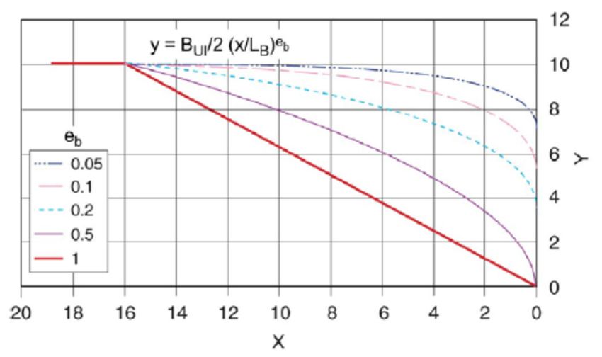
y = BUI / 2·(x/LB)eb, [m], (see Fig. 3.9.2.1-1 and 3.9.2.1-2)
DUI = displacement as defined in 1.2.8 not to be taken less than 10 [kt]
Awp = waterplane area corresponding to the upper ice waterline (UIWL), [m2]
CFF = flexural failure class factor from Table 3.1.2.1
Head 3.9 LONGITUDINAL STRENGTH, Figure 3.9.2.1-1 is changed:
Figure 3.9.2.1-1 Bow shape definition
20216 RULES FOR THE CLASSIFICATION OF SHIPS
PART 29
AMENDMENTS No. 1
Head 3.9 LONGITUDINAL STRENGTH, title of the Figure 3.9.2.1-2 is renamed as
be read as follows:
Figure 3.9.2.1-2 Illustration of eb effect on the bow shape BUI = 20 and Lb = 16
Head 3.9 LONGITUDINAL STRENGTH, Figure 3.9.2.1-2 has been changed:
Figure 3.9.2.1-2 Illustration of eb effect on the bow shape BUI = 20 and Lb = 16
Head 3.9 LONGITUDINAL STRENGTH, item 3.9.3.1 is partly changed and should
be read as follows:
3.9.3.1 The design vertical ice shear force, FI, along the hull girder is to be taken as:
FI = Cf · FIB , [MN]
where:
Cf = longitudinal distribution factor to be taken as follows:
(a) Positive shear force
Cf = 0.0 between the aft end of LUI and 0.6 LUI from aft
Cf = 1.0 between 0.9 LUI from aft and the forward end of LUI
(b) Negative shear force
Cf = 0.0 at the aft end of LUI
Cf = 0.5 between 0.2 LUI and 0.6 LUI from aft
Cf = 0.0 between 0.8 LUI from aft and the forward end of LUI
Intermediate values are to be determined by linear interpolation.
Head 3.9 LONGITUDINAL STRENGTH, item 3.9.4.1 is partly changed and should
be read as follows:
3.9.4.1 The design vertical ice bending moment, MI, along the hull girder is to be taken as:
MI = 0.1 · Cm · LUI · sin-0.2 (γstem) · FIB , [MNm]
where:
LUI = length as defined in 1.2.7, [m]
γstem = as given in 3.9.2.1
FIB = design vertical ice force at the bow, [MN]
Cm = longitudinal distribution factor for design vertical ice bending moment to be taken as follows:
Cm = 0.0 at the aft end of LUI
Cm = 1.0 between 0.5 LUI and 0.7 LUI from aft
Cm = 0.3 at 0.95 LUI from aft
Cm = 0.0 at the forward end of LUI
Intermediate values are to be determined by linear interpolation.
2021RULES FOR THE CLASSIFICATION OF SHIPS 7 PART 29 AMENDMENTS No. 1 Head 3.9 LONGITUDINAL STRENGTH, item 3.9.4.2 is partly changed and should be read as follows: 3.9.4.2 The applied vertical bending stress, σa, is to be determined along the hull girder in a similar manner as in Section 4.6.4.1 of the Rules for the classification of ships, Part 2 - Hull, by substituting the design vertical ice bending moment for the design vertical wave bending moment. The ship still water bending moment is to be taken as the permissible still water bending moment in sagging condition. 2021
You can also read