RUN mXTEND: OPTIMIZE THE ANTENNA OF - APPLICATION NOTE RUN mXTENDTM (NN02-224) - Mouser
←
→
Page content transcription
If your browser does not render page correctly, please read the page content below
RUN mXTEND™:
OPTIMIZE THE
ANTENNA OF
             ®
YOUR mangOH
YELLOW OPEN
PLATFORM

APPLICATION NOTE
RUN mXTENDTM (NN02-224)
APPLICATION NOTE
                                                                    RUN mXTENDTM (NN02-224)

Optimize the antenna of your mangOH® Yellow open
platform
   -    Antenna Component: RUN mXTENDTM NN02-224
   -    Dimensions: 12.0 mm x 3.0 mm x 2.4 mm
   -    Frequency regions: 698-960MHz and 1710-2690MHz

                 Discover how to boost the RF signal on a
                        mangOH® Yellow platform

The RUN mXTEND™ cellular embedded IoT antenna into the mangOH® Yellow is an
example of the new generation of tiny antenna boosters available for multiband
connectivity. Integrating the antenna into the mangOH® Yellow fast prototyping super sensor
ensures a fast and economic development of the new generation of IoT devices.

The miniature chip antenna component is connected to the RF transceiver through a matching
network that shapes the frequency response of the wireless platform. To ensure a fast and
economic development of the new generation of IoT devices, module and chip makers have
created several prototyping kits, developing platforms and reference designs like the mangOH®
Yellow fast prototyping super sensor.

The PCB of a new cellular IoT design based on mangOH® Yellow can be customized according
to customer design needs. Discover within this application note how to boost the RF signal on
the platform. This reference design presents easy and effective ways to modify the PCB in order
to boost the LTE antenna performance embedded in the cellular IoT device based on
mangOH® Yellow.

TABLE OF CONTENTS

Last Update: April 2021                                                                           2
APPLICATION NOTE
                                                 RUN mXTENDTM (NN02-224)

1.      PRODUCT DESCRIPTION mangOH® Yellow & RUN mXTEND™               4

2.      HOW TO BOOST THE RF SIGNAL ON mangOH® Yellow PLATFORM          6

     2.1.   MATCHING NETWORK                                           6

     2.2.   BOOST THE LTE ANTENNA PERFORMANCE                          7

     2.3.   RESULTS AND DESIGN GUIDELINES                             10

Last Update: April 2021                                                    3
APPLICATION NOTE
RUN mXTENDTM (NN02-224)
1. PRODUCT DESCRIPTION mangOH® Yellow & RUN
mXTEND™
The mangOH® Yellow environment delivers all the hardware, software and cloud tools to ensure
that a low power cellular IoT application is developed in a short period of time. The super smart
edge open source solution has a compact form factor (65 mm x 42 mm, smaller than a credit
card) and its open license allows engineers to reproduce the design as needed and prototype
ideas quickly and go to market in weeks, not years. Build low-power IoT devices that can run
for 10+ years.
mangOH® Yellow HIGHLIGHTS
• Snap-in socket to add any CF3©-compatible
modules, including wireless modules (2G to 4G &
LTE-M/NB-IoT)
• Built-in Wi-Fi b/g/n and Bluetooth 5.0 BLE,
Bluetooth Mesh, NFC tag
• Built-in antennas for cellular, GPS, Wi-Fi,
Bluetooth and NFC
• Built-in accelerometer, gyroscope, magnetometer,
pressure, humidity, acoustic mic, air index quality,
temperature, and light sensors
• Battery charger and battery monitor
• Multiple LEDs, buzzer and touch button
• IoT Expansion Card slot to plug in any technology
based on the IoT Expansion Card open standard
• 15 pin IO connector, SD card, 2-way audio
connector
• 3D-printable case designs available
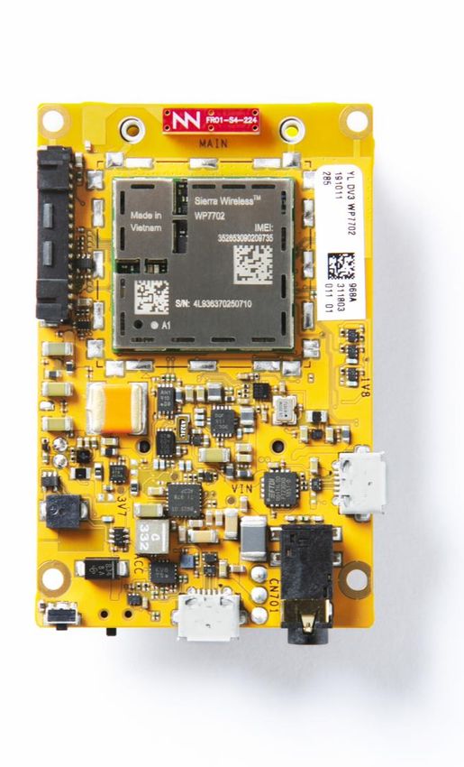
The mangOH® Yellow platform includes a tiny RUN mXTEND™ antenna booster component,
part of the Virtual Antenna™ family by Ignion.
TOP BOTTOM
Material: The RUN mXTENDTM antenna booster is built on glass epoxy substrate.
Last Update: April 2021 4
APPLICATION NOTE
                                                                    RUN mXTENDTM (NN02-224)

The RUN mXTEND™ antenna booster (NN02-224) provides multiband performance in wireless
devices throughout a large range of frequencies (698-8000 MHz) and it is specifically used in
the mangOH® Yellow platform in the range of 698-960 MHz and 1710-2690 MHz. RUN
mXTEND™ enables an IoT platform to feature worldwide coverage allowing operation in
multiple IoT related communication standards such as NB-IoT, LTE-M, LoRa, Zigbee, SigFox,
Neul, Thread, Z-Wave, Weightless, all mobile GSM/UMTS/LTE bands for 2G, 3G, 4G, 5G sub-
6GHz, Bluetooth and Wi-Fi.

                  APPLICATIONS                                   BENEFITS

     •    IoT devices                              •   High efficiency
     •    Modules                                  •   Small size
     •    Routers                                  •   Cost-effective
     •    Handsets and smartphones                 •   Easy-to-use (pick and place)
     •    Tablets                                  •   Off-the-Shelf standard product (no
     •    Digital cameras                              customization is required)
     •    Smartwatches and wearables               •   No clearance beyond footprint.

The RUN mXTENDTM antenna booster belongs to a new generation of antenna solutions based
on the Virtual AntennaTM technology developed by Ignion. The technology is mainly focused on
replacing conventional antenna solutions by miniature, general purpose, and off-the-shelf
components. This breakthrough technology has been specifically designed to fit a diverse set of
wireless applications – IoT devices are just one of the many environments where this tiny
antenna can be transformational.

Last Update: April 2021                                                                           5
APPLICATION NOTE
                                                                    RUN mXTENDTM (NN02-224)

2.     HOW TO BOOST THE RF SIGNAL ON mangOH® Yellow
       PLATFORM

2.1. MATCHING NETWORK
The cellular embedded IoT antenna into the mangOH® Yellow is an example of the new
generation of tiny antenna boosters available for multiband connectivity. The miniature chip
antenna component is connected to the RF transceiver through a matching network that
shapes the frequency response of the wireless platform.

Going from a mangOH® Yellow prototype to a final product does not require changing the
antenna part: the same off-the-shelf component will fit any device with just a little tune of
the matching network. Even the range of frequency bands can be modified with such a little
change. This feature enables a fast development of the final product while making its BoM and
Time-to-Market much more predictable than using old custom solutions.

If a mangOH® Yellow platform is used to design a completely new and different second IoT
device, the antenna component will still be the same. A matching network retuning will make
sure that the same chip antenna component fits the entire range of IoT product portfolio.
In the following chapter is explained how cellular connectivity can be optimized following some
simple recommendations in a platform such as mangOH® Yellow.

Last Update: April 2021                                                                           6
APPLICATION NOTE
RUN mXTENDTM (NN02-224)
2.2. BOOST THE LTE ANTENNA PERFORMANCE
The mangOH® Yellow sensor is an open-source hardware platform (gerbers and schematic are
open to wireless designers), therefore the PCB of a new cellular IoT design based on mangOH®
Yellow can be customized according to customer design needs.
This PCB change can not only meet mechanics criteria for a new device but also be designed
in a way that radioelectric performance is improved. In this sense, this section presents easy
and effective ways to modify the PCB in order to boost the LTE antenna performance
embedded in the cellular IoT device based on mangOH® Yellow. Four changes are proposed
and analyzed here (Figure 1):
1. Removing nearby grounded components.
2. Enlarging the clearance area around the antenna chip component.
3. Extending the size of the PCB.
4. Optimizing the position of the feeding line to the antenna chip component.
As shown in the graphs below, applying one or a combination of these changes can significantly
improve the radiation performance of your mangOH® Yellow, with improvements that range from
1 and up to 10 dB in the low frequency region.
These results can be easily replicated using an electromagnetic CAD to model the main parts
of the device: the antenna booster, the PCB including the ground plane and the substrate (FR4,
1mm thick with r=4.15 and tan=0.014).
To measure the relative improvement of the different design changes, the following figure of
merit is proposed. The total efficiency (t) averaged at 698MHz-960MHz and 1710MHz-
2690MHz is calculated for each scenario (Figure 1). Then, these averaged values are
compared to the original device. The total efficiency t is the fraction of input power that is
radiated to space. This efficiency depend on two factors: the system losses on one side r ,
which include losses due to plastic covers, components on the PCB, matching network and
losses in the antenna booster itself, and the antenna impedance mismatch (S11) on the other
side. Total efficiency is then defined as t=r·(1-|S11|2). For instance, if the power of the LTE
module delivered to the antenna is Pout=23dBm and the total efficiency is t=50% (-3dB), the
output radiated power (also known as total radiated power, TRP) is 23dBm-3dB=20dBm since
TRP(dBm)=Pout(dBm)+10log10(t). Same argument applies to reception as the antenna is a
reciprocal device.
Last Update: April 2021 7APPLICATION NOTE
RUN mXTENDTM (NN02-224)
antenna booster: 12 mm x 3.2 mm x 2.4mm (h)
screw connection screw connection (grounded in the original case)
feeding line
ground clearance
excitation port
ground plane
antenna booster antenna booster antenna booster antenna booster antenna booster
2.8mm 2.8mm 7.8mm 7.8mm 2.8mm
ground clearance ground clearance ground clearance ground clearance ground clearance
34 mm x 6 mm 34 mm x 6 mm 34 mm x 11 mm 34 mm x 11 mm 34 mm x 6 mm
ground plane ground plane ground plane ground plane ground plane
Original situation
42mm 42mm 42mm 42mm 60mm
65 mm 65
65mm
mm 65
65 mm
mm
antenna booster antenna booster antenna booster antenna booster
2.8mm 2.8mm 7.8mm 7.8mm
ground clearance ground clearance ground clearance ground clearance
34 mm x 6 mm 34 mm x 6 mm 34 mm x 11 mm 34 mm x 11 mm
ground plane ground plane ground plane ground plane
42mm 42mm 42mm
65 mm 65 mm 65 mm 65 mm
30mm
60mm 60mm 60mm
Figure 1 - Cases considered in the analysis: screw connectors, change ground clearance,
change feeding location, and change PCB size. Each scenario has a matching network at the
excitation port which comprises lumped elements (capacitors and inductors). Only the original
case has the screw connectors connected to the ground of the PCB; at the other cases, such
screw connectors are floating (non-grounded).
With these considerations, the figure is merit is then defined by eq. (1):
t new PCB
( dB ) = 10 log
t original
(1)
Being t original and t new PCB the average total efficiency in a given frequency range [f1,f2] for the
original device and the new PCB case, respectively. Two frequency ranges are studied: the first
one comprises [f1,f2]=[698MHz-960MHz] covering the low bands of LTE, and the second one
comprises [f1,f2]=[1.71GHz-2.69GHz] covering the high-bands of LTE.
Last Update: April 2021 8APPLICATION NOTE
RUN mXTENDTM (NN02-224)
In this sense, a =3dB increment means that total efficiency is increased by 3dB when compared
to the original device. This figure of merit is useful to determine the impact of each scenario
when doing a new PCB design to get the best of the antenna performance in the device (Figure
2).
For each scenario, the matching network at the excitation port is optimized to maximize total
efficiency with Microwave Office AWR Design tool by Cadence. Such matching networks
comprise lumped inductor and capacitors including losses.
Figure 2 - Impact of the PCB size and ground clearance for the low frequency region (698MHz-
960MHz) and the high frequency region (1710MHz-2690MHz). Original device PCB is 65 mm x
42 mm.
Last Update: April 2021 9APPLICATION NOTE
RUN mXTENDTM (NN02-224)
2.3. RESULTS AND DESIGN GUIDELINES
Results from Figure 2 reveal several interesting design guidelines to be followed when
optimizing the RF performance of a mangOH® Yellow platform:
• Conducting portions close to the antenna should be avoided, but if those cannot be
avoided, those portions should be non-grounded. In this present situation, when the
screw connectors are non-grounded, the performance at the low frequency region is
improved by =1.2dB compared to the original situation where the screw connectors are
grounded. From now on, all the remaining cases have non-grounded screw connectors.
• Increasing ground clearance while maintaining the PCB size (see legend at Figure 2)
can increase performance =3.7dB both at the low and =1.8dB at the high frequency
region. This ground clearance increment is due to a larger gap of the antenna booster to
the ground plane. For this case, the gap between the antenna booster is increased from
2.8mm to 7.8mm.
• Increasing ground clearance while maintaining the PBC size and moving the feeding line
to the corner, provides further improvement at the low frequency range of =5.5dB.
• PCB width has also a positive effect, although slightly for the case under test. This
increment, however, is not as significant as the ones obtained by increasing the ground
clearance.
• Increasing PCB length has a positive impact in the 698-960MHz region whereas in the
1710MHz-2690MHz is almost the same. When increasing the ground plane for the
original PCB size by 30 mm, the improvement at the low frequency region is 4.7dB and
7.8dB when enlarging 60mm.
• When combining the increase of ground clearance and PCB size, the performance is
improved =8.7dB and =1.9dB at the low and high frequency regions, respectively.
• Finally, when combining the increase of ground clearance, PCB length, and antenna
booster feeding line at the corner of the PCB, the positive effects are added, that is,
performance is improved at both frequency regions, in particular =10.5dB at the low
frequency region and =1.8dB at the high frequency region.
These are useful design recommendations for optimizing performance at the conception
phase of an IoT project when the designer has still freedom to modify the PCB size. These
design rules should be made at the very beginning of a design project. This will minimize and
even avoid cumbersome PCB modifications while the project is in the development phase when
all electronics, chipsets, and mechanics are already fixed. Therefore, it is recommended
always to think first about these design lines when designing a cellular IoT device based
on mangOH® Yellow to get the best of it.
Last Update: April 2021 10APPLICATION NOTE
RUN mXTENDTM (NN02-224)
Once the PCB size is fixed, embedding a Virtual Antenna™ in an IoT device follows a simple
design flow consisting of three simple steps: 1) placing the antenna booster in the PCB; 2)
designing the matching network for your PCB size; 3) testing and fine tuning the real
device, which makes the whole embedded antenna design process much faster, cheaper and
easier than the traditional choice of developing a custom antenna.
If you need assistance to design your matching network, please contact support@ignion.io, or
try our free-of-charge1 NN Wireless Fast-Track design service, you will get your chip antenna
design including a custom matching network for your device in 24h1. Other related to NN’s range
of R&D services is available at: https://www.ignion.io/rdservices/
1
See terms and conditions for a free NN Wireless Fast-Track service in 24h at: https://www.ignion.io/fast-track-project/
Last Update: April 2021 11APPLICATION NOTE
RUN mXTENDTM (NN02-224)
Ignion products are protected by Ignion patents.
All information contained within this document is property of Ignion and is subject to change
without prior notice. Information is provided “as is” and without warranties. It is prohibited to copy
or reproduce this information without prior approval.
Ignion is an ISO 9001:2015 certified company. All our antennas are lead-free and RoHS
compliant.
ISO 9001: 2015 Certified
Last Update: April 2021 12APPLICATION NOTE
RUN mXTENDTM (NN02-224)
Contact:
support@ignion.io
+34 935 660 710
Barcelona
Av. Alcalde Barnils, 64-68 Modul C, 3a pl.
Sant Cugat del Vallés
08174 Barcelona
Spain
Shanghai
Shanghai Bund Centre
18/F Bund Centre, 222 Yan’an Road East,
Huangpu District
Shanghai, 200002
China
New Dehli
New Delhi, Red Fort Capital Parsvnath Towers
Bhai Veer Singh Marg, Gole Market,
New Delhi, 110001
India
Tampa
8875 Hidden River Parkway
Suite 300
Tampa, FL 33637
USA
Last Update: April 2021 13You can also read