SCKB, SCKB-CARS Supercontinuum Kit User Guide
←
→
Page content transcription
If your browser does not render page correctly, please read the page content below
SCKB, SCKB-CARS
Supercontinuum Kit

User Guide

Rev A, September 8, 2011
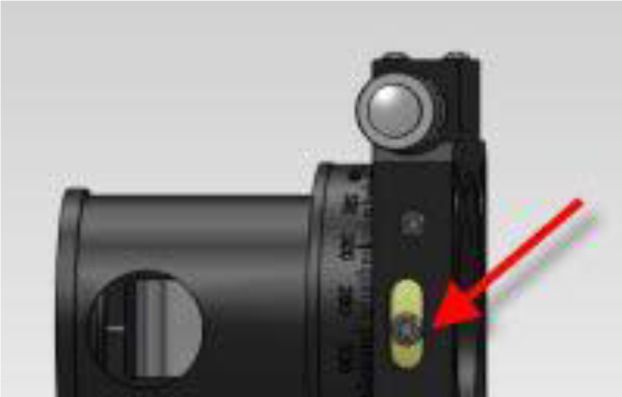
Table of Contents
Chapter 1     Warning Symbol Definitions............................................................................................. 3
Chapter 2     Safety................................................................................................................................... 4
Chapter 3     Introduction ........................................................................................................................ 5
Chapter 4     Setup Description .............................................................................................................. 6
Chapter 5     Initial Setup and Alignment .............................................................................................. 7
       5.1. Aligning the Input Periscope Assembly ...................................................................... 7
       5.2. Installing the Optical Isolator ....................................................................................... 7
       5.3. Installing the Folding Mirror Pair ................................................................................. 8
       5.4. Installing the Optical Attenuator .................................................................................. 8
       5.5. Installing the Flexure Stages ....................................................................................... 9
       5.6. Installing the Photonic Crystal Fiber Module ........................................................... 10
       5.7. Installing the Coupling Objectives ............................................................................ 10
       5.8. Coupling Light into the PCF Module ......................................................................... 10
Chapter 6     Additional Accessories ................................................................................................... 12
Chapter 7     Key Features and Specifications ................................................................................... 13
       7.1. Features ...................................................................................................................... 13
       7.2. Specifications ............................................................................................................. 13
Chapter 8     Sample Spectra ................................................................................................................ 14
       8.1. SCKB (SCKB/M) .......................................................................................................... 14
       8.2. SCKB-CARS (SCKB-CARS/M).................................................................................... 14
Chapter 9     Regulatory ........................................................................................................................ 15
       9.1. Waste Treatment is Your Own Responsibility .......................................................... 15
       9.2. Ecological Background .............................................................................................. 15
Chapter 10    Thorlabs Worldwide Contacts ........................................................................................ 16
Supercontinuum Kit Chapter 1: Warning Symbol Definitions
Chapter 1 Warning Symbol Definitions
Below is a list of warning symbols you may encounter in this manual or on your device.
Symbol Description
Direct Current
Alternating Current
Both Direct and Alternating Current
Earth Ground Terminal
Protective Conductor Terminal
Frame or Chassis Terminal
Equipotentiality
On (Supply)
Off (Supply)
In Position of a Bi-Stable Push Control
Out Position of a Bi-Stable Push Control
Caution: Risk of Electric Shock
Caution: Hot Surface
Caution: Risk of Danger
Warning: Laser Radiation
Caution: Spinning Blades May Cause Harm
Rev A, September 8, 2011 Page 3Supercontinuum Kit Chapter 2: Safety
Chapter 2 Safety
All statements regarding safety of operation and technical data in this instruction manual will only apply when the
unit is operated correctly.
! WARNING !
This unit must not be operated in explosive environments.
! WARNING !
Latex gloves should be worn to prevent oil from fingers from reaching all optical surfaces. Make
sure you use appropriate laser safety glasses during setup and operation.
WARNING
Avoid Exposure—ASE and laser radiation emitted from apertures.
Never look directly into beam.
Rev A, September 8, 2011 Page 4Supercontinuum Kit Chapter 3: Introduction Chapter 3 Introduction First observations of supercontinuum generation date back as far as the 1970s in bulk materials and optical fibers. However, these early experiments required very high energy pulses. The advent of photonic crystal fibers (PCF) have made supercontinuum generation much more accessible – the small mode field diameter in PCFs lead to large power densities in the fiber, and the possibility to engineer dispersion in PCFs allows matching of a fiber’s zero dispersion wavelength to the range accessible by commonly used Titanium-Sapphire femtosecond oscillators. Since then, supercontinua have found a multitude of applications in metrology, microscopy and spectroscopy. The Thorlabs SCKB contains all necessary equipment to conveniently set up supercontinuum generation using a femtosecond Titanium-Sapphire pump source (The SCKB contains imperial components, whereas the SCKB/M contains their metric counterparts). The SCKB-CARS ships with a different PCF module, which has two zero dispersion wavelengths and is suitable for Coherent Anti-Stokes Raman Scattering (CARS) microscopy. Rev A, September 8, 2011 Page 5
Supercontinuum Kit Chapter 4: Setup Description
Chapter 4 Setup Description
The Thorlabs Supercontinuum Kit contains all the necessary optics and optomechanics to couple light from a
Titanium-Sapphire pump source into a PCF module and to collimate the supercontinuum generated at the fiber
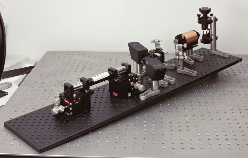
output facet. Figure 1 shows an overview of the assembled system.
1. The periscope assembly (RS99) at the input side of the assembly allows the beam height of your pump
source to be matched to the height of the optical axis in the SCKB (85mm).
2. A broad-band optical isolator (IO-5BB-840-LP-CL1) eliminates back-reflections from the fiber facet into
the pump source, which can otherwise disrupt the mode-locking of your Titanium-Sapphire laser.
3. A pair of folding mirrors in ultra-stable mirror mounts (POLARIS-K1) is used to precisely align the beam to
the fiber assembly and input optics.
4. An achromatic half-wave plate (AHWP05M-980) is mounted in a precision rotation mount. Together with a
laser grade calcite polarizer (GL10-B), this can be used to set the input power to the PCF module with
high accuracy. Two BT610 beam traps are in place to safely dump the light rejected by the polarizer.
5. A microscope objective (RMS40X) is mounted to an MBT616 three-axis flexure stage. The MBT616’s
differential adjusters facilitate coupling into the PCF module. Coupling efficiency in excess of 60% can be
achieved.
6. The PCF module is mounted fixed between the two MBT616 stages that hold the input and output
coupling objectives.
7. A second MBT616 flexure stage holds an RMS20X microscope objective, which is used to collect and
collimate the supercontinuum light generated in the PCF module.
Figure 1 Model of the Thorlabs Supercontinuum Generation Kit. The red arrow indicates the
incoming pulse, while the blue arrow indicates the output light.
Rev A, September 8, 2011 Page 6Supercontinuum Kit Chapter 5: Initial Setup and Alignment
Chapter 5 Initial Setup and Alignment
Unless otherwise noted, all of the parts mentioned in this section are included.
WARNING
Please observe proper laser safety procedures. IR laser beams are particularly dangerous because
they cannot be seen. Always wear the appropriate type of laser glasses (not included) when working
with laser beams.
The supercontinuum light generated in the PCF module should be treated with particular care, as
the nature of the broad continuum does not allow laser safety goggles to provide effective
protection.
The following contains step-by-step instructions to setup and align the Thorlabs Supercontinuum Generation kit. If
you have questions regarding the instructions, please contact our technical support department
(techsupport@thorlabs.com).
Throughout the text, Thorlabs part numbers are set in italics. The instructions refer to imperial components, with
their metric counterparts added in brackets.
5.1. Aligning the Input Periscope Assembly
• Mount two of the included BB1-E03 mirrors in the holders of the RS99 (RS99/M) periscope assembly.
• Ensure that the pedestal adapter BE1 (BE1/M) is screwed tightly into the RS99’s post, and then mount
the RS99 assembly to your optical table using the included CF125 clamp.
• Adjust the height of the input mirror so that your pump beam hits the mirror at the center.
• Now adjust the height of the output mirror assembly, such that the outgoing beam is at the height of the
optical axis of the SCKB, 85 mm (approximately 3 1/3”) above the breadboard. Small deviations from the
optical axis height can be corrected with the folding mirror pair, so it is not crucial to be very precise in this
step.
• Use the kinematic adjusters on the input mirror to ensure that the output beam is parallel to the surface of
the optical table.
• Finally, tighten the setscrews to lock the rotational degrees of freedom of the RS99 assembly.
5.2. Installing the Optical Isolator
• Mount the IO-5BB-840-LP-CL1 isolator on two RS1.5P8E (RS1.5P4M) posts, using RS02 spacers
between the posts and the isolator mount. The isolator mount contains both metric and imperial mounting
holes, which are clearly labeled.
• Install the isolator in the beam path, close to the periscope assembly. The input side of the isolator is
labeled. Ensure that you get good transmission across the isolator (>85%). If you cannot achieve good
transmission or notice artifacts on your output beam, realign the periscope assembly.
• It is useful to be able to measure the transmitted power through the isolator. It is therefore recommended
to leave sufficient space between isolator and the folding mirror pair (see section 5.3) to accommodate a
power measurement head.
Rev A, September 8, 2011 Page 7Supercontinuum Kit Chapter 5: Initial Setup and Alignment
5.3. Installing the Folding Mirror Pair
• Install the remaining two BB1-E03 dielectric mirrors into the POLARIS-K1 ultra-stable mirror mounts. Do
not over tighten the leaf spring assembly that holds the mirrors in place.
• Mount the POLARIS-K1 onto the RS2P8E (RS2P4M) pedestal post, using a RS02 spacer in between
post and mirror mount.
• Position the first mirror in the beam path, tilted 45 degrees from the incident beam, and secure it to the
breadboard using a CL125 clamp. The second mirror should be roughly positioned so that the outgoing
beam is propagating between two rows of holes on the optical table. Again, secure this assembly using a
CL125 clamp.
5.4. Installing the Optical Attenuator
• Mount the two CRM1 (CRM1P/M) and CRM1P (CRM1P/M) rotation mounts on top of RS2P8E (RS2P4M)
posts, using RS03 spacers in between. Two ¾" long 8-32 (20 mm long M4) setscrews are included for
this assembly.
• Mount the achromatic half wave plate AHWP05M-980 into the CRM1P, and secure it using a SM1RR
retaining ring (included with the rotation mount). A SPW602 spanner wrench is included to facilitate the
tightening of the retaining ring.
• Next, after reading and following the precautions on the packaging for the GL10-B polarizer, mount it
inside the SM1PM10 polarizer mount. The SM1PM10 offers a setscrew to secure the polarizer in place.
Please note that the rejected beams do not exit the polarizer at a 90 degree angle; it is normal for the
SM1PM10 exit windows to not line up with the output windows of the polarizer.
• Place the wave plate and the polarizer in the beam path, and secure the pedestal post using CF125
clamps. By rotating the wave plate, you can now set the amount of optical power transmitted through the
polarizer. For coarse alignment, the setscrew on the CRM1P can be loosened, and the mount can be
rotated by hand. Fine alignment using the micrometer can be performed after tightening the setscrew
(See Figure 2).
CAUTION
! !
Do not attempt to coarsely rotate the mount while the micrometer is engaged.
Figure 2 The red arrow shows the setscrew that engages the micrometer. Note that the SM1P10
window does not overlap with the polarizer exit window.
Rev A, September 8, 2011 Page 8Supercontinuum Kit Chapter 5: Initial Setup and Alignment
• Depending on the output power of your femtosecond oscillator, and the desired input power for the PCF
module, there may be several Watts of optical power emitted from the exit apertures of the polarizer. To
safely dump this excess light, two BT610 (BT610/M) beam traps are included. Mount the BT610s on
RS2P8E (RS2P4M) posts, with RS02 spacers in between. Position the assemblies under a slight angle
near the output apertures of the SM1PM10, so that the rejected light enters the beam traps, and clamp
them down using CF125 clamps.
WARNING
Never operate the SCKB without the beam traps in place.
5.5. Installing the Flexure Stages
• Install the AMA007 (AMA007/M) angle brackets on the MBT616 (MBT616/M) stages. Roughly center the
stages, so that the alignment notch on the stage and the angle bracket are aligned.
• Mount two SM1D12D iris diaphragms in the HCS031 mounts, and install them on the opposing ends of
the AMA007 bracket and the MBT616 stage, as shown in Figure 3. Secure the HCS031 using the cleats
and screws included with them.
Figure 3 Iris diaphragms mounted on the MBT616 stage.
• Place the MBT616 stage on the optical table so that the alignment notch is along the beam path and that
there is enough space between the stage and the polarizer assembly to accommodate a power sensor.
Use ¼"-20 (M6) cap screws to attach the stage to the breadboard.
• Use the pair of folding mirrors to align the beam through both irises. The easiest way to do so is to close
the first iris, then use the first mirror to align the beam through the diaphragm. Then open the first iris and
use the second mirror to align the beam to the second iris. Iterate these steps until the beam passes both
iris diaphragms simultaneously.
Rev A, September 8, 2011 Page 9Supercontinuum Kit Chapter 5: Initial Setup and Alignment
• Mount the second flexure stage so that the AMA007 brackets are facing each other, and so that there are
four mounting holes visible in between the stages in the rows aligned with the beam. Place one of the
HCS031 holding an iris onto the AMA007 and move the stage so that the beam passes through the iris.
This alignment is not critical and does not have to be performed rigorously.
5.6. Installing the Photonic Crystal Fiber Module
• Place the two SCKB-HCS031 mounts on the AMA007 brackets. Remove the protective caps from the
PCF module and slide the module into the SCKB-HCS031 holders. Affix the SCKB-HCS031s to the
brackets using the included cleats and cap screws, so that the end facets of the PCF module are close to
the end face of the SCKB-HCS031.
• Use an SM1RR retaining ring on each side of the PCF module to secure it in place. Rotate the PCF
module, so that the inscribed polarization axis is parallel to the polarizer’s. Now gently tighten the
setscrews on top of the SCKB-HCS031.
5.7. Installing the Coupling Objectives
• Remove the iris diaphragms from the HCS031 mounts.
• Mount the SM1A3 adapters in the HCS031, so that they are flush with one of the HCS031’s surfaces.
Install a SM1RR retaining ring from the back, so that the SM1A3 adapter is held in place – again, the
SPW602 spanner wrench will facilitate the tightening of the retaining ring.
• Install the two objectives in the SM1A3 adapters, and mount the HCS031 on the MBT616 stages using
the included cleats and screws. The 40X objective will give about 60% coupling efficiency into the fiber
module, while the 20X objective has around 30% coupling efficiency, when using a Coherent Chameleon
laser. Depending on your laser’s output mode quality and beam diameter, these values will vary. It is
slightly easier to use the 20X objective for coupling, and will be less susceptible to misalignment. If you do
not have much experience coupling light into PCF or single mode fiber, we recommend you use the 20X
objective for your first attempts of coupling into the fiber, and the 40X objective to collimate the fiber
output. The table below gives the working distances as a rough guide to the distance needed between the
objective and the PCF module end facet.
Objective Working Distance
RMS20X 1.2 mm (~3/64")
RMS40X 0.6 mm (~3/128")
5.8. Coupling Light into the PCF Module
You are now ready to couple light into the photonic crystal fiber. Set up your laser to operate at 800nm. Use the
wave plate to set the laser power to less than 50mW.
WARNING
Performing the coarse alignment at higher powers will damage the PCF module. Always ensure you
are working at low power when performing the fiber alignment.
• Align the focus of the input coupling objective with the front facet of the PCF module using the MBT616
stage x-adjuster (coaxial to the beam path). Light reflected from the end facet can be observed at the exit
port of the polarizer. If this reflected beam is collimated, the focus is roughly aligned.
• Use the y- and z-adjusters (normal to the beam path) to couple light into the fiber. Initially, an
unstructured spot will be observed at the output. This spot will gain a circular structure as the coupling
efficiency increases. Eventually, the central spot will be completely eliminated.
Rev A, September 8, 2011 Page 10Supercontinuum Kit Chapter 5: Initial Setup and Alignment
• Iterate between using the y- and z- adjusters of the MBT616 stage and the folding mirror pairs to achieve
optimum coupling. Now gradually increase the input power, until visible light can be observed at the exit
aperture.
WARNING
Never exceed 1 W of power at the input aperture of the PCF module.
Rev A, September 8, 2011 Page 11Supercontinuum Kit Chapter 6: Additional Accessories
Chapter 6 Additional Accessories
The following parts will be helpful to set up and operate the SCKB, but are not included.
• Power meter PM100A with a fast, low power head (e.g., S130C) to help with fiber coupling, and a slow,
high-power thermal head to measure input power settings (e.g., S310C).
• Appropriate laser goggles, like the LG9 to block the Ti:Sapphire output light.
WARNING
Note that due to the spectrally broad nature of the supercontinuum, goggles cannot offer protection
against the output of the SCKB! We recommend enclosing the supercontinuum beam once it is set
up for your application. Thorlabs offers an extensive array of lens tubes and accessories to enclose
beams.
• Transmission grating GT25-08 to disperse the supercontinuum into its spectral components (See Figure
4).
Figure 4 Example output of the SCKB dispersed using a GT25-08 transmission Grating
Rev A, September 8, 2011 Page 12Supercontinuum Kit Chapter 7: Key Features and Specifications
Chapter 7 Key Features and Specifications
7.1. Features
• Two, 3-Axis Flexure Stages with Differential Micrometers
• Broadband Optical Isolator
o 750 nm - 950 nm
o >33 dB Isolation
o >88% Transmission
• Olympus Plan Achromatic Objectives
o 20X, NA = 0.4, WD = 1.2 mm
o 40X, NA = 0.65, WD = 0.6 mm
• Laser-Grade Calcite Glan-Taylor Polarizer
• Air-Gapped Achromatic Half Wave Plate
7.2. Specifications
• Optical Axis Height: 85 mm
• Up to 1 W Input Power
• >60% Coupling Efficiency (Coherent Chameleon Pump Source, Efficiency will Vary by Source)
Rev A, September 8, 2011 Page 13Supercontinuum Kit Chapter 8: Sample Spectra Chapter 8 Sample Spectra 8.1. SCKB (SCKB/M) Sample output spectra for the standard PCF module. Laser parameters are given in the tables above each plot. Central Wavelength 780 nm Central Wavelength 780 nm Repetition Rate 100 MHz Repetition Rate 250 MHz Pulse Duration 60 fs Pulse Duration
Supercontinuum Kit                                                                             Chapter 9: Regulatory

Chapter 9              Regulatory
As required by the WEEE (Waste Electrical and Electronic Equipment Directive) of the European Community and
the corresponding national laws, Thorlabs offers all end users in the EC the possibility to return “end of life” units
without incurring disposal charges.

    •   This offer is valid for Thorlabs electrical and electronic equipment:
    •   Sold after August 13, 2005
    •   Marked correspondingly with the crossed out “wheelie bin” logo (see right)
    •   Sold to a company or institute within the EC
    •   Currently owned by a company or institute within the EC
    •   Still complete, not disassembled and not contaminated
                                                                                              Wheelie Bin Logo
As the WEEE directive applies to self-contained operational electrical and electronic products, this end of life take
back service does not refer to other Thorlabs products, such as:

    •   Pure OEM products, that means assemblies to be built into a unit by the user (e. g. OEM laser driver
        cards)
    •   Components
    •   Mechanics and optics
    •   Left over parts of units disassembled by the user (PCB’s, housings etc.).

If you wish to return a Thorlabs unit for waste recovery, please contact Thorlabs or your nearest dealer for further
information.

9.1.    Waste Treatment is Your Own Responsibility
If you do not return an “end of life” unit to Thorlabs, you must hand it to a company specialized in waste recovery.
Do not dispose of the unit in a litter bin or at a public waste disposal site.

9.2.    Ecological Background
It is well known that WEEE pollutes the environment by releasing toxic products during decomposition. The aim of
the European RoHS directive is to reduce the content of toxic substances in electronic products in the future.

The intent of the WEEE directive is to enforce the recycling of WEEE. A controlled recycling of end of life products
will thereby avoid negative impacts on the environment.

Rev A, September 8, 2011                                                                                     Page 15
Supercontinuum Kit Chapter 10: Thorlabs Worldwide Contacts
Chapter 10 Thorlabs Worldwide Contacts
USA, Canada, and South America
Thorlabs, Inc.
56 Sparta Avenue
Newton, NJ 07860
USA
Tel: 973-579-7227
Fax: 973-300-3600
www.thorlabs.com
www.thorlabs.us (West Coast)
Email: sales@thorlabs.com
Support: techsupport@thorlabs.com
Europe UK and Ireland
Thorlabs GmbH Thorlabs Ltd.
Hans-Böckler-Str. 6 1 Saint Thomas Place, Ely
85221 Dachau Cambridgeshire CB7 4EX
Germany Great Britain
Tel: +49-(0)8131-5956-0 Tel: +44 (0)1353-654440
Fax: +49-(0)8131-5956-99 Fax: +44 (0)1353-654444
www.thorlabs.de www.thorlabs.com
Email: europe@thorlabs.com Email: sales.uk@thorlabs.com
Support: techsupport.uk@thorlabs.com
France Scandinavia
Thorlabs SAS Thorlabs Sweden AB
109, rue des Côtes Mölndalsvägen 3
78600 Maisons-Laffitte 412 63 Göteborg
France Sweden
Tel: +33 (0) 970 444 844 Tel: +46-31-733-30-00
Fax: +33 (0) 825 744 800 Fax: +46-31-703-40-45
www.thorlabs.com www.thorlabs.com
Email: sales.fr@thorlabs.com Email: scandinavia@thorlabs.com
Japan China
Thorlabs Japan, Inc. Thorlabs China
Higashi-Ikebukuro Q Building, 1F Room A101, No. 100
2-23-2, Higashi-Ikebukuro, Lane 2891, South Qilianshan Road
Toshima-ku, Tokyo 170-0013 Putuo District
Japan Shanghai
Tel: +81-3-5979-8889 China
Fax: +81-3-5979-7285 Tel: +86 (0)21-32513486
www.thorlabs.jp Fax: +86 (0)21-32513480
Email: sales@thorlabs.jp www.thorlabs.hk
Email: chinasales@thorlabs.com
Rev A, September 8, 2011 Page 16www.thorlabs.com
You can also read