SOUNDWAVE 2.2 Quick Reference Guide - FAST, EFFICIENT, INNOVATIVE
←
→
Page content transcription
If your browser does not render page correctly, please read the page content below

FAST, EFFICIENT, INNOVATIVE

SOUNDWAVE™ 2.2
   Quick Reference Guide
Improve Your Workflow, Enhance Your Productivity

SOUNDWAVE™ 2.2
                                                                                                   Quick Reference Guide

Contents
  1 Programming Guidelines...................................................................................................................................... 2
 2 Naída CI Q70 Sound Processor........................................................................................................................ 9
 3 HiRes™ Optima Sound Processing...............................................................................................................20
 4 Neptune™ Programming Guidelines...........................................................................................................23
 5 Bilateral Recipient Management...................................................................................................................28
 6 Clinical Programming Tools..............................................................................................................................33
 7 CPI-3 Programming Device.............................................................................................................................38
 8 NRI Steps and Procedures.................................................................................................................................40
 9 NRI Troubleshooting.............................................................................................................................................44
10		Performing OR Measurements.......................................................................................................................46
SOUNDWAVE™ 2.2
                   Quick Reference Guide

Programming Guidelines
New Patients and Returning Patients
SOUNDWAVE™ 2.2
                                         Quick Reference Guide

Get Started

Launching SoundWave™ Professional Suite version 2.2 (SoundWave 2.2) will generate the Patient Management
window. This is where the list of recipients is found, as well as the fitting hardware tasks group(s).

                                                                                       Fitting Hardware

   Software Options

              Action Pane

                                                                   Preview Pane                           Management Grid

Connect the sound processor to the fitting hardware and place the headpiece on the recipient.
  •   Check the Fitting Hardware Task Group in the Ribbon Bar.
  • The   task group should indicate the implant is ready.

                                                                                  TIP: Click on an icon in the Fitting Hardware task
                                                                                  group to access hardware options. For example, click
                                                                                  on the sound processor to initialize or backup the
                                                                                  sound processor.

3 Programming Guidelines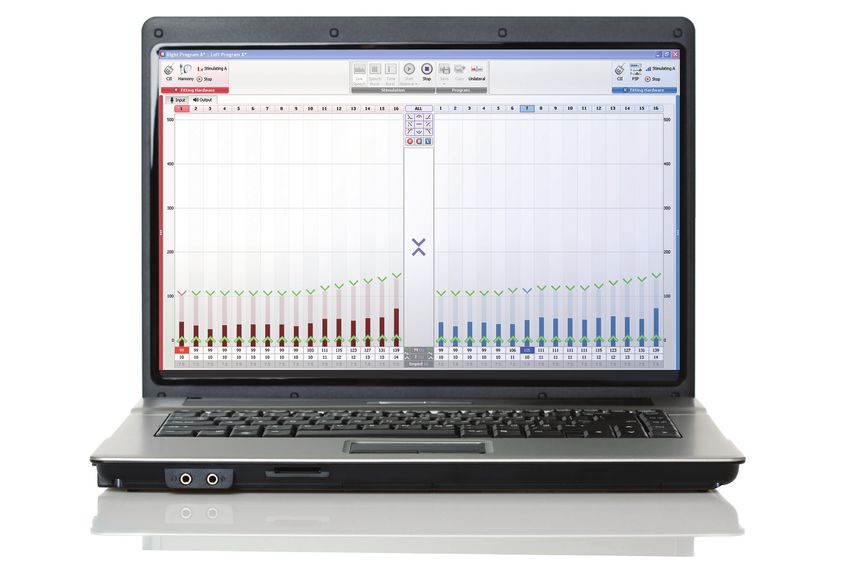
SOUNDWAVE™ 2.2
                                               Quick Reference Guide

   Programming Steps: New Patient

   Step 1: Create the Patient File
   • Select    New in the Action Pane, enter the required information, and select OK.
   • The   New Implant Window will open. Enter the required information and select OK.

     Note that the New Implant Window will also appear when placing the headpiece on the recipient.

   Step 2: Condition Electrodes
   • Select    the Impedances Tab and then click on Condition Right or Condition Left in the Action Pane. Alternatively,
     select to Run Conditioning from the implant icon in the Fitting Hardware Task Group.

      Impedances run by default when communication is established between the recipient file and the implant, and
      following Conditioning.

   Step 3: Create Programs
   • Go   to the Programs Tab and select New Right, New Left, or New Bilateral in the Action Pane.

   Example: Program Window
   • New      in SoundWave 2.2 is the ability to display the fitting windows as tabs.
                                                                                             Program Parameter Groups

Shaping Tools

Global Tool

Auto T                                                                                                             Frequency
                                                                                                                   Allocation

   4 Programming Guidelines
SOUNDWAVE™ 2.2
                                              Quick Reference Guide

  • Select     a Strategy (HiRes – P is the default).
  • Verify    Audio Mixing in Settings.
          • For   the Harmony sound processor, consider the following and refer to the SoundWave manual for detailed
		 information on Audio Mixing:
		• T-Mic™                     only program: Select Aux Only.
			                  • FM   or External Aux input program: Select 50/50 or 30/70 Mic/Aux.
          • For   the Neptune sound processor, consider the following and refer to the SoundWave manual for detailed
		 information on Audio Mixing:
		• T-Mic                     only program (requires T-Comm™ accessory): Select Mic Only.
		• FM                      or External Aux input program: Select 50/50 or 30/70 Mic/Aux.
          • For the Naída CI Q70 (Naída CI) sound processor, note that Aux refers to the T-Coil, rather than the T-Mic or
		 External Aux. Thus, consider the following:
		• T-Coil                    program: 50/50 or 30/70 Mic/Aux.
		• Refer to the Naída CI Section of this document for information on selecting audio mixing and Mic sources.
  • Volume        /Sensitivity dial setting
		        • Naída    CI, Harmony™, PSP, Auria™, CII BTE and PBTE™ sound processors

                                                                              During programming, if the sound processor has a
                                                                              Volume or Sensitivity dial, this read out will reflect
                                                                              the dial setting.

		        • Neptune     sound processor

                                                                              Neptune Volume and Sensitivity dials are on
                                                                              the Neptune Connect, which is removed during
                                                                              programming. Therefore, these dial settings are
                                                                              managed in the Ribbon Bar.

  In all cases, the read out in the Ribbon Bar is an absolute value between -100 and +100% independent of the
  program Volume and Sensitivity settings.

• Set   M levels with Speech Burst™ or Live Speech stimulation (Speech Burst is the default).
• Fine   tune the settings, for example: increase the Input Dynamic Range from 60 dB to 80 dB to improve access to
 softer sounds or manage Gains from the Input Tab.
• Save   the Program
		        •   Select Save and Close from the Program task group. The program will be assigned an ID in the Patient
			 Management Window.

5 Programming Guidelines
SOUNDWAVE™ 2.2
                                             Quick Reference Guide

    • Create    additional programs. Highlight a program and select Copy from the Action Pane or follow the previous
		 steps for a new program.

        Remember: A program remains editable until loaded to a sound processor, a report is generated, stimulated on
        within the Patient Record Window, or the patient file is closed.

Step 4: Initialize Processor
•   Initialize to prepare the sound processor for programming or to download programs.
    • Select Initialize   from the Processor Pane or the Fitting Hardware Task Group.
    • Enter   the serial number if it is not already populated (optional).
    • Select   side from the drop-down menu to assign processor for Left, Right, or Bilateral use.

        Note that when initialized as a bilateral processor, the processor can be used for either the Right or Left side.

    •   Select Yes.

Step 5: Download Programs
    •   Initialize the sound processor as required.
    •   Click and drag or type the program ID into the desired program slot in the Processor Pane.
    •   Manage LEDs and/or alarms on either a program-by-program basis or a processor-by-processor basis as
			 available for the sound processor connected. Simply click on the status LED, audible alarm or internal alarm
			 icons in the Processor Pane to turn them off.
    •   Click Download in the Processor Pane.

		 Programs can be downloaded to a back-up sound processor by using the Visit History tab: click, drag, and drop a
		 Visit History record onto the Processor Pane. Click Download.

6 Programming Guidelines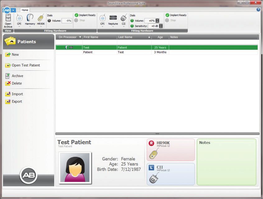
SOUNDWAVE™ 2.2
                                             Quick Reference Guide

Programming Steps: Returning Patient

Step 1: Open the Patient File
    •   Select the recipient name from the Patient Management Grid.

        If this is a transfer recipient, the recipient name may be listed in the Action Pane if the headpiece is attached to the
        recipient’s head.

    •   Double click on the name or choose Open from the Action Pane.

Step 2: Review Impedances
    •   Impedances will run automatically by default when the patient file is opened and communication (lock) is
		 established with the implant.

Step 3: Manage Programs
    •   Select a program from the Patient Record Window and Copy or Open. Alternatively, select New and create a
		 new program.
    •   Manage settings. Consider the following and refer to the SoundWave™ manual for detailed information on
		 strategy, settings, and program management:
           •   Audio Mixing
               See Verify Audio Mixing in Settings in the Programming Steps
			 •          Volume Range
               Disable volume control by setting to the volume range to +/-0%
			 •          Sensitivity
               Create environmental-specific programs by modifying this up to -/+ 10 dB
			 •          Internal Telecoil (Harmony™ and Naída CI sound processors)
               Enable with appropriate Audio Mixing to provide access to Telecoil compatible auxiliary input
			 •          Input Dynamic Range
               Expand to provide access to softer-level sounds and enhance music listening
•   Save the Program
    •   Select Save and Close from the Program task group. The program will be assigned an ID in the Patient
		 Management Window.
    •   Create additional programs. Highlight a program and select Copy from the Action Pane or follow the previous
		 steps for a new program.

7 Programming Guidelines
SOUNDWAVE™ 2.2
                                          Quick Reference Guide

      Remember: A program remains editable until loaded to a sound processor, a report is generated, stimulated within
      the Patient Record Window, or the recipient file is closed.

Step 4: Download Programs
  •   Initialize the sound processor as required.
  •   Click and drag or type the program ID into the desired program slot in the Processor Pane.
  •   Manage LEDs and/or alarms on either a program-by-program basis or a processor-by-processor basis as
		 available for the sound processor connected. Simply click on the status LED, audible alarm or internal alarm
		 icons in the Processor Pane to turn them off.
  •   Click Download in the Processor Pane.

      Programs can be downloaded to a back-up sound processor by using the Visit History tab: click, drag, and drop a
      Visit History record onto the Processor Pane. Click Download.

                                                      Note that when you plug in a Harmony, Neptune or PSP processor you
                                                      will see an Upgrade button in the Processor Pane. This will upgrade new
                                                      firmware to these processors. It will not change any of the programs nor
                                                      their attributes. Once the upgrade is complete, it is recommended that
                                                      they not be plugged into an earlier version of SoundWave as to make them
                                                      work they will need to be initialized.

8 Programming Guidelines
SOUNDWAVE™ 2.2
Quick Reference Guide
Naída CI Sound ProcessorSOUNDWAVE™ 2.2
Quick Reference Guide
The new Naída CI Q70 (Naída CI) sound processor brings advanced Phonak innovations to cochlear implant
recipients, including exclusive Binaural VoiceStream Technology™ from Phonak which leads the industry in wireless
connectivity. The Naída CI sound processor delivers another market first as the only CI sound processor to wirelessly
stream music, phone calls, TV shows, and endless other media.
While there will be some programming and fitting similarities between the Naída CI and other sound processors,
there will also be many distinctive differences described here.
Fitting Hardware
The Naída CI sound processor connects to the CPI-3 (not compatible with CPI-2) using the new Naída CI
programming cable.
Programming the Naída CI Q70 Sound Processor
This image shows the Naída CI sound processor fitting window
UltraZoom
10 Naída CI Sound ProcessorSOUNDWAVE™ 2.2
Quick Reference Guide
There is a new Settings drop down called Mic Mode. The options are Omni Directional and UltraZoom.
Omni Directional is the default Mic Mode, most useful for everyday environments. UltraZoom utilizes the dual
microphone system and incorporates a spatial noise cancellation algorithm designed specifically for directional
applications, such as when in noise.
In addition, there are new features added to the Naída CI sound processor drop down in the Ribbon Bar.
Selecting the Mic Source in the ribbon bar allows the ability to pick the microphone options during fitting time.
Note, however, that the Mic Source will need to be reselected when downloading programs to the processor. Please
see the following Naída CI processor pane.
11 Naída CI Sound ProcessorSOUNDWAVE™ 2.2
Quick Reference Guide
At fitting time, activation of the ComPilot (on/off), DuoPhone (off, left to right or right to left), ZoomControl (off, left to
right or right to left) can be made. For example, the ComPilot is activated below.
When enabled, the ComPilot can be tested. The mixing ratios of the ComPilot are selectable (25%, 50%, 75% and 100%).
Again, note that ComPilot, DuoPhone, and ZoomControl settings are not carried over at download. These
features must be re-selected in the processor pane prior to downloading programs.
12 Naída CI Sound ProcessorSOUNDWAVE™ 2.2
Quick Reference Guide
Relationship between Audio Mixing and Mic Source
If Aux Only is selected, only the T-Coil input will be delivered to the recipient. If 50/50 Mic/Aux is selected, equal
levels will be received from both the Mic and Aux input sources; if 30/70 Mic/Aux is selected, the Mic input level is
attenuated by ~10 dB compared to the Aux input.
Battery Estimation
SoundWave 2.2 provides the ability to estimate battery life for the Naída CI sound processor. To run the estimate,
place the recipient’s desired programs in the program slots and select the Mic Source. Note that in order to perform
the estimate, the headpiece will need to be connected to the recipient.
Select the processor down arrow and Estimate Battery Capability.
13 Naída CI Sound ProcessorSOUNDWAVE™ 2.2
Quick Reference Guide
SoundWave will then run calculations to estimate battery life for all battery types. During this time the following will
appear in the Fitting Hardware task group:
After a few seconds the following pop up window will appear:
Note: This is an estimate which may not reflect the actual use.
Accessories
The Naída CI sound processor has two new accessories, the ComPilot and the AB myPilot.
The AB myPilot is a remote control that, amongst other features, allows recipients to change volume, sensitivity,
and programs.
The ComPilot allows the ability to stream Bluetooth, FM and aux audio inputs to the Naída CI sound processor. This
also streams to bimodal recipients with a compatible Phonak hearing instrument on the other ear.
14 Naída CI Sound ProcessorSOUNDWAVE™ 2.2
Quick Reference Guide
AB myPilot
The first step in programming a recipient’s AB myPilot is to pair the AB myPilot to the recipient’s Naída CI sound
processor(s). This is done using the AB myPilot (not a SoundWave function).
Once it is paired, connecting the AB myPilot to the computer through a Mini USB connection cable will provide the
following Accessory task group.
Selecting the drop-down arrow will reveal the following. Click on Configure. Clicking on Configure will call up the
following pop-up window where language selection is available.
Select the language by clicking on the down arrow. Once finished, select Yes.
ComPilot
The ComPilot allows streaming of Bluetooth, FM and Aux input sources to a unilateral or bilateral Naída CI sound
processor recipient. When unpaired, the ComPilot can also be used to stream to a recipient equipped with a Naída
CI sound processor on one ear and a compatible Phonak hearing instrument on the other ear (Bimodal Streaming).
15 Naída CI Sound ProcessorSOUNDWAVE™ 2.2
Quick Reference Guide
To setup the ComPilot, connect it to the computer with a USB-to-Mini-USB cable. Once connected, the ComPilot icon
will appear in the ribbon bar. Select the Accessories task group drop-down menu and select Configure.
Selecting Configure opens the Configure Accessory window.
Selecting Yes, brings up the following window:
This window allows the ability to configure the ComPilot’s use and function. In addition to streaming, the ComPilot
can be configured to function as a basic remote for program and volume changes. If the recipient wants to use it as a
remote control as well as a streaming device, select Streaming & Remote. If they only want to use it as a streamer, select
Streaming Only. In the case of a bimodal recipient who wants the ability to stream to both their hearing instrument
and their Naída CI sound processor, select Streaming Only. The ComPilot will not work with the compatible Phonak
hearing instrument if Streaming & Remote is selected
16 Naída CI Sound ProcessorSOUNDWAVE™ 2.2
Quick Reference Guide
The ComPilot can also be setup to deliver either Voice Alerts or Beeps. If Voice Alerts are selected, the selection of a
language will be required. For additional setting for the phone, select Phone Settings.
This window allows the ability to enable and disable the advanced phone settings. Once finished, select Yes.
Unilateral Processor Pane
Below is an example of a Naída CI processor pane. This pane has the ability to add LED and ComPilot functionalities
17 Naída CI Sound ProcessorSOUNDWAVE™ 2.2
Quick Reference Guide
on a slot-by-slot basis. Also included in the processor pane is the Internal Alarm icon .
Additionally, the Naída CI sound processor has processor-wide settings, including internal alarms to indicate volume
change, program change and low battery. Intensity (perceived loudness by the recipient) and frequency (perceived
pitch by the recipient) of the alarms can be adjusted.
It is possible to demo the alarms during the fitting session. Doing this will require stimulation. This can be enabled
from either the Programs Action Pane or the Processor Pane when selecting the drop down in the desired program.
Bilateral Programming
Below is an example of a Naída CI sound processor bilateral processor pane. This processor pane features the
ability to download programs and settings to a right and left processor at the same time. In addition to the LED and
ComPilot functionality, access to DuoPhone and ZoomControl features is available.
18 Naída CI Sound ProcessorSOUNDWAVE™ 2.2
Quick Reference Guide
DuoPhone allows recipients to hear a phone call in both ears by streaming from one ear to the other ear. For example,
if the recipient typically answers the phone using the left ear, select the icon. This will allow the recipient to not only
hear the call on the left, but also stream it to the right side. Selecting this icon again will cause DuoPhone to
stream from right to left. By selecting this icon an additional time, DuoPhone will be disabled in that program slot.
ZoomControl works much the same way. When the icon appears as , the sounds coming from the recipient’s left
side will be streamed to the right. When the icon appears as , sounds on the recipient’s right are streamed to the
left side.
In addition to internal alarms, there is another control in the processor-wide settings of the bilateral processor pane.
That control is QuickSync . If QuickSync is enabled, whenever the recipient changes volume or programs on one
processor, the program and volume will automatically be changed on the other processor as well. Additionally, it is
possible to enable QuickSync to change only Programs, Volume, or both Program and Volume settings by selecting
the processor-wide drop-down arrow and then QuickSync drop-down arrow.
Note: When ZoomControl or DuoPhone are enabled, the ComPilot icon will also be enabled.
Bilateral Processor
The Naída CI sound processor, like other processors, can be initialized as a bilateral processor. The Naída CI sound
processor has the unique ability to have 5 programs stored on it from each side, for a total of 10 programs.
As seen in the screen shot above, a bilateral processor can be differentiated from two unilaterally initialized processors
worn bilaterally (Right and Left) by the red and blue B in the upper-left corner of the processor pane.
19 Naída CI Sound ProcessorSOUNDWAVE™ 2.2
Quick Reference Guide
HiRes Optima Sound ProcessingSOUNDWAVE™ 2.2
Quick Reference Guide
HiRes Optima Sound Processing
HiRes Optima is a new sound coding strategy, based on current steering technology that is designed to improve
battery life with no change in performance. This new strategy works on the with Naída CI Q70 (Naída CI), Neptune™,
and Harmony™ sound processors.
Selecting the HiRes Optima strategy may change three additional settings:
• Pulse Width
• RF Lock
• Check Interval
Pulse Width with HiRes Optima Sound Processing
If APW I is selected, SoundWave will automatically change the setting to APW II. Note that doing so may result in a
pulse width change.
When reverting to HiRes™ or HiRes Fidelity 120™, the pulse width setting will remain as APW II.
If a manual pulse width setting is selected, SoundWave will determine if this setting is appropriate in HiRes Optima
Sound Processing. If the setting is too narrow, a warning will appear. To eliminate the warning, manually increase the
pulse width until it disappears.
21 HiRes Optima Sound ProcessingSOUNDWAVE™ 2.2
Quick Reference Guide
RF Lock with HiRes Optima Sound Processing
If PoEM is selected, it will automatically be changed to AutoVoltage. When reverting to HiRes or HiRes 120, the RF
Lock setting will revert to PoEM. If Manual RF Lock is selected, this will remain selected, along with the current RF
setting. Note that if Manual is selected, RF lock can be changed.
There is no PoEM option
with HiRes Optima Sound
Processing
Check Interval with HiRes Optima Sound Processing
This option becomes un-editable regardless of RF lock setting, and the check interval will remain at 20 ms. When
reverting to HiRes or HiRes 120, the original value will be restored.
22 HiRes Optima Sound ProcessingSOUNDWAVE™ 2.2
Quick Reference Guide
Neptune™ Programming GuidelinesSOUNDWAVE™ 2.2
Quick Reference Guide
Neptune™ Sound Processor
Flexible wearing options, advanced signal processing, and a waterproof design make the Neptune sound processor
an excellent choice for both pediatric and adult implant recipients. Programming steps for the Neptune sound
processor will be similar to those followed with previously released sound processors from Advanced Bionics with a
few distinctive considerations, which are outlined below.
The Neptune sound processor is compatible with the HiRes 90K™ Advantage, HiRes 90K™, and CII Bionic Ear™
internal devices.
Fitting Hardware Configuration
The Neptune sound processor connects directly to the Clinician’s Programming Interface (CPI-II or CPI-3) utilizing
the Neptune Programming Cable.
• Remove the Neptune Connect or color cover from the Neptune sound processor.
• Push the programming header snugly onto the Neptune sound processor. The circle on the underside of the
header must align with the circular depression on the top of the Neptune sound processor.
Circular depression on
Neptune sound processor
Note: To remove the programming header, press the release latch until the header disconnects from the Neptune
sound processor.
• Verify that the Neptune sound processor appears in the SoundWave Fitting Hardware Task Group
24 Neptune™ Programming GuidelinesSOUNDWAVE™ 2.2
Quick Reference Guide
Programming Neptune Sound Processor
The Neptune sound processor supports programming parameters and sound processing strategies that are available
and approved for use with the Neptune™ sound processor including HiRes Optima, ClearVoice™, HiRes Fidelity 120™,
HiRes-S, HiRes-P, MPS and CIS. The following are unique considerations for programming the Neptune sound processor.
Volume and Sensitivity
• In fitting mode, the Neptune sound processor does not have an available on-board volume or sensitivity dial;
therefore, adjustments are made via the Ribbon Bar. The sensitivity information in the Ribbon Bar overrides the
sensitivity setting in the Program Window.
Type a value into the
field or use the up/down
arrow to adjust
• Similar to other Advanced Bionics sound processors, volume range and sensitivity can be set on a program-by-
program basis. For example:
• Disable the Volume Dial for a specific program: Set the Volume (Min/Max) in the Program Window Settings
to -/+ 0.
• Manage the Sensitivity Dial for a specific program:
– The Neptune Connect sensitivity dial is enabled by default. The sensitivity dial overrides a program-
specific sensitivity setting.
– To allow the recipient to utilize a program-specific sensitivity setting (-/+ 10 dB), disable the Neptune
Connect sensitivity dial in the processor pane prior to download.
Select the arrow next to the program slot
number and click to manage the sensitivity.
✓ = Neptune Connect sensitivity dial is active
and overrides the program’s sensitivity setting.
No check = Neptune Connect sensitivity dial
is inactive and the program’s sensitivity setting
is active.
25 Neptune™ Programming GuidelinesSOUNDWAVE™ 2.2
Quick Reference Guide
Phonak Dynamic FM (MLxi) and Battery-Operated External Audio Input
During programming of a Neptune sound processor, Live Speech stimulation with real-time parameter adjustments
is possible for an auxiliary input. Follow these steps:
• With the Neptune sound processor attached to the Neptune Programming Cable and visible in the Fitting
Hardware Task Group, connect the Phonak MLxi receiver or external audio input device per the steps outlined in
the Neptune Programming Cable instructions for use.
• In the Program Window under settings, select Audio Mixing:
• Aux Only = Aux input on at 100%; Mic input off
• 50/50 = Equal level from Mic input and Aux input
• 30/70 = Mic input is approximately 10 dB less than Aux input
• Aux Only (Atten.) = Aux input reduced by 20 dB; Mic input off
• Set the switch on the programming header to FM for the Phonak MLxi receiver or EXT for a battery-operated
external audio input device.
FM/EXT
programming switch
• Select Live Speech stimulation from the Stimulation Task Group and select Start. Be aware that settings on the
FM or external audio device may impact the sound delivered to the recipient. If the recipient does not hear FM
input, verify that:
• A Mic-only setting is NOT being used as the Audio Mixing setting in the active program in SoundWave.
• The programming header switch is in the FM position.
• The FM transmitter has been synced with the FM receiver.*
* Important: The Phonak MLxi should be programmed for an Advanced Bionics sound processor via
Phonak SuccessWare.
26 Neptune™ Programming GuidelinesSOUNDWAVE™ 2.2
Quick Reference Guide
If the recipient does not hear input from the external audio device, verify that:
• A Mic-only setting is NOT being used as the Audio Mixing setting in the active program in SoundWave.
• The programming header switch is in the EXT position.
• The external device is powered and set to an adequate volume level.
Neptune Processor Pane Options
Processor pane options include status LED, audible alarms, and lock. In addition, there are options only available with
the Neptune sound processor.
• Status LED and audible alarms
Default settings:
–Alarms disabled
–LED enabled
Click the symbol(s) to enable
Program Slot Options
• Clear Slot: Provides the ability to remove an already downloaded program from a specific program slot.
• Stimulate: Provides the ability to stimulate a specific program from the processor pane.
• Aux Source has three options: Auto-Detect, EXT, and FM.
• Auto-Detect: This is the default setting and allows the Neptune sound processor to automatically accept FM
input* or Aux input from a device connected to the 3.5 mm Auxiliary Connector. FM input takes precedence over
Aux input if both are connected to Neptune Connect.
*FM receiver and transmitter must be synced.
• EXT: Transmits only input from a device connected to the 3.5 mm Auxiliary Connector as the Aux input. (No
input from FM.)
• FM: Transmits only FM input to the recipient as the Aux input. (No input from a device connected to the 3.5 mm
Auxiliary Connector).
• Enable/Disable Sensitivity (described under managing volume and sensitivity) on a program-by-program basis.
• Enable/Disable IntelliLink™: Available on a program-by-program basis. Because this is an important safety
feature for AB recipients, it is recommended that Intellink be enabled.
27 Neptune™ Programming GuidelinesSOUNDWAVE™ 2.2
Quick Reference Guide
Bilateral Recipient ManagementSOUNDWAVE™ 2.2
Quick Reference Guide
Management and programming of bilateral recipients has been elevated to new levels of care in SoundWave. Using
SoundWave, it is possible to program both ears simultaneously in real-time, manage programs and hardware within
the same Patient Record, and easily view or update recipient details.
Patient Record Window for a Bilateral Recipient
Verify hardware
connections quickly
Click to view/edit for both ears
patient information
Initialise, download
and set LEDs, alarms
View, manage and feature sets for
and create new both processors.
programs for right
and left ears
29 Bilateral Recipient ManagementSOUNDWAVE™ 2.2
Quick Reference Guide
Bilateral Programming Window
The bilateral fitting window allows the ability to fit and balance both sides simultaneously with access to all of the
fitting controls.
Stimulate, Save Left Ear
Right Ear
and Copy programs Fitting Hardware
Fitting Hardware
Stimulate, Save, and Copy programs:
Purple indicates that the option is selected bilaterally.
Click to choose a
stimulation mode
Click Start Bilateral to
see a drop-down menu
of stimulation options
*This feature is available for HiRes 90K™ Advantage, HiRes 90K™, and CII implants only.
30 Bilateral Recipient ManagementSOUNDWAVE™ 2.2
Quick Reference Guide
Focus
Focus can be changed for bilateral, right ear only, or left ear only stimulation. Program changes can be performed in
real time with live stimulation and are implemented on the ear or marker with focus:
• Select side from the Global Tools for stimulation.
Bilateral Right Side Left Side
Focus: Focus: Focus:
Choose B Choose R Choose L
• After selecting the area of focus for stimulation, refine the selection for adjustment by clicking on a level marker.
Refine focus for
level stimulation
Bilateral focus
for stimulation
31 Bilateral Recipient ManagementSOUNDWAVE™ 2.2
Quick Reference Guide
Synchronous Task Management for Bilateral Recipients
Running Conditioning (HiRes 90K, CII Implant Recipients Only)
Measuring Impedances
Initialising Sound Processor
Downloading to the Sound Processor
32 Bilateral Recipient ManagementSOUNDWAVE™ 2.2
Quick Reference Guide
Clinical Programming ToolsSOUNDWAVE™ 2.2
Quick Reference Guide
Sweep and Balance
Sweep and Balance can be utilized during Tone Burst or Speech Burst™ stimulation modes.
Sweep
Balance
34 Clinical Programming ToolsSOUNDWAVE™ 2.2
Quick Reference Guide
• Sweep: Delivers stimulation across three or more selected electrodes or speech burst bands in an apical to basal direction.
• Balance: Delivers alternating stimulation between two selected electrodes or speech burst bands.
Note: The stimulation of adjacent electrodes is not required to sweep or balance.
Steps to Sweep and Balance
Step 1: Open a new or saved program.
Step 2: Select Speech Burst or Tone Burst in the Stimulation Task Group.
Step 3: Select the electrodes or speech burst bands for stimulation by clicking on the electrode contact number at the
top of each channel in the Program Window.
Note: The first electrode or Speech Burst selected retains focus.
Step 4: Open the drop down menu below the Start button to refine the stimulation level:
Set stimulation level
based on % of M level
Set number of presentations per
electrode or Speech Burst band
Step 5: Select Start
Sweep and Balance Tips
• Increase the number of presentations to allow more time to observe the recipient’s response on each electrode or
speech burst band.
• The electrode or speech burst band with focus responds to keyboard commands, such as “s” to start stimulation,
arrow to increase stimulation, and arrow to decrease stimulation.
• Focus on a new electrode or speech burst band by clicking on a channel marker or using the left and right
arrow keys.
• Adjustments to stimulation level can be done in real-time during stimulation.
• The Global Tool simultaneously adjusts all enabled electrode M or T levels.
35 Clinical Programming ToolsSOUNDWAVE™ 2.2
Quick Reference Guide
Electrodes
selected for
balancing
Global Tool
Focused M Levels
Electrode Management Options
From the Program Window, right-click over the electrode contact or speech burst band to be managed. SoundWave
displays the following menu:
Electrode Contact Menu
36 Clinical Programming ToolsSOUNDWAVE™ 2.2
Quick Reference Guide
• Electrode: Enable or disable selected electrodes.
• Clipping: Enable clipping to prevent stimulation from exceeding a specified level.
• Interpolation: Enable interpolation on one or more electrodes to establish M levels based on measured values in
the Program Window. This option is available only in Live Speech or Tone Burst stimulation.
• tNRI: Display or hide tNRI markers.
Frequency Allocation Tables
HiRes Fidelity 120™ Strategies
Extended Low Filter (default settings)
Standard Filter
HiRes Strategies
Extended Low Filter (default settings)
Standard Filter
Center frequency information is available on the Output/Input Tabs of the Program Window and full frequency
information is found in the Program Report.
37 Clinical Programming ToolsSOUNDWAVE™ 2.2
Quick Reference Guide
CPI-3 Programming DeviceSOUNDWAVE™ 2.2
Quick Reference Guide
AB’s new interface comes in a portable, compact package with fewer cables making it easier than ever to test, store,
and setup for programming. It comes with the ability to connect two processors to one interface for a quicker, more
convenient and streamlined setup especially for bilateral patients.
Connecting the CPI-3
Step 1: Start SoundWave software (version 2.2 or later) on the computer.
Step 2: Connect the CPI-3 to a USB port on the PC using the supplied USB cable.
Step 3: Connect the sound processor(s) to the CPI-3, using the programming cable(s) appropriate to the sound processor(s).
Step 4: Choose placement of CPI-3 for programming session: on the table, clipped onto the recipient’s clothing or
worn on a lanyard around the recipient’s neck.
Fitting Hardware
When everything is connected, the fitting hardware task group(s) will appear as follows:
LED Behavior
When the CPI-3 is connected to the computer’s USB port, the CPI-3 Power Indicator light should illuminate blue,
indicating that the CPI-3 is correctly powered up.
When the CPI-3 is connected to the processor(s), green lights will illuminate.
39 CPI-3 Programming DeviceSOUNDWAVE™ 2.2
Quick Reference Guide
NRI Steps and ProceduresSOUNDWAVE™ 2.2
Quick Reference Guide
Flex NRI Steps and Procedures
SoundWave 2.2 has added new NRI flexibility allowing measurements to be run in a much more efficient and
streamlined fashion. NRI measurements can now run on multiple electrodes simultaneously, not just one at time. In
addition, parameters can be changed (such as High and Low stimulation levels, number of Data Points, and Samples
Per Data Point) while NRI is running or even after measurements have been completed. In this way, changes can be
made without having to discard the original measurements.
Step 1: Choose the side to run NRI measurements by selecting either New Left or New Right. Note it is possible to
open a copy of a previous NRI measurement, make changes as necessary and run another measurement.
41 NRI Steps and ProceduresSOUNDWAVE™ 2.2
Quick Reference Guide
Step 2: Determine the electrodes to measure (stimulating electrode). This can be accomplished by selecting the
electrode number across the top of the NRI display. By default, SoundWave will use a default setting for recording
electrode that is 2 apical unless the stimulating electrode is at the apical end of the array.
Select Electrodes for Measurement
Step 3: Select any of the upper stim level markers (for example, by holding down the Control key on the keyboard)
to the desired stim level with the mouse. Note that it is possible to type in the value in the High Level row on the
management grid.
42 NRI Steps and ProceduresSOUNDWAVE™ 2.2
Quick Reference Guide
Step 4: Select the associated lower stim level markers and move them to the desired level. At this point, changes to
other parameters in the Settings or More Settings pane in the NRI window can be made.
Step 5: Select Start.
The NRI measurements will start running. Adjustments can be made to the measurement while NRI is running.
For example, it is possible to raise stim levels by simply selecting the stim marker and moving it accordingly. Note
SoundWave also allows the setup of NRI measurements on additional electrodes even while NRI is already running on
another electrode. NRI will not stop until it has measured any changes made. It is also possible to make additional
measurements after NRI has stopped; simply make the desired changes, and then hit start. NRI will measure only the
affected electrodes and automatically add the measurements to those already taken.
43 NRI Steps and ProceduresSOUNDWAVE™ 2.2
Quick Reference Guide
NRI TroubleshootingSOUNDWAVE™ 2.2
Quick Reference Guide
NRI Troubleshooting
If NO NRI response is obtained, try the following:
1. Connect a Platinum Series™ sound processor (body worn) and run the measurement.
2. Change the recording electrode. Start with the closest neighboring electrode (+1 apical, then basal).
Recording Electrode
3. Increase the number of averages.
4. Increase the maximum stimulation level.
5. Change the stimulating electrode and perform the NRI measurement on a different electrode.
For a clinical programming session, these additional troubleshooting steps may apply:
6. Increase Stimulation Range by 25 CU.
7. Continue to increase in increments of 25 CU as needed. Do not exceed 600 CU (based on average compliance
limits) or exceed compliance limits for stimulation of the selected electrode. Exceeding compliance limits is
indicated by a warning message that appears to the right of the stimulation range.
Be cautious. Watch patient for any behavioral response suggesting stimulation is uncomfortable or loud.
45 NRI TroubleshootingSOUNDWAVE™ 2.2
Quick Reference Guide
Performing OR MeasurementsSOUNDWAVE™ 2.2
Quick Reference Guide
Getting Started
Connect the CPI-3 to any USB connector on the computer and connect the sound processor to it via the programming cable.
Step 1: Open SoundWave and Select New in the Action Pane.
Select New
Step 2: Input Patient Information and Implant Information and select OK.
Step 3: Dry impedance measurements
Place the headpiece on the ICS box. Confirm that the fitting hardware (CPI, Processor, and Implant) is recognized as
shown below.
47 Performing OR MeasurementsSOUNDWAVE™ 2.2
Quick Reference Guide
Step 4: Prior to electrode insertion, run impedance measurements for verifying the “dry” impedances values.
Step 5: After electrode insertion, Run Conditioning and review impedance values for each electrode.
Place the headpiece (placed in a sterile sleeve) on recipient’s head/ICS site. Confirm that the fitting hardware (CPI,
Processor, and Implant) is recognized as shown below.
Make sure that the ICS’s reference electrode is covered by tissue. Run Conditioning and review impedance values for
each electrode.
Important: It is recommended that NRI is run on valid (green) electrodes only.
Step 5: Go to the NRI Measurements Tab and select New Left or New Right from the Action Pane.
48 Performing OR MeasurementsSOUNDWAVE™ 2.2
Quick Reference Guide
Step 6: Select the electrodes to be measured. Move the upper and lower stim levels to the desired CU settings and hit
Start in the Recording bar ribbon bar task group.
Note: Running the order from High to Low will allow for the best responses first. If/when the desired responses are
achieved, selecting either the Skip to Next Data Point or Skip to Next Electrode will allow the measurement to run faster.
The presence of an NRI response confirms that the auditory nerve responded to stimulation from the selected
stimulating electrode.
Step 7: Select Save and Close when NRI measurements are complete.
49 Performing OR MeasurementsAdvancedBionics.com Advanced Bionics AG Laubisrütistrasse 28 8712 Stäfa, Switzerland +41.58.928.78.00 Manufactured by: Advanced Bionics, LLC California, U.S.A. +1.661.362.1400 029-M346-03 Rev. B ©2013 Advanced Bionics AG and affiliates. All rights reserved.
You can also read


