Specifications for a Second-Generation ALMA Correlator - NRAO
←
→
Page content transcription
If your browser does not render page correctly, please read the page content below
Specifications for a Second-Generation ALMA
 Correlator
 ALMA-05.00.00.00-0049-A-SPE
 2021-January-08

Prepared by: Role, Organization: Date and Signature:
 ALMA Digital Front-End Group,
Alain Baudry
 University of Bordeaux, L.A.B. / EU
Crystal Brogan NA Program Scientist, NRAO / NA,
 Chair
Takeshi Kamazaki ACA Correlator Scientist, NAOJ / EA
Jongsoo Kim PI ACA Spectrometer Project, KASI / EA
Neil Phillips ALMA Instrument Scientist, ESO / EU
Michael Rupen Director, Dominion Radio Astrophysical
 Observatory, NRC Canada / NA
Alejandro Saez ALMA Correlator and DTS Technical
 lead / JAO
Baltasar Vila-Vilaro ALMA System Astronomer / JAO
Approved by: Organization Role: Date and Signature:
Specifications for 2nd Generation Doc #: ALMA-05.00.00.00-0049-A-SPE
 Date: 2021-01-08
 ALMA Correlator Page: 2 of 88

 Change Record

 Affected
Version Date Author Reason/Initiation/Remarks
 Section(s)
 V.0 2020-July-06 All All Initial draft
 V.1 2020-Oct-23 All All First Draft to AMT
 V.2 2021-Jan-07 Many All - Addressed comments from AMT reviewers
 - Significant improvements to S6.4 (Subarrays)
 - Significant improvements to S6.5 (VLBI)
 - Reorganization and improvements to S6.8
 (Deployment); creation of Appendix A.4
Specifications for 2nd Generation Doc #: ALMA-05.00.00.00-0049-A-SPE
 Date: 2021-01-08
 ALMA Correlator Page: 3 of 88

 Table of Contents
1 Executive Summary 6
2 Introduction 8
 2.1 Goal of this Document and Charges 8
 2.2 Applicable and Related documents 9
 2.2.1 Applicable Documents 9
 2.2.2 Related Documents 9
 2.3 Acronyms 10
3 Key Science Drivers 10
4 Community Feedback 11
 4.1 ALMA Correlator Workshop 11
 4.1.1 Outcome from Discussion of Key Questions Picked by Participants 11
 4.1.2 Additional Consensus Feedback 13
 4.2 Feedback from ALMA Science Advisory Committees 14
5 Key Assumptions and Critical Design Decisions 15
 5.1 Key Assumptions 15
 5.1.1 Receiver Design and Digitization Goals 15
 5.1.2 Correlator Design 16
 5.1.3 Correlator Subsystem Definition 16
 5.1.4 Baseband Definition 17
 5.1.5 Maximum Baseline Length East-West 17
 5.1.6 Time Synchronization 19
 5.1.7 Metadata that the correlator expects 20
 5.2 Critical Design Decisions for ALMA2030 20
6 Correlator Requirements 22
 6.1 Basic Properties 22
 6.1.1 Number of antennas 28
 6.1.2 Maximum bandwidth that can be correlated 28
 6.1.3 Correlation products 28
 6.1.4 Correlator Subsystem Sensitivity 25
 6.1.4.1 Correlator efficiency (minimum number of bits for correlation) 25
 6.1.4.2 Sensitivity loss due to imperfect delay correction 26
 6.1.4.3 Blanking loss 27
 6.1.5 Maximum Delay compensation distance, buffer time range, and buffer capacity 28
 6.1.6 Power Consumption 28
 6.2 Spectral Domain 30
 6.2.1 Coarsest channel resolution 31

Specifications for 2nd Generation Doc #: ALMA-05.00.00.00-0049-A-SPE
 Date: 2021-01-08
 ALMA Correlator Page: 4 of 88

 6.2.2 Finest resolution at maximum correlated bandwidth 32
 6.2.3 Finest possible channel resolution 34
 6.2.4 Bandwidth at finest channel resolution 36
 6.2.5 Linearity as a function of input power 37
 6.2.6 Spectral dynamic range 37
 6.2.7 Bandpass stability and correlator passband flatness 38
 6.2.8 Normalization by autocorrelations 39
 6.2.9 Spectral channel independence & leakage 39
 6.2.10 Consistency of overlapping frequencies 40
 6.2.11 RFI Flagging 40
6.3 Time Domain 41
 6.3.1 Shortest integration duration (standard interferometry) 44
 6.3.2 Longest integration duration (standard interferometry) 43
 6.3.3 Correlator configuration time 44
 6.3.4 Maximum delay rate 44
 6.3.5 Minimum subscan duration 46
 6.3.6 Maximum subscan duration 46
6.4 Subarrays 48
 6.4.1 Independent (concurrent) subarrays 52
 6.4.2 Correlation groups per subarray 53
6.5 VLBI 54
 6.5.1 Elements in VLBI (Tied-Array) Sums 57
 6.5.2 VLBI: Access to Receiver Bands 58
 6.5.3 VLBI: Maximum Tied-Array Baseline Length 58
 6.5.4 VLBI: Maximum Recorded Bandwidth per Tied-Array Beam 58
 6.5.5 Number of Independent VLBI (Tied-Array) Subarrays 58
 6.5.6 VLBI: Number of Tied-Array Beams per Subarray 59
 6.5.7 VLBI: Output Data Format 60
 6.5.8 VLBI: Sampling Rate 60
 6.5.9 VLBI: Antenna Weights 60
 6.5.10 VLBI: Real-time Calibration 61
 6.5.11 VLBI: Spectral Window Used for Real-time Calibration 61
 6.5.12 VLBI: Delay Centre and Timestamping 61
 6.5.13 VLBI: Placement of Tied-array Beams 62
 6.5.14 VLBI: Sensitivity Losses 62
 6.5.15 VLBI: Polarization Response 62
 6.5.16 VLBI: Simultaneous Correlation 63
 6.5.17 VLBI: Metadata 63
 6.5.18 VLBI: Configurability 63
 6.5.19 Spigot Access to Baseband Data 63
Specifications for 2nd Generation Doc #: ALMA-05.00.00.00-0049-A-SPE
 Date: 2021-01-08
 ALMA Correlator Page: 5 of 88

 6.6 Calibrations/Corrections 65
 6.6.1 Sideband separation and rejection 66
 6.6.2 Quantization Correction(s) - rate and accuracy 66
 6.7 Correlator Output 67
 6.7.1 Products output from Correlator Subsystem 67
 6.7.2 Data rate mitigation options 67
 6.7.3 Correlator output format 68
 6.8 Capabilities for User-facing Correlator Observing Modes 69
 6.8.1 Placement of spectral windows within basebands 69
 6.8.2 Maximum number of spectral windows per baseband 70
 6.8.3 Bandwidth per Spectral window 70
 6.8.4 Spectral window channelization characteristics 70
 6.8.5 Visibility integration time per spectral window 70
7 Brief Analysis of Output Data Rates 72
8 Deployment Options for a Second Generation ALMA Correlator 75
 8.1 Parallel Deployment 76
 8.1.1 Location of new digitizers and IF Switches 76
 8.1.2 Fibers from Antennas to 2ndGen Correlator 76
 8.2 Hardware in the Loop test environment 77
Acknowledgements 78
Appendix 79
 A.1 Additional feedback from Correlator Workshop held in February 2020 80
 A.1.1 Additional Questions were addressed according to interest of each Break-out Group and
 time available so no judgement is made about level of consensus 80
 A.1.2 Discussion on pros/cons of GPU, FPGA, and ASIC technologies for “X” 81
 A.2 CorrWG Comments and Concerns Regarding First “F” at Antenna 81
 A.3 Considerations related to Delay Correction 84
 A.3.1 Comparison of FFT segment time as a function of assumed sample rate and finest
 spectral resolution 84
 A.3.2 Delay correction strategies 85
 A.4 Additional Findings Related to Parallel Deployment: Front-End Assembly, Space availability
 for New Digitizers and IF Switches, and Fiber Availability 86
Specifications for 2nd Generation Doc #: ALMA-05.00.00.00-0049-A-SPE
 Date: 2021-01-08
 ALMA Correlator Page: 6 of 88

1 Executive Summary
The ALMA Development Roadmap [AD04] recommends a long-term development strategy for
ALMA with near-, mid-, and longer-term goals, in aggregate these improvements will lead to the
“ALMA2030 System”. The highest priority near-term goal is to increase the correlated bandwidth of
ALMA by at least a factor of two. A key component of such an upgrade will be a new ALMA
Correlator that can meet the ambitious science goals of the next decade and beyond.

In order to define the requirements for a new ALMA Correlator, the ALMA Management Team
convened the 2nd Generation ALMA Correlator Working Group (CorrWG) on January 22, 2020, the
Charges for which are summarized in S2.1. In order to solicit initial feedback from the community a
technical workshop was held in Charlottesville, VA Feb. 11-13, 2020 entitled “The ALMA2030
Vision: Design Considerations for the Next ALMA Correlator” the results of which are described in
S4.1 and Appendix A.1. Key outcomes of the workshop was a consensus that the new correlator
should be of FX (or FFX) design, and that if at all possible the new correlator should be located at
the Operations Support Facility rather than the high-site.

One impediment to a full understanding of the requirements for the 2nd Generation ALMA Correlator
is that other working groups are similarly working to define the needs of the other key upstream
subsystems (Front-End, Digitization, Data Transport) in parallel. Therefore, in order to make
progress, we first present a series of assumptions about the ALMA2030 System in S5.1, incorporating
the recommendations of the Frontend & Digitizer Requirement Update Working Group. For example,
we assumed that the minimum requirement for the maximum E-W baseline length is 35 km (S5.1.5).
Based on these assumptions, detailed requirements for the 2nd Generation ALMA Correlator are
presented in S6, as a series of minimum requirements and stretch goals. Included in S5.2 are questions
that need to be addressed by other subsystems (or across subsystems), in order to finalize the
correlator requirements.

A few of the most impactful correlator requirements are summarized in the Table below:

Parameter Minimum Req’mt Stretch Goal Comment
6.1.1 Number of 66 (all 12m + 7m) >=80 total antennas Main Array: 50x12m +
antenna inputs in subarrays and all in subarrays and all ACA: with 12x7m and 4x12m =
 together, but together, but 66; Stretch: Recover original
 expandable expandable design, 64x12m in Main Array
6.1.2 Maximum 8 GHz per pol per Max Digitizer Stretch goal strongly
bandwidth that can sideband (2x current) Design: present preferred.
be correlated but expandable. projection 16 GHz Allowed observing setups will
 per pol per sideband be needed, to impose data rate
 (4x current) limitations.
6.1.4 Correlator 97.5% 98.5% Assumes system wide efficiency
efficiency (minimum (4-bit multiplication (6-bit multiplication goal of >96%, and upstream
number of bits for + DSP losses) + DSP losses) digital efficiency of ~98.5%
multiplication + DSP (ADC > =5-ENOB+losses).
losses) DSP=digital signal processing

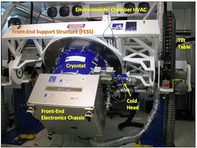
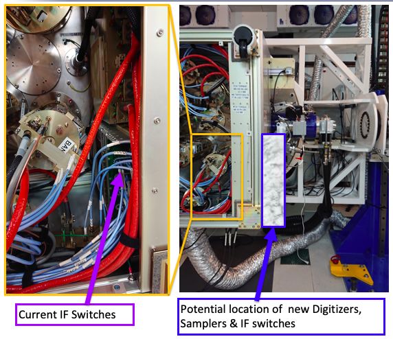
Specifications for 2nd Generation Doc #: ALMA-05.00.00.00-0049-A-SPE
 Date: 2021-01-08
 ALMA Correlator Page: 7 of 88

6.2.1 Coarsest 6.6 MHz (5% loss at 2.9 MHz (1% loss at Avoid BW smearing at lowest
channel resolution 35 GHz, 0.2PB for 35 GHz, 0.2PB for freq/max baseline for largest
 35km baseline) 35km baseline) correlated BW mode; 0.2PB =
 20% level of the primary beam
 response.

 Used for calibration, continuum,
 and high-z spectral scans
6.2.2 Finest 23.35 kHz (0.2 km/s 11.67 kHz (0.1 km/s Spectral Scans of line-rich
resolution at max at 35 GHz) at 35 GHz) Galactic sources, as well as
correlated bandwidth high-z absorption-line studies
6.2.3 Finest possible 2.33 kHz (20 m/s at 1.17 kHz (10 m/s at Very cold clouds,
channel resolution 35 GHz) 35 GHz) protoplanetary disk structure,
 small-body rotation,
 interplanetary probes
6.2.4 Bandwidth at 1.6 GHz 1.6 GHz Derived from max channels
finest possible required for 6.2.2 minimum goal
channel resolution
6.5.1 Elements in One to all antennas One to all antennas It shall be possible to form a
VLBI (Tied-Array) VLBI Tied-Array (aka Phased-
Sums Array) subarray from any
 number of available antennas,
 including those in the Main
 12m-array and the ACA.

In order to begin the discussion of how the new correlator and its prodigious data rates will impact
downstream subsystems, we provide a brief analysis of the peak output data rates in S7.

In S8, we describe options for deploying the new ALMA 2030 System, and find that a parallel
deployment strategy is likely the only viable option to avoid significant delays and science downtime.
The results of some initial fact-finding related to this option are also discussed (also see A.4). We
recommend that the HILSE eventually be upgraded to serve as a testbed for the 2nd Generation
Correlator.

Appendix A.2 describes our concerns related to doing a first coarse frequency channelization (FFT)
at the antennas, and why the CorrWG prefers that the correlator receive the data in time-series format.
Finally, Appendix A.3 describes options for overcoming the challenges presented by doing an
accurate delay correction, to inform future efforts to define an ALMA 2030 System-wide delay
correction strategy.
Specifications for 2nd Generation Doc #: ALMA-05.00.00.00-0049-A-SPE
 Date: 2021-01-08
 ALMA Correlator Page: 8 of 88

2 Introduction
 2.1 Goal of this Document and Charges
The primary goal and charges for the 2nd Generation ALMA Correlator Working Group, as assigned
by the ALMA Management Team, and addressed in this document are described below, see [AD06]
for more details:

The primary goal of the CorrWG shall be to develop specifications for the 2nd Generation ALMA
Correlator that should be deployed by 2030. Specifications are taken to mean both the detailed
technical requirements of the correlator itself, as well as, describing the key prerequisites that will
define the ultimate correlator design.

 ● In deriving the technical requirements CorrWG shall consult with digital correlator experts
 world-wide, and ensure equal representation of ideas and views across the ALMA
 partnership.
 ● As part of this activity, members of the CorrWG will participate in, and receive
 feedback from the “The ALMA2030 Vision: Design Considerations for the Next
 ALMA Correlator” Workshop to be held on Feb. 11-13 in Charlottesville, VA. By
 agreement within the working group, a representative subset of the CorrWG will also
 attend the “The ALMA 2030 Vision: Design considerations for Digitizers, Backend
 and Data Transmission System” Workshop to be held on March 11-13 in Mitaka,
 Japan, with the intent of sharing information and resolving issues that cross multiple
 systems.
 ■ We note that the Mitaka workshop was delayed until October 14-16, 2020, and
 virtual due to the Covid-19 pandemic. Much of the CorrWG did attend, but
 there has been little time to synthesize or incorporate the results.
 ● The CorrWG shall summarize the correlator workshop for the AMT.
 ● The CorrWG will also consult with the ALMA Integrated Science Team (IST) and ALMA
 Science Advisory Committee (ASAC), as well as, regional SACs for advice on the scientific
 requirements.
 ● The CorrWG shall present the detailed requirements and functionality in the form of both
 the minimum goals that achieve the science priorities of the ALMA2030 Roadmap and
 “stretch” goals that anticipate the forefront of technology (though likely production-ready)
 at the start of the next decade.
 ● The ultimate meaning of minimum and stretch goals shall be understood as the
 minimum for which a particular correlator design is considered to “meet spec”, while
 compliance with stretch goals may be used to distinguish between competing designs.
 ● Stretch goals, in particular, should have both technical and scientific justification.
 ● Areas of particular technical uncertainty should be clearly highlighted for future
 followup.
 ● Areas of consensus should also be clearly denoted.
 ● The CorrWG shall describe the likely pros and cons of different correlator architecture as
 they apply to ALMA Key science goals.
 ● The CorrWG shall propose prototyping for the Second-Generation ALMA Correlator,
 testing, and a deployment framework that minimizes ALMA science observing downtime,
 while not unduly prolonging the time to deliver new capabilities. The primary goal (for now)
 is to identify how various testing/deployment options could affect the ultimate
 correlator design/requirements.
Specifications for 2nd Generation Doc #: ALMA-05.00.00.00-0049-A-SPE
 Date: 2021-01-08
 ALMA Correlator Page: 9 of 88

 2.2 Applicable and Related documents
 2.2.1 Applicable Documents
The following documents are part of this document to the extent specified herein. If not explicitly
stated otherwise, the latest issue of the document is valid.

 Appl. Document Title ALMA Document Number
 [AD01] ALMA Product Assurance Requirements ALMA-80.11.00.00-001-D-GEN
 [AD02] ALMA Safety Manual ALMA-10.08.00.00-011-D-MAN
 [AD03] ALMA System Technical Requirements, rev C ALMA-80.04.00.00-005-C-SPE
 [AD04] The ALMA Development Roadmap Roadmap_public_20180415.pdf
 [AD05] ALMA Scientific Specifications and Requirements, rev. A ALMA-90.00.00.00-001-A-SPE
 Charge: Specifications for a Second Generation ALMA
 [AD06] ALMA-60.00.00.00-0173-A-SPE
 Correlator

 2.2.2 Related Documents
The following documents are referenced in this document, a number of other references are given in
the text as footnotes.

 Appl. Document Title ALMA Document Number
 [RD01] Front End and Digitizer Requirements ALMA-40.00.00.00-1612-A-SPE
 64 Antenna Correlator Specifications and Requirements 2008-08-07-ALMA-60.00.00.00-
 [RD02]
 (Baseline Correlator) 001-C-SPE
 [RD03] ACA Correlator Technical Specifications and Requirements ALMA-62.00.00.00-001-A-SPE
 The Atacama Millimeter Array Implications of Potential https://www.nap.edu/download/113
 [RD04]
 Descope 26
 Specifications and Clarifications of ALMA Correlator COMP-70.40.00.00-0007-A-MEM /
 [RD05]
 Details ScottCorrelNormalization.pdf
 NRC Talong Frequency Slice Architecture Correlator / ALMA_Talon_correlator_study_rep
 [RD06]
 Beamformer (AT.CBF) for ALMA ort_vRELEASE_2020-09-21.pdf
 ALMA-60.00.00.00-0148-B-MEM
 [RD07] Data Rate Impact of the ALMA Correlator Upgrade Project Correlator Upgrade Data Rate
 Memo.pdf
 ACA Spectrometer Technical Specifications and
 [RD08]
 Requirements
 ALMA-64.00.00.00-0005-B-SPE

 [RD09] ALMA Back End Electronics Design Description BEND-50.00.00.00-077-B-DSN

 ALMA Memo 561 (Delay Errors In Single- and Double- https://library.nrao.edu/public/mem
 [RD10]
 Sideband Interferometer Systems) os/alma/main/memo561.pdf

 https://almascience.eso.org/docume
 [RD11] ALMA Technical Handbook Cycle 8 nts-and-tools/cycle8/alma-technical-
 handbook
Specifications for 2nd Generation Doc #: ALMA-05.00.00.00-0049-A-SPE
 Date: 2021-01-08
 ALMA Correlator Page: 10 of 88

 ALMA Memo 607 (Digital Correlator and Phased Array https://library.nrao.edu/public/mem
 [RD12]
 Architectures for Upgrading ALMA) os/alma/main/memo607.pdf

 Implementing the concurrent operation of sub-arrays in the https://ui.adsabs.harvard.edu/abs/20
 [RD13]
 ALMA correlator 16SPIE.9913E..3KA

 The ALMA Phasing System: A Beamforming Capability
 https://ui.adsabs.harvard.edu/abs/20
 [RD14] for Ultra-high-resolution Science at (Sub)Millimeter
 Wavelengths 18PASP..130a5002M

 https://ui.adsabs.harvard.edu/abs/20
 [RD15] Phasing ALMA with the 64-antenna correlator
 12evn..confE..54B

2.3 Acronyms
A complete set of acronyms and abbreviations used in ALMA is maintained at the acronym list web
page, (also see the external website https://www.almaobservatory.org/en/siglas/). In addition,
throughout this report we will abbreviate “Second Generation ALMA Correlator” as 2nd Gen
Correlator.

3 Key Science Drivers
Below we list the three new key science drivers identified by the ALMA2030 Roadmap [AD04] for
the next decade, followed by the type of improvements required to realize them. The term “spectral
grasp” is shorthand for the ability to tune to a wide range of diagnostic spectral lines within a single
receiver band in a single observation, while “spectral range” indicates the need to access the full
(sub)millimeter frequency range visible from the ground, such as to accommodate a particular
source's redshifted spectral emission or the rest frequency of a unique diagnostic line transition.

 1. Origins of Galaxies: Trace the cosmic evolution of key elements from the first galaxies
 (z>10) through the peak of star formation (z=2-4) by imaging their cooling lines, both
 atomic ([CII], [OIII]) and molecular (CO), and dust continuum, at a rate of 1-2 galaxies per
 hour.
 + Spectral line sensitivity
 + Spectral grasp
 + Spectral range
 + Continuum sensitivity
 2. Origins of Chemical Complexity: Trace the evolution from simple to complex organic
 molecules through the process of star and planet formation down to solar system scales
 (∼10-100 au) by performing full scans of a whole frequency band at a rate of 2-4 protostars
 per day.
 + Spectral line sensitivity
 + Spectral grasp
 + Spectral range
Specifications for 2nd Generation Doc #: ALMA-05.00.00.00-0049-A-SPE
 Date: 2021-01-08
 ALMA Correlator Page: 11 of 88

 + Finer spectral resolution
 + Increased angular resolution
 3. Origins of Planets: Image protoplanetary disks in nearby (150 pc) star formation regions to
 resolve the Earth-forming zone (∼1 au) in the dust continuum at wavelengths shorter than1
 mm, enabling detection of the tidal gaps and inner holes created by nascent planets.
 + Continuum sensitivity
 + Increased angular resolution

These ambitious goals, while far-reaching from a science perspective, are unified by a relatively
small number of required upgrades: improved spectral line and continuum sensitivity, increased
spectral grasp and spectral range, and enhanced spectral and angular resolution. As proven by the
original Level One science goals, the capabilities driven by these new key science goals will enable
a vast range of new discovery space across the whole spectrum of ALMA science.

With the exception of spectral range (which is driven by the capabilities of the receivers), all of the
improvements needed to enable these ALMA2030 key science goals require a 2nd Gen ALMA
Correlator that can handle a wider instantaneous bandwidth (spectral grasp and continuum
sensitivity), correlate a higher number of bits (spectral and continuum sensitivity), accurately
correct for larger delay rates (higher angular resolution), produce more channels for a given
bandwidth (spectral grasp, higher spectral resolution), and allow the placement of numerous
independent spectral windows (spectral grasp).

4 Community Feedback
4.1 ALMA Correlator Workshop

The North American ALMA Science Center hosted an ALMA correlator workshop in Charlottesville,
VA on Feb. 11-13, 2020 entitled “The ALMA2030 Vision: Design Considerations for the Next ALMA
Correlator”. Hereafter, we simply refer to the “2020 Correlator Workshop”1. There were about 70
participants from around the globe, including correlator representatives from ALMA (BLC, ACAC,
TPS), JIVE, LOFAR, MeerKAT, ngVLA, NOEMA, SKA1-Mid, SKA1-Low, SMA, VLBA, and
VLITE. Presentations were given on the ALMA Development Program and the ALMA 2030
Roadmap, “Lessons Learned” from recent correlator projects, and “Emerging Technologies” from
on-going efforts. The presentations can be viewed at NextALMACorrelator_Presentations.
Additionally, there were three discussion/feedback sessions specifically geared toward the 2ndGen
ALMA Correlator on (1) open questions solicited from the participants, (2) optimal correlator
architecture, and (3) potential deployment options. Outcomes from the first two sessions are described
below, while the third is presented in S7. Additional feedback is provided in Appendix A.1.

 4.1.1 Outcome from Discussion of Key Questions Picked by Participants

1. Science benefits of XF or FX architecture? Do we need a first “F”? If so, where?

1
 http://go.nrao.edu/NextALMACorrelator
Specifications for 2nd Generation Doc #: ALMA-05.00.00.00-0049-A-SPE
 Date: 2021-01-08
 ALMA Correlator Page: 12 of 88

Correlator architectures are traditionally divided between “XF” (in which cross-multiplication in the
time domain is followed by Fourier transformation into the frequency domain) and “FX” (in which
Fourier transformation is done first, followed by cross-correlation in the frequency domain).
Complete Consensus: Many of the previous advantages of XF (with ASICs for the X-engine) can
now be surpassed by FX. There was agreement across all three Groups that FX offers significant
advantages:
 ● Upgrade flexibility; Easier to expand # of antennas
 ● Better isolation of channels (sinc^2)
 ● Better for large numbers of channels and easy to define windows of desired width and
 channelization
 ● Easier to do sideband rejection like 90deg Walsh function switching and fringe rotation
 ● Take advantage of the N x log(N) complexity the FFT algorithm can afford
Near Consensus that a first “F” could be necessary (i.e., FFX architecture)
FFX (Coarse Channelization => Fourier transform=> Complex Multiplication )
 ● An initial coarse channelization step may be required to reach the finest spectral resolution
 target of 1 kHz.
Majority of discussion on first “F” concerned where: antenna, or centralized with correlator
 ● Consensus: Final data transport requirements should drive the answer
 ● Multiple 400Gb/s transmissions on a single fiber are feasible (up to 25.6Tb/s), so it may not
 be necessary to reduce data volumes for transmission
 ● Concern was expressed about adding complexity to the antennas; however most felt that the
 savings in electronics complexity from an overall new design would still yield a net
 improvement
 ● There was concern that putting the first “F” at the antenna may result in efficiency loss
 (depending on the # of bits which are preserved)

2. Are there aspects of data processing which we should pull forward to the correlator?
 (gridding, weighting, WVR/Tsys application, baseline-dependent averaging,, ...)
Consensus (with caveats) – No strong driver for adding more capability in this area for near-term
ALMA 2030 goals, though this could change in the future if the number of antennas increases
significantly
 ● Removes ability to mitigate problems in data (as corrections are “locked-in”), so likely not
 desirable for science data (but see caveats)
 ● Takes large investment in commissioning at the telescope, and inhibits development of
 improvements in offline processing
 ● Caveats:
 ○ It is possible to do WVR correction now (allowing further time averaging on-line) but
 this is not being used except for VLBI. This option should be preserved. Research
 into whether WVR correction can be improved online or offline desirable – offline can
 more easily model changing corrections both forwards and backwards in time.
 ○ TelCal will likely need to apply Tsys and bandpass corrections on-line to flatten wide
 bandwidth before making channel-averages for QA0 assessment. However, the
 uncorrected channelized science data should be stored for offline correction.
 In the future:
 ● If RFI becomes significant, we may want to perform RFI excision in the correlator
 ● GPU processing could be interesting in the future, especially if the number of antennas
 increases significantly
Specifications for 2nd Generation Doc #: ALMA-05.00.00.00-0049-A-SPE
 Date: 2021-01-08
 ALMA Correlator Page: 13 of 88

3. What is the best way to correct for the instrumental delay?
Complete Consensus – Need more centralized method for delay application
Current issues with the ALMA delay mechanisms:
 ● Delay corrections are derived and applied in several different stages (based on centralized
 delay server) -- Bulk delay (Correlator Station Card, 250ps steps), Fine delay (TFB phase shift
 used for VLBI implementation of baseband delays normally done in the CDP), Ultra-fine
 delay (Digitizer clock-phase, 15.625ps steps), and Residual delay (CDPs,
Specifications for 2nd Generation Doc #: ALMA-05.00.00.00-0049-A-SPE
 Date: 2021-01-08
 ALMA Correlator Page: 14 of 88

4.2 Feedback from ALMA Science Advisory Committees

So far draft versions of the science drivers and requirements have been presented at:
 ● the ALMA Science Advisory Committee face-to-face meeting March 3, 2020
 ● the ALMA North American Science Advisory Committee face-to-face meeting (held
 virtually), May 28, 2020
Both groups expressed support for the on-going process, with no major additional suggestions.
Future community outreach activities will include: similar presentations to the East Asian and
European SACs, participation / discussion at the upcoming “ALMA 2030 Vision: Design
considerations for Digitizers, Backend and Data Transmission System” in October 2020”; and
webinars for registered ALMA users, towards the end of the process.
Specifications for 2nd Generation Doc #: ALMA-05.00.00.00-0049-A-SPE
 Date: 2021-01-08
 ALMA Correlator Page: 15 of 88

5 Key Assumptions and Critical Design Decisions
The second generation correlator design will depend upon a number of design decisions for the
upstream system (e.g., [RD01]), as well as potential updates to the System Level Requirements
[AD03] to reflect the ALMA2030 goals. In particular, decisions regarding the digitization and data
transport designs will have a critical impact.

 5.1 Key Assumptions
The assumptions described in this section, in effect form part of the 2nd Generation ALMA Correlator
requirements. If any of them are later proven to be unfounded, then all the correlator requirements
described in S6 will need to be reviewed for potential impact.

5.1.1 Receiver Design and Digitization Goals
Below we briefly summarize those aspects of the Front-End/Digitizer WG recommendations [RD01]
that directly affect the correlator subsystem.
 ● Instantaneous Bandwidth to be Digitized: ≥ 8 GHz per polarization
 per sideband, 16 GHz per sideband highly desirable
 ● Bandpass Shape (within digitizer baseband width): flat to within < 5.4 dB peak-to-peak
 ● Effective Number of Bits ≥ 5
 ● Digitizer sampling speed: > 40 GSamples/s
 ○ Implied Number of Basebands: 1 per sideband assuming 16 GHz per sideband IF

As in [RD01], for this document we assume that future ALMA receivers are likely to all be 2SB with
the exception of Band 1, which is expected to retain its current SSB design within the scope of likely
operation of the 2nd Generation ALMA Correlator. It is notable that there are still some open
questions regarding optimal design for Bands 9 and 10 depending on correlated bandwidth2, but for
the sake of simplicity we follow [RD01] in assuming that these will be 2SB eventually. As a result of
this assumption, bandwidths are written as per sideband quantities. Requirements essential to the
future operation of the current Band 9 & 10 receivers are, however, included for completeness (i.e.
ability to perform 90o Walsh switching).

For the purposes of this document, we assume that the [RD01] digitization goal of
ENOB ≥ 5 (99.6505% efficient3), together with any required digital signal processing and
losses due to clock jitter will yield an ADC/BE sensitivity of ≥98.5%. Additionally, there is a strong
desire in the astronomical community to avoid any gaps in the usable bandwidth (if there is more than
one baseband per sideband), or any significant difference between the correlated bandwidth and the
usable bandwidth. Toward this aim, we assume the digitized bandwidth will exceed the required
correlated bandwidth by a sufficient amount to prevent the edge roll-off from the digitizer anti-
aliasing filter from impacting the usable correlated bandwidth (also see [RD01]). It is also

2
 Using a DSB receiver with sideband separation in the correlator (e.g., 90o Walsh switching) results in double the
effective correlated bandwidth. This gives a sensitivity gain for continuum and spectral survey cases which is comparable
to that gained from the reduced Tsky contribution to Tsys for a sideband-separating receiver. Achieving very wideband
DSB receivers for Bands 9 and 10 may be considerably easier (and cheaper) than achieving a comparable bandwidth
sideband-separating design; a sideband-separating receiver design may only be competitive if the entire bandwidth in
both sidebands can be correlated, so that there is no loss of bandwidth compared to the simpler DSB option.
3
 Number of bits to efficiency values taken from Thompson, Emerson, and Schwab, Radio Science, Vol. 42 2007,
https://agupubs.onlinelibrary.wiley.com/doi/epdf/10.1029/2006RS003585
Specifications for 2nd Generation Doc #: ALMA-05.00.00.00-0049-A-SPE
 Date: 2021-01-08
 ALMA Correlator Page: 16 of 88

worth noting that while [RD01] does not include a specific
recommendation for the ALMA 2030 IF range (2-18 and 4-20 GHz are given
as possible options, with the final choice dependent on performance),
provided that twice the low end of the range is ≤ the maximum correlated
bandwidth per sideband, it will be possible to avoid the inter-tuning
“gaps” that presently impede efficient observation of spectral scans.

5.1.2 Correlator Design
Based on the unanimous feedback received from the 2020 Correlator Workshop (S4.1.1), we assume
that the 2nd Generation ALMA Correlator design will be FX: Fourier Transform first, converting
input signal samples in the time domain to the (complex) frequency domain; followed by complex
multiplication and accumulation, taking each piece of the input bandwidth and multiplying the data
flows for all antenna pairs in the array. The current technologies for correlator implementation impose
practical limits on the instantaneous bandwidth of signal that can be processed. Thus, it is likely that
the correlator design will actually need to be FFX, with an initial “F” stage that channelizes the
wideband signal into a moderate number of “chunks” (of order 10-100), followed by a second “F”
stage that produces the finer spectral sampling needed to meet the science requirements. The first “F”
stage then delivers a continuous time series of spectral ‘’chunks’’ that are presented to the second “F”
stage. (The first “F” stage could be either at the antenna, but see SA.2 for difficulties, or in the main
Correlator room.) The time-to-frequency transpose and the frequency-to-antenna transpose
operations needed before correlation are performed after the second “F” stage.

5.1.3 Correlator Subsystem Definition
The correlator subsystem processes all basebands (as defined in S5.1.4) delivered by each antenna in
the array to form all cross- and auto-correlation functions required for further astronomical data
analysis. ALMA consists of two arrays of antennas. We assume that the 2nd Gen Correlator will at
minimum be able to process the current 50x12m antennas of the Main Array, as well as the 12x7m
antennas + 4x12m Total Power antennas of the Atacama Compact Array (ACA, also known as the
Morita Array). Such observations shall be possible via independent subarrays, or with all 66 antennas
combined into a single array. Presently, the data from these two arrays are typically correlated by the
Baseline Correlator (BLC, [RD02]) and the ACA Correlator (ACAC, [RD03]), respectively, though
ACA data can optionally be processed by the BLC.

Presently Total Power data is typically processed by the ACAC, but in the near future, such data will
be processed by the new ACA Spectrometer (ACAS, [RD08]), targeted to be commissioned for
general use in Cycle 9. While we assume that the 2nd Gen Correlator must be able to correctly process
ALMA Total Power data, in addition to interferometric data, we note that it may be operationally
advantageous to upgrade and optimize the ACAS for spectral compatibility to the 2nd Generation
Correlator for Total Power observations. We assume that even if this path is chosen, that it will still
be possible to use the 4x12m Total Power antennas that are co-located with the compact 7m-array
interferometrically with the 2nd Gen Correlator. Especially for high frequency observing, the
addition of the co-located 12m antennas to the 7m-array can be critical for accurate calibration.

For the current BLC, the Correlator Data Processing nodes (CDPs) are sometimes considered separate
from the Correlator, though many of the important “correlator” functions are performed there,
including the FFTs (the ‘F’ in “XF”), sub-band stitching, Van Vleck corrections, normalization by
the autocorrelations, and spectral averaging to name a few. It is also notable that the correlator is
Specifications for 2nd Generation Doc #: ALMA-05.00.00.00-0049-A-SPE
 Date: 2021-01-08
 ALMA Correlator Page: 17 of 88

presently responsible for performing the instrumental delay tracking (the station cards apply the bulk
delay, while the baseband and residual delays are applied in the CDPs). At this time no detailed
system-wide delay tracking plan is available for ALMA2030. In this document we specify
requirements for the “combined correlator subsystem” because some functions that are currently
handled in software by the CDPs could be done in hardware/firmware in a future design. The
expected correlator input is described in S5.1.7 and the output is described in S6.7 of the requirements.

5.1.4 Baseband Definition
Our definition of one baseband channel is closely linked to the electrical intermediate frequency (IF)
bandwidth delivered by a Front-End receiver and to the sampler actual performance. One baseband
channel bandwidth (BB) is defined here as the unit of digitized electrical bandwidth presented to the
correlator. This bandwidth may differ from the sampler input bandwidth, depending on the digitizer
module design and performance (in particular, the adopted exact sampler clock rate and anti-aliasing
filter properties). The correlator must process the entire BB bandwidth presented to the correlator,
although it need only correlate the scientifically useful part of this band. For a 2SB receiver (S5.1.2),
there will be a minimum of four BBs, two for each polarization per sideband; more BBs may be
required and presented to the correlator if a single digitizer (per sideband and polarization) cannot
cover the IF bandwidth of the receiver.

Broader BBs allow the processing of very broad spectral lines (as needed, e.g., for galaxy clusters or
Solar observations) as well as collections of individually-narrow spectral lines or related isotopic
molecular species distributed over a wide instantaneous bandwidth. This suggests that very broad
BBs are desirable scientifically, especially if they provide a high signal-to-noise ratio performance.

Smaller increments within a BB are called spectral channels and spectral windows. The smallest
frequency increment produced at the output of the correlator subsystem is called a spectral channel.
The width of such a channel is set by the actual correlator design, or by internal averaging required
to reduce the output data rate to a reasonable level. A spectral window4 (sometimes called a sub-band)
is a collection of contiguous spectral channels which share the same frequency widths and spectral
responses. Spectral windows may overlap in frequency. The bandwidth of a spectral window is at
most the bandwidth of an individual BB.

Many science cases may require independently configuring multiple spectral windows within a single
BB, e.g., to allow observers to “zoom in” on interesting parts of the spectrum with different spectral
resolutions, while also maximising continuum bandwidth (for calibration at least). Thus, each spectral
window must have adjustable frequency centers, bandwidths, and spectral channel widths (S6.8).

5.1.5 Maximum Baseline Lengths
The maximum delay rate that has to be taken into account in the correlator corresponds to the longest
east/west extension of the Array, while the maximum total delay to be buffered depends on the longest
baseline in any direction (in addition to the maximum fiber length difference). Since the 2nd
Generation Correlator may operate for a significant fraction of the active life of ALMA, the possibility
that additional pads are added to increase the length of the maximum baselines has to be taken into
account.

4
 In the current ALMA terminology a spectral window may include all polarization products thus requiring correlation of
a BB pair.
Specifications for 2nd Generation Doc #: ALMA-05.00.00.00-0049-A-SPE
 Date: 2021-01-08
 ALMA Correlator Page: 18 of 88

The SE arm of the Array could be extended further along the same direction, since after about 12 km
from the center of the Array, it could merge with the gorge along Route 27. This could continue for
another 10 km until the National Flamingo Preserve near La Pacana. At that point the geography
becomes significantly more complex, and a more or less linear extension becomes complicated (road
access would be challenging), until possibly the border into Argentina has been crossed. The NE arm
can be extended into Bolivia for another ~10 km into the Laguna Verde/Laguna Blanca area before
encountering a more complex landscape. The EW arm can be extended easily across the Atacama
Valley for about 30 km before reaching the Valle La Luna area. The extension in that direction,
however, comes with a significant reduction in altitude (~2000m lower than the Chajnantor Plateau),
which would significantly affect the performance of the Array at high frequencies. All these
extensions may be hampered by external geopolitical factors, such as the need to get the pertinent
allocation of the land to set the pads, difficulties in placing pads outside the territory of Chile, etc.
Taking into account all the above considerations, we assume that the maximum East-West extension
during the operation phase of the 2nd Generation Correlator (i.e., Stretch Goal) will be =
Specifications for 2nd Generation Doc #: ALMA-05.00.00.00-0049-A-SPE
 Date: 2021-01-08
 ALMA Correlator Page: 19 of 88

Figure 1: Representative extended configuration with stations added to the West (OSF-AOS access
road, including existing OSF-TF stations), North (within the ALMA concession, as limited by the
Paso Jama road) and South (within the Atacama Astronomical Park). Note that obtaining N-S extent
is crucial for complete uv coverage, especially for sources near the equator. The coordinates are
relative to the array centre currently used for computing delays online for existing array
configurations.

Feasibility testing so far has demonstrated that the existing LO and DTS systems can be used between
OSF and AOS. However, the usability of the LLCs is so far untested, and the expectation is that the
LLCs will not be usable in their normal way. Thus we assume that a more extended array will likely
operate with the LLCs either operating differently, or not being used at all, on the assumption that
atmospheric phase fluctuations dominate over fiber path length variations on the relevant temporal
and spatial scales of astronomical phase referencing. This issue is, however, not relevant to the
correlator subsystem.

5.1.6 Time Synchronization
The meaning of time synchronization in this section is: the mechanism for synchronizing the
correlator operations to the ALMA telescope timing references.

The CLOA (Central Local Oscillator Article ) is the ALMA telescope entity responsible to generate
the timing reference signals to be distributed to the ALMA telescope components by means of the
Back End infrastructure. No significant changes to the CLOA are expected during the lifetime of the
2nd Generation Correlator, and its resources can therefore be used for synchronization purposes. Two
sets of timing Reference signals are generated by the CLOA:

 ● Low frequency
 ○ 125[MHz]
 ○ TE → 48[ms] period square wave signal
 ○ 2[GHz]
 ● High Frequency
 ○ produced by the Photonic References and intended to synchronize the First LO (see
 [RD09], sections 3.6.3 and 3.6.4)

The correlator gets two low-frequency signals from the CLOA (see [RD09], section 3.6.1)

 ● 125[MHz] sine wave, 8[dBm], 50[Ohms]
 ● TE LVDS

The 125[MHz] is derived from an ultra-stable 5[MHz] oscillator. The TE signal is made using as time
reference the 125[MHz], and its phase is synchronized to a 1PPS signal output of a GPS5. The usage
of the previously listed signal by the correlator is not mandatory, but, those are the only available
signals which provide a time reference to the correlator. The correlator must process the samples
from the antenna according to the current telescope conditions, and the time reference signals
provide a time-base for this. We further assume that scans start and stop on TE boundaries.

5
 A 1 PPS signal is also emitted by the Central LO. Together with the GPS and TE signals it is used by the BLC to provide
timing sanity checks for Phased-array observing.
Specifications for 2nd Generation Doc #: ALMA-05.00.00.00-0049-A-SPE
 Date: 2021-01-08
 ALMA Correlator Page: 20 of 88

5.1.7 Metadata that the correlator expects
In addition to the actual digitized data, the correlator requires certain other information to be delivered
in real-time. The details depend on the system-level implementation of basic functions such as
digitization, timing, application of delays, and the like. While this is known for the current system
(e.g., S5.1.6), there is not yet a design for the ALMA2030 system (see S5.2). It is clear however that
the correlator will require the following:
 ● Time stamps and synchronization patterns, to align the data from the different antennas;
 ● Verification information, to monitor missing samples and communications problems (e.g.,
 check sums, bit error rates, etc.);
 ● Subscan sequence specifications, both to label the data properly and potentially to allow
 application of the correct delay models;
 ● Sub-integration flags6 (if any) and excision controls, to pass along flags upstream of the
 correlator system (if any) and to control any automatic flagging done by the correlator itself
 (e.g., based on high power levels);
 ● Delay information (delay events and/or delay models [including validity intervals]);
 ● WVR data for real-time phased-sum path length correction (if desired);
 ● Total power information, it there is digital processing upstream of the correlator system (if
 not, the correlator can calculate power levels itself), together with corrections if this
 information comes from a separate detector rather than from digitiser statistics;
 ● Any other calibrations which must be applied in real-time (e.g., complex gains from TelCal);
 ● Information related to tied-array beams (e.g., complex antenna weights to be used in the tied-
 array sum, including delay offsets from the subarray delay centres and sensitivity weighting).

5.2 Critical Design Decisions for ALMA2030
In this section, we describe critical decisions that are required to facilitate an actual 2nd Generation
ALMA Correlator design. Each open issue is followed by a brief explanation from the point of view
of the Correlator Subsystem/CorrWG:
Digitization
 1. How many basebands of data will be delivered to the correlator?
 a. Although the correlator subsystem needs a decision on the number of basebands (as
 defined in S5.1.4) to be made early in the process, it is largely agnostic about the actual
 number. This is because the correlator will need to divide data into suitably sized
 frequency "chunks" for optimal processing that are almost certainly smaller than the
 adopted baseband width in any case.
 b. The Front-End/Digitizer WG report recommends avoiding a second down-conversion
 thereby producing only one baseband signal per sideband, and the CorrWG has no
 concern with this suggestion (assuming that it is feasible to achieve it on a reasonable
 development timescale).
 c. For ease of testing and implementation the correlator will likely be built, and at least
 initially deployed and tested, one baseband at a time.
 2. What will the usable bandwidth of each baseband be? It is highly desirable that the usable
 bandwidth delivered to correlator be >= the maximum correlated bandwidth.
 3. How many bits will the transported data have?
 a. The Front-End/Digitization WG recommends that the effective
 number of bits be ≥ 5, and we concur with this goal in terms of

6
 Flags which apply on timescales as long or longer than an output integration need not be applied in the correlator, while
sub-integration flags must be applied during correlation.
Specifications for 2nd Generation Doc #: ALMA-05.00.00.00-0049-A-SPE
 Date: 2021-01-08
 ALMA Correlator Page: 21 of 88

 the expected digitization efficiency. However, the correlator
 needs to know how many physical bits (which will likely range
 from 6-8) will be transmitted, in order to design the
 correlator, as well as the requisite requantization
 correction.
 b. The physical number of bits will also determine the requisite data rate to be
 transported.
Data Transport
 4. It remains an open question whether the data rate of the full time series data produced by the
 ALMA2030 Front-ends / digitization can feasibly be transported to the correlator without
 incurring infeasible cost. A potential remedy would be to perform a first Fourier Transform
 with relatively coarse spectral resolution at the antennas.
 a. Because it will fundamentally dictate the nature of the data that is transmitted to the
 correlator (time-series vs spectral) and how it must be processed, and corrected, the
 Correlator Subsystem is keenly interested in this issue, and requests that addressing
 this issue be of highest priority for moving forward with the ALMA2030 Roadmap.
 b. After weighing the pros and cons, the CorrWG would strongly prefer that all post-
 digitization data manipulation occur within the correlator subsystem, i.e. no first “F”
 at the antennas unless data transport is otherwise infeasible. A complete description of
 our concerns are described in A2.1.
 c. Beyond the raw data itself, a complete list of all the information that needs to be
 transmitted needs to be developed and included in the data transport question. The
 additional information required by the correlator is described in S5.1.7.
 d. How exactly will the data be packetized?
 i. In particular will timestamps be used and exactly how will that be
 implemented? What will the timestamp accuracy be?
 e. What will the data transport protocol be?
 5. What will the maximum instantaneous data rate of the transported data be?
 6. Can the data be transmitted to the OSF without any significant loss in data integrity?
 a. At the 2020 Correlator Workshop it was unanimously agreed that placing the 2nd Gen
 Correlator at the OSF would convey many advantages, see below for two key
 examples, however we need to know if this is feasible ASAP.
 i. The HVAC needs of the 2nd Generation ALMA Correlator will be
 considerably reduced if it can be located at the OSF rather than AOS (as well
 as its maintenance). For the HVAC, the savings will be of order a factor of 2.
 ii. The complexity of deployment and commissioning, as well as future
 maintenance and trouble-shooting of the 2nd Gen Correlator will be
 significantly reduced if it can be located at the OSF.
Power Infrastructure
 7. After construction, the power consumption of a correlator (and its HVAC needs) represents a
 significant recurring operational cost. Presently there are no concrete system-wide constraints
 on the ALMA2030 power needs overall or on the correlator power budget specifically. We
 urgently need to know the upper limit on correlator power consumption.
 8. Will the 2nd Gen Correlator be backed-up with UPS power? If not additional protections will
 be needed in the final design.
 a. The UPS could be in the form of short-term protection of the whole subsystem against
 brief glitches, or longer term protection for just key hardware.
Downstream Capabilities
Specifications for 2nd Generation Doc #: ALMA-05.00.00.00-0049-A-SPE
 Date: 2021-01-08
 ALMA Correlator Page: 22 of 88

 9. What is the likely maximum sustainable instantaneous dump rate from correlator to storage
 in the ALMA2030 era? Data Processing Constraints? etc
 a. It would be a waste to build a correlator that greatly exceeds (by orders of magnitude)
 the foreseeable ability of the downstream subsystems to handle the data rate. We need
 near, mid, and far-time look aheads that span at least the next decade to understand
 what is likely to be possible.
Other (Cross-Subsystem) Issues
 10. We need an ALMA2030 System-wide efficiency goal in order to know the number of bits the
 correlator needs to process. A system-wide value of 96% is typically being assumed (i.e., the
 product of digitization and correlation losses).
 11. We need an ALMA2030 System-wide specification on the maximum allowed power variation
 across each IF passband (the FE/Digitizer WG Report only recommends a constraint for the
 digitizer portion of 5.4 dB) [Note this item does not directly affect correlator design but was
 identified as a notable missing specification for the ALMA2030 wideband system, i.e., a
 wideband equivalent to [AD03] 7.2.21, Requirement 272].
 12. We need a cross-subsystem strategy for how to implement delay tracking, time
 synchronization, and communications in the full ALMA2030 system.
 13. How do we ensure return-to-phase for the system as a whole? Various subsystems, hardware
 and software, are inter-related.
 14. We need a system-wide requirement and strategy for preserving the X-Y phase in the system
 over (up to) several hours in order to calibrate polarization calibrators over the required range
 of parallactic angle coverage (> 60 degrees).
 15. Will WVR continue to be applied offline (online is a combination of TelCal and Correlator
 System)?

6 Correlator Requirements
The Second Generation ALMA Correlator requirements are presented as “minimum” and “stretch”
goals. The “minimum” requirements are those required to meet the near-term goals laid out in the
ALMA2030 Roadmap [AD04], specifically at least doubling the correlator bandwidth of the ALMA
System. The “stretch” requirements anticipate what will likely be possible at the start of the next
decade (considering likely technology readiness), and incorporate requirements for the ALMA2030
Roadmap longer-term goals such as extended baseline lengths, and additional collecting area. The
requirements are broken into topical subsections, and within each subsection, the requirements are
presented as both short summary table entries, as well as descriptive text, both denoted by
subsubsection numbers -- in case of confusion, the text shall be considered as defining the full
requirement.

6.1 Basic Properties

Parameter Minimum Req’mt Stretch Goal Comment
6.1.1 Number of 66 (all 12m + 7m) >=80 total antennas Main Array: 50x12m +
antenna inputs in subarrays and all in subarrays and all ACA: with 12x7m and 4x12m =
 together, but together, but 66; Stretch: Recover original
 expandable expandable design, 64x12m in Main Array
Specifications for 2nd Generation Doc #: ALMA-05.00.00.00-0049-A-SPE
 Date: 2021-01-08
 ALMA Correlator Page: 23 of 88

6.1.2 Maximum 8 GHz per pol per Max Digitizer Stretch goal strongly
bandwidth that can sideband (2x current) Design: present preferred.
be correlated but expandable. projection 16 GHz Allowed observing setups will
 per pol per sideband need to impose data rate
 (4x current) limitations.
6.1.3 Correlation 1, 2, or 4 1, 2, or 4 Science motivation for 1 pol
products (XX or YY; XX and (XX or YY; XX and weak after significant
 YY; XX, YY, XY, YY; XX, YY, XY, improvement in overall spectral
 YX) YX) resolution

6.1.4 Correlator 97.5% 98.5% Assumes system wide efficiency
efficiency (minimum (4-bit multiplication (6-bit multiplication goal of >96%, and upstream
number of bits for + DSP losses) + DSP losses) digital efficiency of ~98.5%
multiplication + DSP (ADC > =5-ENOB+losses).
losses) DSP=digital signal processing
6.1.5 Max Delay 400us (35 km East- 1000us, same as Note that the overall delay
compensation West baseline + BLC (40Msample compensation strategy for
distance, buffer time 56km fiber @ 40Gs/s, 240Mbit ALMA2030 is not yet clear
range, and buffer difference; if 6-bit/sample)
capacity per station 16Msample @ Buffer time is sum of
and baseband 40Gs/s, 96Mbit if 6- atmosphere geometric delay
 bit/sample) difference + fiber (2e8m/s)
 delay difference
6.1.6 Power TBD =< now Current (hardware + computing)
Consumption BLC=165 kVA + 25.3 kVA +
 HVAC
 ACAC+ACAS=66.7 kVA + 20
 kVA + HVAC

6.1.1 Number of antennas
The minimum requirement is to correlate 66 antennas, i.e., the current number of ALMA antennas.
The Second Generation ALMA Correlator should have subarray modes which enable it to produce
not only cross-correlations from 50 x 12m and 12 x 7m arrays but also auto-correlations from the 4 x
TP array. All the products from these three arrays then have the same spectral response. In this way,
we avoid the need for any frequency synthesis to match one correlator to another. The bottom line is
that the Second Generation ALMA Correlator should produce cross-correlations from both 12m and
7m arrays and auto-correlations from the TP array, for a total of 66 antennas. Additionally, it shall
be possible to correlate all the antennas together in a single observation.

The stretch goal for the number of antenna inputs is related to the longer term ALMA 2030 Roadmap
[AD04] goal of increasing the main-array’s collecting area, though there is no information at this
stage as to how many new antennas this goal would entail. The original ALMA design envisioned 64
x 12m antennas in the main array, with the drop to the current 50 x 12m antennas a consequence of
the 2005 ALMA Re-baselining Activity for cost-savings [RD04]. However, the improved image
fidelity afforded by the full 64 antenna main-array configurations, especially for longer baselines, is
well-documented [RD04], so this forms the lower bound of the stretch goal, with further
Specifications for 2nd Generation Doc #: ALMA-05.00.00.00-0049-A-SPE
 Date: 2021-01-08
 ALMA Correlator Page: 24 of 88

expandability desirable. The stretch goal is thus a total of at least 80 antenna inputs (64 x 12m + 12
x 7m + 4 x 12m, TP).

6.1.2 Maximum bandwidth that can be correlated
The ALMA 2030 Roadmap [AD04] states that the most important near-term goal is to at least double
the bandwidth of ALMA, including the 2nd Gen Correlator, in order to achieve the ambitious new
key science goals described in S3. Thus, the smallest maximum correlated bandwidth (MCB) goal is
8 GHz per polarization, per sideband (2x current). However, since the Roadmap was begun, there has
been significant progress in developing wider bandwidth receivers (e.g. ESO is building a Band 2
receiver with a likely IF bandwidth of >=16 GHz (required >=12GHz)7; an upgraded Band 6 being
studied by NRAO will likely have an IF bandwidth of 12 GHz8; and NAOJ has demonstrated a Band
7/8 concept with 17 GHz IF bandwidth)9. Additionally, digitizers that can handle up to 40 Gsample/s
have been demonstrated, enabling direct instantaneous sampling of an IF range of 0-20 GHz, yielding
at least 16 GHz of usable bandwidth per pol, per baseband. Therefore, the stretch goal is to allow
for a maximum correlated bandwidth equivalent to the maximum that the upgraded
digitization/DTS system can produce, which at this moment appears likely to be 16 GHz per pol
per sideband (4x current). We further amend the minimum goal to explicitly require the ability
to expand the bandwidth if it is initially limited to 8 GHz per pol, per sideband due to cost or
scheduling constraints. These requirements are consistent with those of the Front-End/Digitizer WG
[RD01]. All other applicable requirements in this document must be fulfilled at the maximum
correlated bandwidth.

From a technology point of view, a number of recent and planned correlator designs suggest that a
correlated bandwidth of 16 GHz per pol, per sideband for 66 to 80 antennas (S6.1.1) is feasible in the
ALMA 2030 timeframe as described at the 2020 Correlator Workshop. Examples include the SMA10
(8 antennas, MCB = using two independently tunable, but overlapping RF receivers 12 GHz per pol
(dual polarization), per sideband, or 24 GHz single pol, per sideband), NOEMA11 (12 antennas, MCB
= 8 GHz per pol, per sideband), and the upcoming SKA-mid Phase 112 (197 antennas, MCB = 5 GHz,
per pol) correlators. Thus, these current and upcoming correlators are approaching ALMA’s needs in
#Antenna^2 x MCB space. Indeed, a recently completed Cycle 7 North American ALMA
Development Study carried out by the NRC describes a proof of concept for adapting the extensively
reviewed SKA-mid Phase 1 correlator design to ALMA with 8 GHz per pol, per sideband and 80
antennas, which is potentially expandable to 16 GHz per pol, per bandwidth [RD06].

It is notable that while the technology upstream of, and including the correlator is reaching a maturity
consistent with the desired 16 GHz per pol, per sideband goal (4x current) with 66 to 80 antennas, the
downstream subsystems (Telcal, Archive, Global Data Transport, and Data Processing) have not yet
demonstrated that they would be able to handle the prodigious data rates (or volumes) that would be
afforded by the recommended ALMA2030 system. A modern FX correlator will natively produce ~1
million of channels, as compared to the maximum of 30,720 available with the BLC or ACAC (though
the ACAC itself produces many more channels natively that are averaged down using frequency

7
 https://www.aanda.org/articles/aa/full_html/2020/02/aa36777-19/aa36777-19.html
8
 https://zenodo.org/record/3240369
9
 https://www.aanda.org/articles/aa/full_html/2020/08/aa38713-20/aa38713-20.html
10
 SMA Presentation: https://osf.io/8dt2c/
11
 NOEMA Presentation: https://osf.io/mcwkf/
12
 SKA-mid Phase 1 Presentation: https://osf.io/k4jpt/
You can also read