Technology and front end in MMO
←
→
Page content transcription
If your browser does not render page correctly, please read the page content below
part of Aker
              part of Aker

Technology and
front end in MMO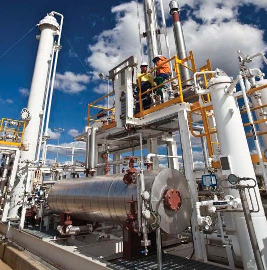
Technology and front end in MMO
Specialists at your service

      Maintenance, modifications and operations              price, technical solution and planned execution.
      represent a growing market for Aker Solutions          We perform a large number of MMO-related stud-
      as existing offshore and land-based installa-          ies every year.
      tions mature. Our major front-end engineering
      and design (Feed) and modification projects            Our study groups should be your preferred choice
      in the MMO area include drilling upgrades, tie-        when you need somebody to take on challeng-
      ins, low-pressure production upgrades, water           ing study work, from initial idea to feasibility and
      injection upgrades and swivel replacements.            choice of concept. We deliver studies which clear-
                                                             ly present the scope of your EPCI project, cost
      Vast experience with MMO projects for the oil and      estimates, risk profiling, technology gap analysis
      gas industry has enabled us to develop technol-        and technical evaluation of the concepts studied.
      ogy and front end specialist teams. These col-
      laborate closely with our corresponding teams in       Owing to the significance of the Feed, it is impor-
      field development (FD), achieving synergies to the     tant that a study group has the relevant expertise.
      client’s benefit in both FD and MMO projects.          We acknowledge the complexity of your Feed
                                                             and have made it possible to draw on technical
      Having in-house technology and front end special-      expertise from all our locations. When receiving
      ist teams at our disposal benefits you as our client   a Feed assignment, we establish a study team
      in every area from efficiency to price and technical   which embraces all the necessary expertise, be it
      solutions.                                             in platform upgrades, tie-ins or other challenging
                                                             modifications.
      These specialist services are staffed by highly
      qualified experts in the specific areas, and are in-   Your preferred choice for world-class front end ex-
      corporated in MMO projects as required and when        pertise in MMO is located in Aberdeen, Stavanger,
      performing stand-alone projects/studies.               Bergen, Trondheim and Kristiansund.

      Technology and front end

      We are experiencing a big demand for specialist
      services related to MMO because our clients need
      to get work done on their existing platforms and
      plants.

      We have world-class technology groups at key
      locations around the North Sea, performing
      advanced analyses on behalf of international oil
      companies. Our technology groups collaborate
      closely with the study teams at these locations,
      enabling clients to make precise evaluations of the
      scope, cost and technical implications of planned
      modifications to offshore platforms and land-
      based plants.

      Front end services

      When an oil company needs to award a large
      engineering, procurement, construction and instal-
      lation (EPCI) modification project, the Feed study
      often serves as the tender basis for contractors.
      That makes it crucially important for the scope,

                                                                                         © Aker Solutions 2010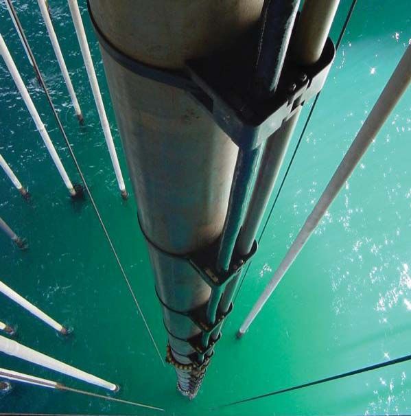
Technology services                                 The technology services we offer to the MMO
                                                                              market include:
                          We have concentrated our technology specialists
                          in hubs around the North Sea in order to create       • riser and umbilical analysis
                          environments in which people thrive and share         • structural reanalysis
                          their knowledge.                                      • structural fire analysis
                                                                                • structural analysis
                          These groups make us a world-class performer          • structural inspection and maintenance
                          for structural analyses, including riser, structural    programme (SIMP™)
                          fire, hydrodynamic, inspection and global analysis • inspection and maintenance technology
                          as well as reanalysis of floaters and fixed installa- • technical integrity management services (TIMS)
                          tions.                                                • 3D laser scanning
                                                                                • advanced hydrodynamic analysis
                          We also deliver technology services spanning from • weight and stability services
                          flow assurance to three-dimensional laser scan-       • asset management
                          ning, hazard and operability (Hazop) and asset        • flow assurance
                          management.                                           • dynamic process simulations
                                                                                • Hazop analysis
                          Our specialists often play a vital role in ensuring   • functional safety instrumented systems
                          progress with larger projects, solving complex
                          issues efficiently and precisely in order to achieve
                          optimum solutions.

For more information on
our technology and
front end services in
MMO, please contact

Stavanger
Geir Endresen,
manager, on
+47 92 43 16 01 or at
geir.endresen
@akersolutions.com

Bergen
Rune Ellefsen,
manager, on
+47 90 16 52 14 or at
rune.ellefsen
@akersolutions.com.

Visit us at
www.akersolutions.com

                                                                                                          © Aker Solutions 2010
Front end studies in MMO
From opportunity to defined concept

                            We help to define the scope, price and techni-                We deliver optimum modification solutions
                            cal consequences of modification or mainte-                   through a combination of screening and evaluation
                            nance projects, and bring our clients through                 of available products and technologies. Purpose-
                            all decision gates until feasibility is confirmed             designed process systems, risers and transport
                            or the concept defined.                                       systems are delivered, along with any kinds of
                                                                                          support facilities.
                            The main objectives for our front end group are to:
                                                                                          Front end study deliverables also include:
                            • support client modification processes
                            • maximise the value of client assets                         • cost estimates
                            • develop the concept, cost estimates and                     • risk profiling
                              execution plan for the project                              • technological gap analysis
                                                                                          • technical evaluation
                            We use a staged process developed to accom-
                            modate client decision gates. A proven project
                            execution model is our guide to success.

                                          M1A                   M1B                               M1C                           M1D
                                          Alternatives          Feasibility concepts              Concept selected              Concept complete
                                          generated             selected

                                                          Phase 1: Feasibility & concept
                            Stage 1A                     Stage 1B                      Stage 1C                      Stage 1D

                            Opportunity                  Feasibility                   Concept                       Concept
                            appraisal                    studies                       selection                     definition
For more information on
our front end studies
capabilities, please
contact

Stavanger
Geir Endresen,
manager, on
+47 92 43 16 01 or at
geir.endresen
@akersolutions.com
                                                                                                  “A guided study
Bergen
Rolf Monsen, manager,
on +47 99 60 97 83 or
                                                                                                  execution with
at rolf.monsen
@akersolutions.com                                                                                a proven record
Trondheim
Kristian Risdal, man-                                                                             of success”
ager, on +47 99 61 79
49 or at kristian.risdal@
akersolutions.com

Visit us at
www.akersolutions.com

                                                                                                                          © Aker Solutions 2010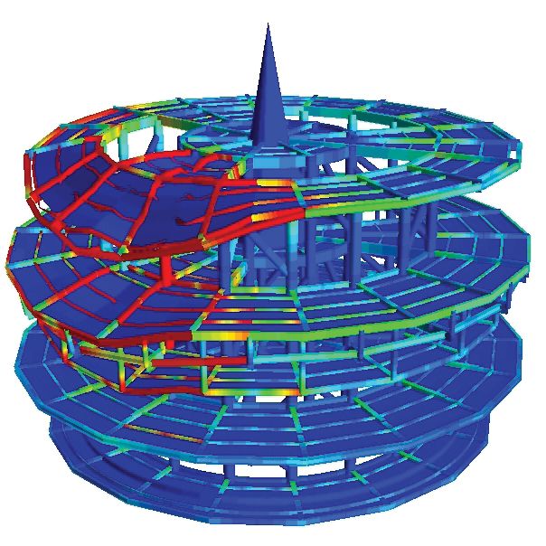
Front end studies in MMO
Reference list
This list is not exhaustive

Start   End
year    year    Client           Project title

2010    2010    Statoil          Pan Pandora tie-back to Gullfaks C or Visund FEED (Class D)

2009    2010    Statoil          Gullfaks A drilling facility upgrade (Greenfield and brown field upgrade) FEED

2009    2010    Statoil          Kristin low pressure production (LPP) & tie-back Q&K satellite to Kristin FEED

2009    2010    Statoil          Åsgard minimum flow feasibility & concept studies

2009    2010    Statoil          Åsgard A swivel replacement FEED

2009    2010    Statoil          Heimdal depressurisation study (Class B&C)

2009    2009    Statoil          Gudrun tie-in to Sleipner FEED

2009    2009    Statoil          Marulk tie-in to Norne FEED

2009    2009    DetNorske        Draupne WHP concept study
                                 Gullfaks A&C upgrading of SPM 1&2 (Single point mooring system) life time
2008    2009    Statoil
                                 extension study
2008    2009    Statoil          Heidrun PPL FEED
                                 Snorre A upgrading of existing drilling modules w/options. Brown field study.
2008    2009    Statoil
                                 FEED
2007    2008    Dong             Oselvar WHP feasibility/concept/FEED

2007    2008    Norske Shell     Draugen redevelopment - power - concept study
                                 Heidrun PPL, B, C and FEED studies. Modifications related to increased gas
2007    2008    Statoil
                                 capacity
2006    2007    ConocoPhillips   Eldfisk II feasibility

2005    2006    Statoil          Snorre/Vigdis IOR FEED

2004    2005    Statoil          Statfjord late life pre-engineering

                                                                                         © Aker Solutions 2010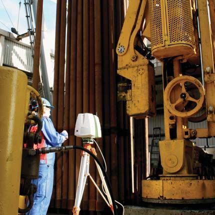
Riser and umbilical analysis
Fatigue, VIV and interference

                           Umbilicals (life-supporting cables for your sub-         Areas of expertise include:
                           sea equipment) and risers need to be designed
                           for each specific oil and gas field, since condi-        • field development studies
                           tions vary dramatically between them. Our                • global strength analysis, connected and discon-
                           expertise helps to design riser and umbilical            nected
                           configurations to optimise your cross-section            • detailed fatigue analysis for flexible risers, Bflex
                           and to ensure safe operation throughout a                • VIV analysis
                           field’s producing life.                                  • on-bottom stability analysis
                                                                                    • free-span analysis
                           We perform global strength analysis, including           • crossing analysis
                           operational and accidental conditions as well as         • interference analysis
                           fatigue, vortex-induced vibration (VIV) and interfer-    • wear analysis
                           ence analysis. Before challenging conditions arise,      • installation analysis
                           you need to know how your risers will behave and         • J-tube pull-in analysis
                           what they can withstand. Optimising your configu-        • coupled analysis for interface details
                           rations at an early stage with a fit-for-purpose field   • flexible and steel catenary risers.
                           architectural design will help to maintain focus on
                           the individual riser or umbilical.                       Tools include:

                           Our specialists perform all kinds of analyses using      Flexcom
                           a combination of standard software packages for          Vivana
                           slender marine structures and specialised pro-           Shear7
                           grammes – such as Bflex for detailed analysis of         Bflex
                           interactions and utilisation of the different layers     Abaqus
                           in a flexible riser. Deep insight into a wide variety    Usfos
                           of structures and their complex wear and tear            Hyber
                           scenarios makes us one of the market leaders for         Orcaflex.
                           risers and umbilicals.

For more information on
our riser analysis capa-
bilities, please contact
Svein Rune Nøttveit,
manager, on
+47 90 03 22 19 or at
                                                                                          “One highly
                                                                                          experienced and
svein.rune.nottveit
@akersolutions.com

Visit us at
www.akersolutions.com                                                                     dedicated team
                                                                                          covers your riser
                                                                                          and umbilical
                                                                                          needs both today
                                                                                          and tomorrow”

                                                                                                                 © Aker Solutions 2010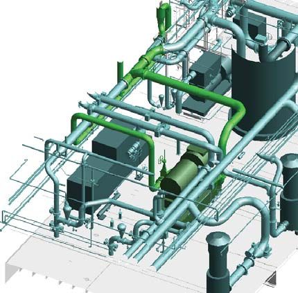
Riser and umbilical analysis
Reference list
This list is not exhaustive

Start   End
year    year      Client            Project title

2010    ongoing   BP                Oselvar riser caisson on Ula

2010    ongoing   Repsol            Montanazo and Lubina, catenary from jacket, 161m

2009    ongoing   Eni Norge         Goliat, 3x pliant wave configurations, 400m from FPSO

2008    2008      Statoil           Troll B, Pliant wave configuration, 325m from semi

2008    2009      BP                Block 31, 2020m carbon fibre reinforcement, 4x lazy wave configs from FPSO

2008    2008      Eni/Nae, Allied   Oyo, lazy wave configuration, 350m from FPSO

2008    2008      Statoil           Morvin, pliant wave configuration, 300m from semi

2008    2008      Statoil           Vega, pliant wave configuration, 370m from semi

2008    2008      Statoil           Gjøa, 2x pliant wave configurations, 370m from semi

2007    2007      Reliance          MA-D6, pliant wave configuration, 1150m from FPSO

2006    2006      Murphy Oil        Kikeh, 2x lazy wave and 2x jumper configurations, 1350m from SPAR/FPSO

2006    2006      ExxonMobil        Saxi Batuque (Kizomba C), 3x lazy wave configurations, 720m from FPSO

2006    2006      Chevron (STAR) Agbami, 4x lazy wave configurations, 1500m from FPSO

2006    2006      ExxonMobil        Marimba North (Kizomba A), lazy wave configuration, 1180m from FPSO

2006    2006      BP                Block 18, lazy wave and jumper configuration, 1310m from FPSO

2004    2004      ExxonMobil        Deepwater power cable (generic), lazy wave configuration, 1524m from FPSO

2004    2004      Total             Rosa, 4x lazy wave configurations, 1350m from FPSO

2003    2003      ExxonMobil        Kizomba B, lazy wave configuration, 1015m from FPSO

2002    2002      ExxonMobil        Kizomba A, lazy wave configuration, 1182m from FPSO

                                                                                            © Aker Solutions 2010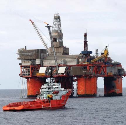
Structural reanalysis
Consistent, predictable and safe

                            An offshore structure is designed for a certain      A structural reanalysis agreement will typically
                            production life and specific operational con-        cover the following aspects:
                            ditions. However, conditions change during
                            operation and incidents occur. That demands          • development and maintenance of structural in-
                            constant attention to safeguard uptime and           place models
                            production flow.                                     • development and maintenance of structural
                                                                                 fatigue and redundancy models
                            We deliver the complete reanalysis package to        • rapid reanalysis of the structures in the event of
                            make sure that your structure stays in produc-       damage
                            tion as long as possible. When you sign a frame      • reanalysis of the structures in the event of signifi-
                            agreement for reanalysis with us, the structural     cant changes to topside weight and/or ballast
                            integrity of your fixed and floating installations   • assessment of the significance of changes in
                            will be handled by some of the most experienced      environmental design criteria
                            reanalysis engineers in the business.                • development and maintenance of a weight moni-
                                                                                 toring system
                            We work on a project basis as well as under          • development and updating of the structural
                            frame agreements. This ensures flexibility for our   inspection strategy and programme
                            customers, since it provides both long- and short-   • assessment of structural inspection results
                            term solutions.                                      • annual summary report on asset integrity

                            Signing a frame agreement with us gives you all      We have in-depth knowledge of prevailing off-
                            the benefits of a stable relationship.               shore standards and regulations, and a broad
                                                                                 base of specialist personnel.

                                                                                 Our structural calculations and analyses are
                                                                                 performed using the leading industry-standard
                                                                                 software packages.

For more information on
our structural reanalysis
capabilities, please
contact

Bergen
Gunnar Bremer,
manager, on
+47 90 85 15 34 or at
gunnar.bremer                                                                      “A stable relationship
@akersolutions.com

Stavanger
                                                                                   leads to better
Eirik Engevik, manager,
on +47 957 45 693 or at                                                            solutions”
eirik.engevik
@akersolutions.com

Visit us at
www.akersolutions.com

                                                                                                              © Aker Solutions 2010
Structural reanalysis
Reference list
This list is not exhaustive

Start   End
year    year    Client         Project title

2008    2009    Talisman       Varg A - Lifetime extension study

2007    2008    StatoilHydro   Gullfaks 2030 - ultimate limit state (ULS) and fatigue limit state (FLS) analyses

2007    2008    StatoilHydro   Troll A - ULS and FLS analyses

2007    2007    StatoilHydro   Statfjord late life, ULS and FLS analyses

2007    2007    StatoilHydro   Veslefrikk B - FLS analyses

2006    2008    StatoilHydro   Crane pedestals - several structural analyses for crane exchange

                                                                                             © Aker Solutions 2010
Structural fire analysis
Challenge previous thinking

                           Optimising passive fire protection (PFP) means    Typical steps during the PFP design process
                           reducing offshore work.                           are:

                           PFP is often extensively used for structures on   • run fire simulation
                           both new and existing offshore installations.     • propose PFP layout
                                                                             • compute temperature and structural response
                           Many reasons exist for minimising the amount      • propose optimal PFP design layout
                           of PFP:
                                                                             Our method takes account of research and devel-
                           • high purchase and installation costs            opment results over recent years, including:
                           • complicates inspection
                           • complicates modifications                       • better knowledge about the behaviour of differ-
                           • substantial maintenance costs                   ent hydrocarbon fires
                           • weight issues.                                  • international standards for the behaviour of ma-
                                                                             terials at high temperatures
                           We provide an analysis method which identifies    • analysis of structures exposed to extreme (ac-
                           and documents safe solutions while reducing the   cidental) loads
                           amount of PFP.                                    • specialised analysis tools

                                                                             Tools include:

                                                                             Kameleon FireEx
                                                                             Fahts
                                                                             Usfos
                                                                             Sesam

Ill. Structural response
to a jet fire

For more information on
our structural fire
analysis capabilities,
please contact Christian
Øverland, manager, on
+47 95 94 96 07 or at
christian.overland
@akersolutions.com                                                                   “Optimise your
Visit us at
www.akersolutions.com                                                                fire protection”

                                                                                                        © Aker Solutions 2010
Structural fire analysis
Reference list
This list is not exhaustive
Start End
year year Client Project title
2010 ongoing Statoil Gullfaks C
2009 ongoing ConocoPhillips Tor platform
2009 2009 Total Usan FPSO flare
2009 2009 StatoilHydro Snøhvit
2008 2009 APL Nexus FPSO
2008 2009 APL APL turret system study
2008 2009 BP Skarv FPSO
2008 2009 BP/SBM SBM Skarv turret
2008 2008 StatoilHydro Troll C LPP
2007 2008 StatoilHydro Gjøa floater
2006 2007 StatoilHydro Snorre A
2006 2007 BP Ula D platform
2005 ongoing BP Ula P platform
© Aker Solutions 2010Structural inspection and maintenance
programme - SIMP™
Extending service intervals on floaters
New oil resources need to be found to meet SIMP™ in brief
the world’s ever increasing demand for energy.
As such discoveries are made in ever deeper • SIMP™ helps to monitor and assess structural
waters, floating exploration and production integrity, including the fatigue capacity of the
facilities become increasingly necessary. structure
• Rigs beyond their design life (FUI>1) normally
Floating facilities such as semi-submersibles need inshore inspection of the hull at 2.5-year in-
and FPSOs are normally designed to clas- tervals (DNV class requirement for harsh environ-
sification society rules and subject to regular ment)
inspections. Introducing our SIMP™ provides • With SIMP™, the renewal survey (RS) interval is
a specific detailed maintenance and inspection maintained at five years
programme for fatigue-prone areas to increase • SIMP™ inspection scope is based on the struc-
structural reliability. tural reliability analysis technique, which
accounts for the effect of inspection, maintenance
Our method is based on solid engineering experi- and fatigue life estimates
ence combined with the use of sophisticated finite • The inspection scope is re-assessed for each
element analyses. The following elements are class period, depending on previous inspection
considered: results
• SIMP™ increases the structural reliability of the
• history of the rig (operations and modifications) rig, and has the potential to reduce costly down-
• inspection history of welds time for the owner
• global analyses and local finite element analyses
of fatigue-sensitive details References
• inspection programme for next class period.
DNV, LR, Odfjell Drilling, Statoil, Fred Olsen
The method is known as SIMP™ (Structural in- Energy/Dolphin, Songa Offshore, Petrofac
spection and maintenance programme).
For more information on
our SIMP™ capabilities,
please contact
Jermund Andreassen,
manager, on
+47 99 29 70 17 or at
“Minimise
jermund.andreassen
@akersolutions.com.
Visit us at
www.akersolutions.com recertification
downtime while
maintaining required
reliability level.”
© Aker Solutions 2010Structural inspection and maintenance
programme - SIMP™
Reference list
Start End
year year Client Project title
2008 2010 Dolphin Drilling Ltd SIMP™ on Borgny Dolphin
2008 2009 Songa Offshore SIMP™ on Songa Dee
2008 2009 Petrofac Ltd. SIMP™ on Northern Producer
2007 2008 Dolphin Drilling Ltd SIMP™ on Borgholm Dolphin
2006 2006 Dolphin AS SIMP™ on Bredford Dolphin
2006 2006 Odfjell Drilling SIMP™ on Deepsea Delta
2005 2005 Odfjell Drilling SIMP™ on Deepsea Bergen
2004 2005 Dolphin Drilling Ltd SIMP™ on Port Reval
2004 2005 Dolphin Drilling Ltd SIMP™ on Borgsten Dolphin
2004 2005 Dolphin Drilling Ltd SIMP™ on Byford Dolphin
2004 2004 Odfjell Drilling SIMP™ on Deepsea Trym
2003 2004 Dolphin AS SIMP™ on Borgland Dolphin
2003 2004 Dolphin AS SIMP™ on Bideford Dolphin
1998 1999 Statoil SIMP™ on Veslefrikk B
© Aker Solutions 2010Inspection and maintenance technology
Technical integrity solutions
We provide technical integrity services for
life-cycle management of structures as well
as mechanical and static process equipment
through four business areas:
• asset integrity management
• advanced NDT inspection
• in-service inspection
• fabrication and weld inspection.
Our focus is on optimising life-cycle maintenance
and reducing inspection costs for offshore oil and
gas operators through:
• total technical integrity management solutions
• development and use of advanced technologies
and methods
• access to extensive knowledge, expertise and
experience.
Areas of expertise:
• project management
• maintenance and inspection analysis
• static and dynamic structural analysis
• QA/QC and NDT inspection
• materials technology
• welding technology
• monitoring technology
For more information on
our inspection and
maintenance technol-
ogy capabilities, please
contact Ronny Øye,
manager, on
+47 93 05 73 67 or at
ronny.oye
@akersolutions.com.
“Find all the defects
Visit us at
and degradations
before they become
www.akersolutions.com
critical”
Photo by Statoil - Rune Johansen
© Aker Solutions 2010Inspection and maintenance technology
Reference list
This list is not exhaustive
Start End
year year Client Project title
Statoil, BP, Shell,
2008 ongoing Various installations - Advanced NDT, Eddy current/RFT tube inspection
Teekay etc.
Tampen - In-service inspection and NDT, Maintenance and inspection
2003 ongoing Statoil
engineering
Statoil, Odfjell
2007 ongoing Various installations - Advanced NDT, Phased array/TOFD
Aker Drilling etc.
2004 ongoing Dong Various installations - Maintenance and inspection engineering
Halten Nordland - In-service inspection and NDT, Maintenance and insp.
2003 ongoing Statoil
engineering
2000 ongoing DNV NDT inspection
Statoil, Shell, Various international installations - Advanced NDT, Vibration and stress
2000 ongoing
Teekay, BP etc. measurement
Statoil, Exxon,
1996 ongoing Various international installations - Advanced NDT, Thermographic inspection
Shell, BP etc.
1995 ongoing Statoil Mongstad - In-service inspection and NDT, maintenance and insp. engineering
1991 ongoing BP Various installations - Maintenance and inspection engineering
2009 2010 Statoil/GDF Gjøa - Maintenance and inspection engineering
2006 2008 Statoil Various installations - Research and development (TAIL, PYRAMID, HOIS2000)
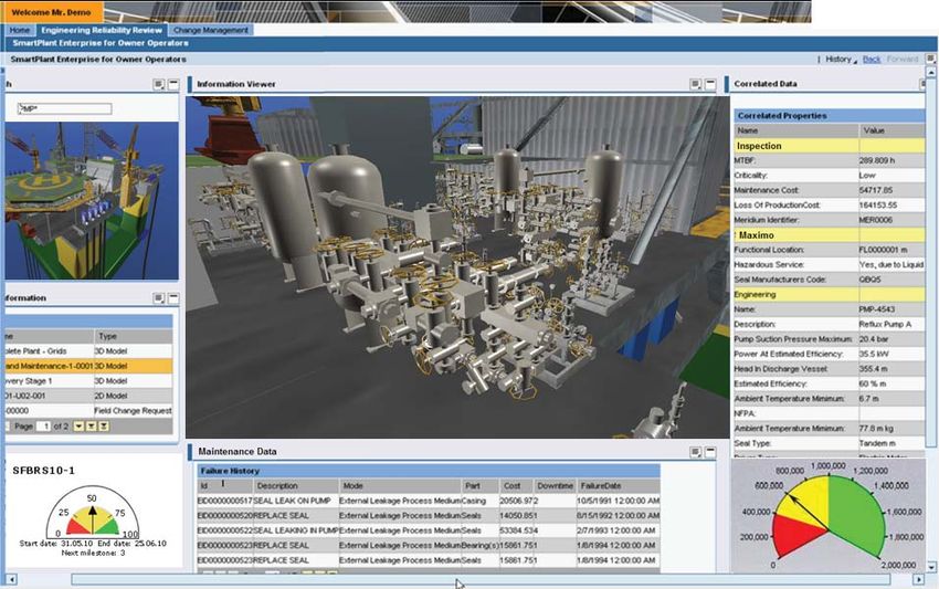
© Aker Solutions 2010Technical integrity management services
(TIMS)
Condition-based maintenance
TIMS is a multidisciplinary service which brings Typical scope of work
together a unique package of expertise and
tools to help you achieve optimum asset per- • Initiation meeting – what’s in it for you?
formance. • CBM study with participants from Tims team in
dialogue with customer
It will improve planning and preparation for the • Narrow-down meeting with decision for further
next generation of integrated operation (IO), and work
supports quicker and better-informed decisions in • Implementation of agreed CBM strategy and
a distributed organisation. This is based on mak- philosophy
ing information available to the different disciplines • Implementation of pilot or demonstrator to assist
throughout the field’s producing life, independent in decision-making and of a people process for a
of location. full Tims roll-out.
A culture change is needed, from asset repair Partnership to provide a complete service
to asset reliability.
• Our own group, with 30 years of experience in
The overall objective is to maximise production, maintenance and modification solutions
reduce downtime and predict degradation. • IBM, utilising its service oriented architecture
(SOA), reference semantic model (RSM) and
To ensure safe, reliable and efficient operation, integrated information framework (IIF) solutions to
effective collaboration between all involved disci- integrate information. Ease the decision-making
plines is crucial. process
• SKF provides comprehensive CBM services for
all rotating equipment
For more information on
our TIMS capabilities,
please contact Jarle
Daae, manager, on
+47 41 29 76 67 or at
jarle.daae
@akersolutions.com.
“From asset repair
Visit us at
www.akersolutions.com
Or you can contact our
partner at IBM, Arild to asset reliability”
Kristensen, manager, on
+47 90 53 25 91 or at
arild.kristensen
@no.ibm.com
Or you can contact
our partner at SKF, Tor
Morten Olsen, manager,
on +47 97 12 34 83 or
at tor.morten.olsen
@skf.com Photo: Ralf Reeger
© Aker Solutions 2010Technical integrity management services
Sample CBM web portal
© Aker Solutions 20103D laser scanning
Remodelling existing structures
We perform laser scanning, establish a master Hardware includes:
grid and offer remodelling/3D solutions for • Getac, fully rugged scanner laptops
offshore installations, land-based power plants • One Leica C10
and modules. The 3D Cad result can be pre- • Three Leica HDS6100
sented in various Cad formats, including the • 21 Leica total stations
industry standard 3D PDMS.
We can also rent two C10 units at short notice.
We enable access to TruView data on our web
portal. Software includes:
• SC4W
Our 3D laser scanning group consists of 40 engi- • Survey Explorer
neers and a number of consultants. This team was • Bentley 3D Microstation
established in 1995 by experienced surveyors, • PipeElements
giving you the benefit of a long and proven track • DgnPdms
record. • Leica Cyclone
• Leica Cloudworx for PDMS
Our goal is to establish a 3D model which is as • Bentley Cloudworx for Microstation
exact as possible by focusing on high quality in • FI XFactor
our scanning and remodelling performance. • NavisWorks
We are at the forefront in utilising the latest hard-
ware and software solutions.
For more information on
our 3D laser scanning
capabilities, please con-
tact Georg Gaard, on
+47 41 68 98 93 or at
georg.gaard
@akersolutions.com.
Visit us at
www.akersolutions.com
“We remodel reality”
© Aker Solutions 20103D laser scanning
Reference list
This list is not exhaustive
Start End
year year Client Project title
2009 ongoing Shell Ormen Lange, scanning and remodelling of various compressors and skids
2009 2009 Statoil Brage, wellhead area scanned and remodelled
2008 2008 Statoil Grane, scanning and remodelling of modules
Rosenberg
2008 2008 Ekofisk C (ConocoPhillips), jacket and bridge landings scanned and remodelled
verft
2008 2008 Shell Draugen GBS, laser scanning and ongoing remodelling of selected GBS levels
2008 2008 Statoil Oseberg B, laser scanning and remodelling of drill floor and the pump room
2007 ongoing BP Valhall, Ula, Tambar, Flank N&S
2007 2008 Statoil Troll B&C, areas scanned and remodelled for LPP project
Eldfisk A&B, established complete PDMS 3D model based on scanning and
2006 2007 ConocoPhillips
remodelling
2006 2006 Statoil Snorre A, minor area scanned and remodelled
Ekofisk bridge landing and 2/4-M jacket, scanned to verify position, long range
2005 2005 ConocoPhillips
scan
Statfjord late life project; large number of areas have been scanned and
2005 ongoing Statoil
remodelled
© Aker Solutions 2010Advanced hydrodynamic analysis
Solving complex problems in a
demanding marine environment
The world’s growing demand for energy contin- So we can help you whether your floating produc-
ues to push companies further offshore into tion system faces increased wave-heights, rising
increasingly challenging waters, such as deep- topside weight is causing stability concerns, or
water or Arctic (very shallow). you need to deal with other challenges to your
marine structure.
Floating exploration and production facilities
need motion, mooring and stability analyses Typical services include:
to determine safe operating conditions. The
structures supporting the drilling and produc- • advanced flow simulations (CFD)
tion equipment need accurate prediction of • air gap analysis
wave loads to determine strength and fatigue • marine operations simulations
capacity, and operators need predictable and • motion analysis
reliable performance. • mooring analysis
• stability analysis
We have an experienced and well-established • wave-impact analysis (WISR).
hydrodynamics team. With a combination of
experience gained from projects all over the globe, Software typically used includes:
great theoretical knowledge and continuous learn-
ing through such means as joint industry projects, • AutoHydro
our staff have the background and the latest tools • Comflow
to provide the answers and solutions our clients • DeepC
need. • Flow-3D
• HydroD
Our personnel are experienced in both evaluation • Mimosa
and modification of existing structures as well as • Simo
the development and evaluation of new concepts. • Wadam
We help our clients to find and document optimum
solutions through advanced analysis, knowledge
of rules and regulations, and use of our know-how.
For more information on
our advanced hydro-
dynamics capabilities,
please contact
Lars Rønning, manager,
on +47 97 52 63 45 or
at lars.ronning
@akersolutions.com
“Understand how
Visit us at
www.akersolutions.com
your structure
responds in a
marine environment”
© Aker Solutions 2010Advanced hydrodynamic analysis
Reference list
This list is not exhaustive
Start End
year year Client Project title
2008 ongoing Statoil Veslefrikk B, dynamic mooring analysis
2010 2010 Odfjell Deepsea Atlantic, hydrodynamic model
2009 2010 Statoil Visund, simplified stability analysis
2009 2010 Statoil Grane, conductor/guide hydrodynamic interaction
2009 2009 BP Valhall DP, wave-in-deck analysis
2008 2009 ConocoPhillips Eldfisk A and B, wave-in-deck analysis
2008 2008 ConocoPhillips Mooring operability study for Arctic areas
2008 2008 Dolphin Drilling Bredford Dolphin, airgap analysis
2008 2008 Statoil Veslefrikk B, stability analysis
2008 2008 Odfjell Deepsea Trym, inclining experiment
2008 2008 Odfjell Deepsea Bergen, motion analysis
2007 2008 ConocoPhillips Tor, wave-in-deck analysis
2004 2005 Total Norge Frigg DP2, hydrostatic and towing
2004 2005 Total Norge Frigg QP, hydrostatic and towing
© Aker Solutions 2010Weight and stability services
Effects of changes to offshore
structures in the operation phase
In order to document the structural integrity of We provide an in-house presence with the dis-
offshore structures, updated information about ciplines involved, such as weight and stability,
weight and centre of gravity as well as mar- structural reanalysis, hydrostatics and hydrody-
gins must be available. This is required both namic expertise, and cost control.
by Norwegian government regulations (PSA
activity regulations, section 23, and framework A focus on weight control at management level
HSE regulations, section 28) and as the basis leads to better quality of deliverables, ensuring
for customer decisions on new development that the as-is database is more accurate. That in
concepts. turn enhances safety.
Our weight and stability services can be pur- Typical scope of work:
chased stand-alone, as a third-party consultancy
or as part of a frame agreement. • provide updated information of weight and cen-
tre of gravity of lifted objects
Working closely with our structural reanalysis • verification of weight databases
group, our experts on stability and floaters, and • continuous updating of weight databases with
other departments in our special technology ser- changes from maintenance and modification con-
vices team, some 25 databases are maintained for tracts and other projects
installations on the NCS. • update of lightship weight as input to stability
• import of standalone projects to weight data-
• continuous improvement of procedures and bases
work instructions • input to cost control related to compensation
• continuous focus on the importance of weight models
control in projects.
Tools include:
• Mon
• Client computerised maintenance management
system – CMMS (SAP, Workmate, etc)
• Aker Solutions operating system (PEM™)
For more information on
our weight control
capabilities, please
contact Rune Ellefsen,
manager, on
+47 90 16 52 14 or at
rune.ellefsen
“We manage
@akersolutions.com.
weight changes on
operational offshore
Visit us at
www.akersolutions.com
installations until
removal”
© Aker Solutions 2010Weight and stability services
Reference list
This list is not exhaustive
Start End
year year Client Project title
2010 ongoing Statoil Norne Topside Mod.
2010 ongoing Statoil Linnorm to Njord Concept study
2008 ongoing Statoil GFA/GFB Cement
2009 2010 Statoil Kristin LPP FEED
2007 2010 Statoil Troll C LPP
2009 2009 Statoil Njord
2009 2009 Statoil Alve tie-in to Norne
2007 2008 Statoil VFB 2020
We maintain and update weight databases for the following installations
Client Installations
BP Valhall QP, DP, PCP, WP, IP
Valhall flank south, Valhall flank north
Hod
Ula Q, D, P
Tambar
Statoil Gullfaks A, B, C
Troll A, B, C
Brage
Veslefrikk A, B
© Aker Solutions 2010Asset management
Providing decision support
Our asset management group provides spe- Staffing analyses
cialist services suited for operators of produc- Benchmarking maintenance performance, the
tion plants. We aim to provide operation and number of inherent maintenance work-hours,
maintenance support services for land-based staffing level per trade, Opex and life-cycle operat-
and offshore facilities. ing cost for:
• new plants - especially during the design phase
The team embraces a mix of personnel, ranging when configuration changes are still possible to
from experienced engineers with a number of reduce operating and/or total life-cycle costs
years of operational involvement to young profes- • established plants - where the requirement is
sionals with the latest theoretical knowledge. to identify excessive operating and maintenance
costs
Maintenance strategy • design changes – where the requirement is to
Our group provide advisory services for devel- establish the effect of changes on work-hours and
oping suitable maintenance strategies to fit the Opex.
operator’s operational philosophies and business
goals. Vital elements include handling integrated Maintainability evaluations
operation and condition-based maintenance. Multi-disciplinary evaluations of maintenance
activities for equipment will be applied to ensure
Maintenance engineering easy change-out at global, regional and local
This includes various analyses, such as critical- scales. Selecting maintenance-friendly equipment/
ity, risk-based inspection (RBI) and RSM, and packages is essential for streamlined and efficient
the development of inspection and maintenance maintenance execution.
programmes. A tailormade tool named Pyramid is
normally utilised. Our material handling philosophies are in line with
governing standards and regulations, and are
Production availability analysis aligned with company operational philosophy and
The Miriam Regina simulation tool is used for best industry practice.
production availability analyses to achieve and
maintain high production regularity on oil and gas
fields, maximising the utilisation of producing as-
sets and contributing to company profits.
For more information on
our asset management
capabilities, please
contact Tom Svennevig,
“Providing decision
manager, on
+47 46 40 22 48 or at
support for manag-
ers of oil and gas
tom.svennevig
@akersolutions.com.
Visit us at
www.akersolutions.com fields utilising Aker
Solutions knowl-
edge, resources
and state of the art
tools”
© Aker Solutions 2010Asset management
Reference list
This list is not exhaustive
Start End
year year Client Project title
2010 ongoing Statoil OREDA data collection
2009 2010 Det norske Draupne staffing study
2009 2010 Statoil Snorre B waste heat recovery robustness study - availability analysis
2009 2009 Statoil Gudrun tie-in to Sleipner East - availability analysis, material handling philosophy
2009 2009 Shell Ormen Lange subsea compression test site
2008 2010 ConocoPhillips Greater Ekofisk area development FEED
© Aker Solutions 2010Flow assurance
Reliable and safe fluid transportation
Flow assurance studies are carried out to per- The scope of services embraces transient
mit reliable and safe fluid transport from wells multiphase flow studies of pipelines, flowlines,
to processing facilities. Such studies entail risers and wells, including:
analysis of thermal, hydraulic and produc-
tion issues arising from design, operation and • pipe sizing
maintenance of the total systems over the life • slugging studies
cycle of the field. • thermal studies
• artificial lift studies
Multiphase and dynamic simulations are per- • pigging simulations
formed using advanced software tools in: • hydrate, wax, scale and corrosion control
• blowdown studies
• the design phases • troubleshooting on operational issues
• the operational phases (troubleshooting) • technical audits and consultancy services.
• late life with changes in compositions and flow
rates Software tools include:
The flow assurance team in Norway consists of • Olga – for dynamic simulation of multiphase
personnel in Oslo, Stavanger, Bergen and Kristian- pipelines
sund, but our international network can be utilised • Aspentech Hysis Dynamics –- for dynamic simu-
if required. lation of topside processing facilities
• PVT Sim – for generating pressure, volume and
temperature (PVT) data
For more information on
our flow assurance
capabilities, please
contact
Stavanger
Tore K. Berge,
manager on
“Flow assurance is
+47 51 93 73 23 or at
tore.k.berge
@akersolutions.com
Visit us at critical in every field
development”
www.akersolutions.com
© Aker Solutions 2010Flow assurance
Reference list
This list is not exhaustive
Start End
year year Client Project title
2010 2010 BP / DONG Oselvar - Ula pipeline blowdown
2010 2010 ConocoPhillips Greater Ekofisk - 2/7N-2/7S wellstream transfer
2010 2010 Gassco Flow assurance support
2010 2010 ConocoPhillips Greater Ekofisk Area Development - Flow simulations in topside flowline
Tampen V&M: Snorre B - Overpressure protection of inlet configuration from
2007 2010 Statoil
high pressure in subsea wellstream production flowlines
Greater Ekofisk Area Development - Choke collapse evaluations on EldA and
2009 2010 ConocoPhillips
EldS (new)
Various minor projects regarding temperature estimation in connection with gas
2009 2010 BP
lifted wells on Valhall
2009 2010 Statoil Gudrun Gas Segment Blowdown
2006 2010 BP Skarv Flow Assurance
2008 2009 ConocoPhillips Greater Ekofisk Area Development - Existing pipelines study
2009 2009 Dong Oselvar Flow assurance verification
2008 2009 ConocoPhillips Greater Ekofisk - 2/7N-2/7S wellstream transfer
2008 2008 Norske Shell Hasselmus, well and pipeline parametric study
2008 2008 Norske Shell Hasselmus, pipeline blowdown and inhibition
2008 2008 BP Valhall Flanks Gas Lift, Production Pipelines
2008 2008 BP Valhall Flanks Gas Lift, Annulus Blowdown
2008 2008 BP Valhall Flanks Gas Lift, Gas Lift Pipelines
2008 2008 Burgundy Malampaya oil Rim Flow Assurance evaluation
2007 2008 Statoil Veslefrikk 2020 - Choke collapse
2007 2008 Norske Shell Hasselmus reservoir tie-back to Draugen
2007 2008 ConocoPhillips Slugging evaluations in multiphase pipeline
2006 2008 BP Valhall Flanks Gas Lift, Production Pipelines
2007 2007 Lundin Peik Flow Assurance
2006 2007 Statoil Tampen M&M: Statfjord C - satellite production debottlenecking
© Aker Solutions 2010Dynamic process simulations
Dynamic process simulations analyse the re- Typical scope of work
sponse in variables like pressure, temperature
and flow rate during transients that could be • Design of new systems
caused by: • Verification of systems
• Analyses of new operating conditions
• Variations in the boundaries – rate, • Analyses for new rules and regulations
temperature, pressure and composition • Trouble shooting on operational issues
• Fault situations – trips and leakage • Technical audits and Consultancy services
• Operational problems
• Procedures – start-ups / shutdowns
Software tools
The simulations may contribute to process design
and verify design or result in redesign of: • OLGA - for dynamic simulation of multiphase
pipelines
• Compression systems • Aspentech Hysys Dynamics - for dynamic
• Sea and firewater systems simulation of Topside processing facilities
• Water injection systems • PVT sim - for generation of PVT data
• Control strategies • Pipenet transient – for transient analyses of
• Parameter tuning flow in pipeline networks
• Procedures (Start-up, shutdown and trip) • ASSETT – for dynamic simulation of topside
• Choke collapse scenarios processing facilities
• Safety systems e.g. flare system
Dynamic process simulations are performed using
advanced software tools and are performed both
in the design phases as well as in the operational
phases.
For more information on
our dynamic process
simulation capabilities,
please contact
Stavanger
Tore K. Berge, 900000 400
manager, on
+47 51 93 73 23 or at 800000 350
tore.k.berge
@akersolutions.com 700000
300
Bergen 600000
Kim Henry Kristiansen,
“The real world
250
manager, on
500000
Trykk
Flow
+47 55 22 48 53 or at
200
kim.henry.kristiansen
@akersolutions.com 400000
150
is dynamic”
Visit us at 300000
www.akersolutions.com 100
200000
100000 50
0 0
4 4.5 5 5.5 6 6.5 7
Tid [s]
© Aker Solutions 2010Dynamic process simulations
Reference list
This list is not exhaustive
Start End
year year Client Project title
2010 2010 Statoil Brage - Pressure Protection of Inlet Arrangement
2010 2010 BP / DONG Oselvar - Ula pipeline blow down
Greater Ekofisk Area Development - Choke collapse evaluations on EldA and
2009 2010 ConocoPhillips
EldS (new)
2009 2010 Statoil Troll B Low Pressure Production
Various minor projects regarding temperature estimation in connection with gas
2009 2010 BP
lifted wells on Valhall
2009 2010 Statoil Gudrun Gas Segment Blowdown
Tampen V&M: Snorre B - Overpressure protection of inlet configuration from
2007 2010 Statoil
high pressure in subsea wellstream production flowlines
2008 2009 ConocoPhillips Greater Ekofisk development - Existing pipelines and choke failures
2006 2009 BP Skarv Firewater system transient analysis
2008 2008 BP Ula Power Upgrade - Capacity evaluation for the fuel gas scrubber
2008 2008 BP Valhall Flanke Gas Lift - Minimum temperature calculations in vent system.
2008 2008 BP Skarv Inlet Valve maloperation
2008 2008 BP Skarv Seawater system transient analysis
2007 2008 Statoil Veslefrikk 2020 - Choke collaps
2007 2008 Statoil Statfjord Late Life - Dynamic compression simulations
2006 2008 BP Valhall Flanks Gas Lift, Production Pipelines
2007 2007 Statoil Gjøa Firewater system transient analysis
2006 2007 Statoil Tampen V&M: Statfjord C - Satellite production debottlenecking
© Aker Solutions 2010Hazard and operability analysis (HAZOP)
Identify safety and operational issues
HAZOP analysis is a reputable and well proven HAZOP highlights include:
method for identifying safety and operational • systematic examination
issues related to the design, operation and • multidisciplinary study
maintenance of a system. • utilisation of operational experience
• safety as well as operational evaluations
Essentially, a HAZOP analysis provides a full • may indicate solutions to the identified problems
description of a process and systematically ques- • considers operational procedures
tions every part of it to establish how deviations • human errors
from the design intention might arise. This is done • led by an independent person
in a formal and objective way, based on pre- • results are recorded.
defined guide words.
We have long experience of HAZOP, and house a
Once identified, deviations and their consequenc- team of experienced HAZOP facilitators who are
es are assessed to see whether they might have a able to help clients organise and perform such
negative effect on safe and efficient plant opera- analyses. Staff in Stavanger can be supplemented
tion. This technique ensures a systematic evalua- by experienced HAZOP facilitators at our offices in
tion to identify potential problems/hazards. Oslo and Bergen.
For more information on
our HAZOP capabilities,
please contact
Stavanger
Carsten Ehrhorn,
manager on
+47 51 85 23 39 or at
“Providing the
carsten.ehrhorn
@akersolutions.com
Bergen
Brynjulf Rune Berentsen knowledge to
facilitate HAZOPs”
on +47 55 22 30 19
or at
brynjulf.rune.berentsen
@akersolutions.com
Visit us at
www.akersolutions.com
© Aker Solutions 2010Hazard and operability analysis (HAZOP)
Reference list
This list is not exhaustive
Start
year Client Project title
2010 Shell Ormen Lange
2010 Statoil Gas lift
2010 Statoil Crossover Vigdis WI pump to jet water
2010 Statoil Snorre, dosing of chlorine dioxide
2009 Shell Draugen (multiple)
2009 Shell Ormen Lange (multiple)
2009 ConocoPhillips GEAD (FEED)
2009 BP Valhall pilot PW (FEED)
2009 Talisman Gyda gas lift (FEED)
2009 Statoil Sleipner, Gudrun tie-in FEED
2009 BP Oselvar tie-in
2009 BP Produced water treatment
2009 Statoil Statfjord late life (multiple)
2009 BP HOD booster pump
2009 Statoil Sleipner, Alfa Vest (FEED)
2009 Talisman Gyda gas lift compressor package, LMF Vienna
2009 BP Valhall Flanke gas lift
© Aker Solutions 2010Safety integrity level (SIL) analysis
Functional safety
The use of instrumented systems in safety We can provide assistance with all aspects of
applications is increasing. The IEC 61508 IEC 61508, including:
standard is widely used by industries – such as • developing project specific methodology to
oil and gas, process, transport and aviation – incorporate IEC 61508/61511 in a project scope
which need highly reliable safety systems. We of work
have incorporated IEC 61511 in our procedures • developing SIL requirements based on risk as-
and our project execution model (PEM) to sessments
achieve full compliance with functional safety • developing safety requirement specifications
principles as specified in IEC standards. (SRS documents)
• participating in the design process for safety
In order to determine the behaviour of an instru- systems to meet integrity requirements and the
mented safety system, the design of its hardware SIL
and software needs to be fully assessed. IEC • calculating the probability of failure on demand
61508 is the international standard for electrical, (PFD) to verify the SIL
electronic and programmable electronic safety- • conducting a functional safety assessment,
related systems. It sets out requirements for third-party verification
ensuring that systems are designed, implemented, • implementing and following-up in the operational
operated and maintained to provide the required phase
safety integrity level (SIL). Four SILs are defined in
accordance with the risks involved in the system
application, with SIL 4 being used for the highest
risks.
Guideline 070 from the Norwegian Oil Industry
Association (OLF) is relevant to the NCS and refer-
enced in the PSA regulations. Our procedures and
PEM comply with OLF GL 070.
For more information on
our SIL analysis capa-
bilities, please contact
Ivar Skjeldal on
+47 4006 9580 or at
ivar.skjeldal
@akersolutions.com
Visit us at
www.akersolutions.com
“Achieving reliable
safety functions
with high integrity”
© Aker Solutions 2010Safety integrity level (SIL) analysis
Reference list
This list is not exhaustive
Start End
year year Client Project title
2010 2010 Shell Draugen - Produced water reinjection – Instrumented protective function review
Kristin LPP FSA – 3rd party review of SIL analysis and SRS development
2010 2010 Statoil
performed in Bergen
Ula V&M, Valhall V&M: Several LOPAs, SRS, Valhall PWRI: LOPA, SRS, IEC
2009 2010 BP
61508/61511 compliance, Valhall Flank Gas Lift: LOPA, SRS
Oseberg drilling upgrade project – SIL allocation, Safety requirement
2009 2010 Statoil
specification, vendor follow-up
Greater Ekofisk area – SIL methodology, SIL allocation, SIL calculations, SRS
2008 2010 ConocoPhillips
development
2005 2008 Statoil Statfjord late life project – SIL methodology, SIL allocation, SRS development
Ula gas upgrade – SIL calculations, SRS development, Blane tie-in – SIL
2005 2006 BP
calculations, SRS development
SFA/B/C overpressure protection system – Design development, SIL risk
2004 2007 Statoil
analysis, SRS
Snorre A integrated over-pressure protection system – SIL calculations, SRS
2004 2005 Statoil
development
Ekofisk 2/4 M wellhead and processing platform – SIS lifecycle activities: SIS
2003 2005 ConocoPhillips methodology, hazard and risk analysis, SIL allocation, SRS development, SIL
calculations
2001 2002 BP SIL analysis Valhall injection platform
© Aker Solutions 2010You can also read