TECNICHE DI RADIOTERAPIA AL SENO CON RAGGI X MONOCROMATICI - G. Mettivier Medical Physics Research Laboratory, Dip. Fisica 'Ettore Pancini', UNINA ...
←
→
Page content transcription
If your browser does not render page correctly, please read the page content below
TECNICHE DI RADIOTERAPIA AL SENO
CON RAGGI X MONOCROMATICI
G. Mettivier
Medical Physics Research Laboratory, Dip. Fisica ‘Ettore Pancini’, UNINA
SR T
  3
Synchrotron Radiation Rotational RadioTherapy
breast cancer
(INFN project – 2018/2020)

G. Mettivier
AIM OF PROJECT

To propose and investigate an innovative therapeutic approach for breast
cancer therapy which combines kilovoltage external beam rotational
radiotherapy using synchrotron radiation, the use of contrast and
radiosensitizing agents, image guidance via pre-treatment and within-
treatment computed tomography scans for precise tumor localization and
patient repositioning, showing its potential with respect to currently available
conventional and experimental radiotherapy techniques for breast cancer.
BRIEF HISTORY

        X Ray tube                        Syncrotron Source

2010   2011   2012   2013   2014   2015   2016   2017   2018   2019   2020   2021   4
                                      YEAR
BREAST CT

J. Boone U.C. Davis Medical Center
BRIEF HISTORY

        X Ray tube                        Syncrotron Source

2010   2011   2012   2013   2014   2015   2016   2017   2018   2019   2020   2021   6
                                      YEAR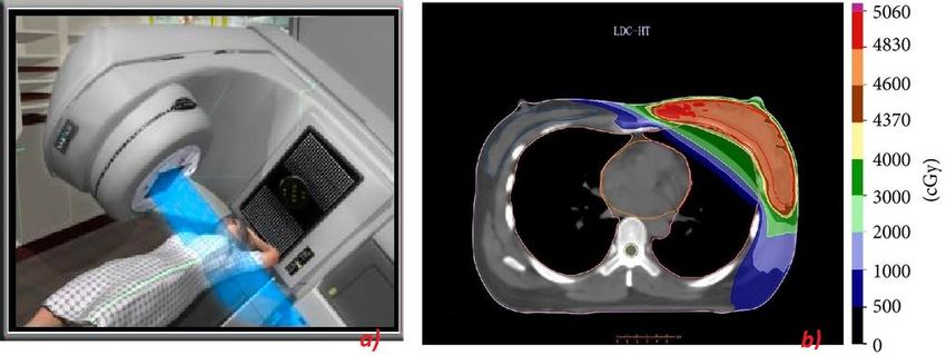
BREAST CT
SYNCHROTRON
RADIOTHERAPY
2016-2017
• Marzo 2015: MASR Conference
• Dicembre 2015: Sottomissione proposal ad ESRF ed AS (accettati)
• Aprile 2016: Lettera di intenti Australian Synchrotron
• Giugno 2016: Lettera di intenti ESRF
• Giugno 2016: Turno di misure presso AS
• Luglio 2016: Turno di misure presso ESRF
• Settembre 2016: Oral contribution ad ECMP
• Luglio 2017: Invito dal Canadian Light Source per proposal congiunto (2 anni)
• Agosto 2017: turno di misure presso AS
• Di Lillo et al., Towards breast cancer rotational radiotheraphy with synchrotron radiation , in
stampa su EJMP-Physica Medica
• Di Lillo et al, Synchrotron radiation external beam rotational radiotherapy of breast cancer: proof
of principle, sottomesso a JSR
• Di Lillo et al, Monte Carlo and Analytical simulations of dose distribution in Synchrotron radiation
rotational radiotherapy of breast cancer: an experimental phantom study , contributo ad MCMA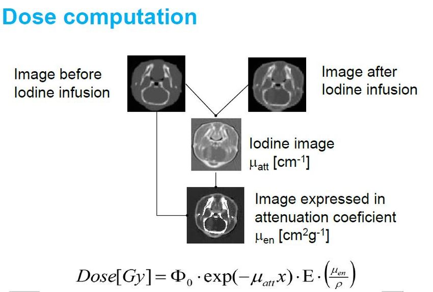
BREAST CT
SYNCHROTRON IRRADIATION
             TECHNIQUES
SYNCHROTRON RADIOTHERAPY
ROTATIONAL RADIOTHERAPY
                                                                                                            W/ ORTHOVOLTAGE X-RAY TUBE
                                         1. Quando il fascio è stretto (1 cm) la dose al bordo è meno del
                                            10% di quella al centro.
                                         2. Quando il fantoccio è totalmente irraggiato (14 cm) il massimo
                                            della dose è al bordo ed il profilo è a forma di coppa

                                                        Percentuale della dose massima
                                                                                         100       14 cm                              7 cm

                                                                                         80

                                                                                         60

                                                                                         40
                                                                                                   POLIETILENE
                                                                                         20                                    1 cm

•   Energia: 178 keV
                                                                                          0
•   Dimensioni fantoccio: 14 cm diametro 9 cm altezza                                          0      20      40    60    80   100      120
•   Materiale: polietilene
•   Collimazioni fascio: 1, 7, 14 cm in direzione x                                                        Posizione orizzontale (mm)
OBIETTIVI • Applicazione di questa tecnica al breast tumor • Ottimizzazione energia e geometria per sparing skin effect • Confronto con la tecnica tradizionale
DOSE
ENHANCEMENT
EFFECT
DOSE ENHANCEMENT
                                                           EFFECT
• Radiation dose enhancement in tumors with iodine, Mello et al., Med. Phys. 10, 75 (1983)
• Calculation of radiation dose enhancement factors for dose enhancement therapy of
  brain tumors, Solberg et al., Phys. Med. Biol. 37, 439-443, (1992)
SYNCHROTRON SOURCE FOR
CT THERAPYOBIETTIVI • Studio del mezzo (nanoparticelle?) e sua concentrazione per dose enhancement effect • Misura dell’effetto biologico • Confronto con la tecnica tradizionale • Phase contrast imaging con mezzo contrasto
DOSIMETRY
DOSIMETRIA
DOSE COMPUTATION
OBIETTIVI

• Applicazione metodi MC per valutazione dose
• Misura dell’effetto biologico
ASPETTANDO SR3T
         (2018)
2016-2017
• Giugno 2016: Turno di misure presso AS
• Luglio 2016: Turno di misure presso ESRF
• Settembre 2016: Oral contribution ad ECMP
• Luglio 2017: Turno di misure presso AS
• Marzo 2018: Turno di misure presso ESRF
• Giugno 2018: turno di misure presso Canadian Light Source
• Di Lillo et al., Towards breast cancer rotational radiotheraphy with synchrotron radiation , in
stampa su EJMP-Physica Medica
• Di Lillo et al, Synchrotron radiation external beam rotational radiotherapy of breast cancer: proof
of principle, sottomesso a JSR
• Di Lillo et al, Monte Carlo and Analytical simulations of dose distribution in Synchrotron radiation
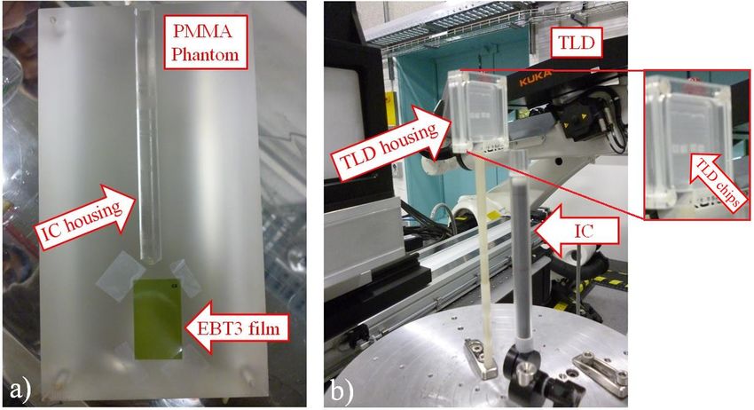
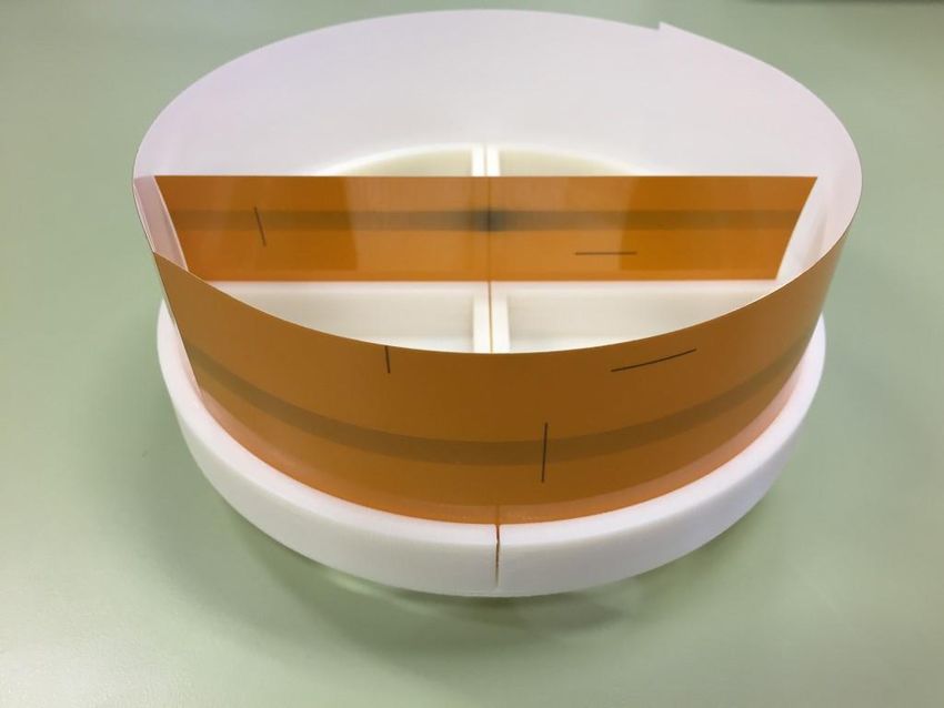
rotational radiotherapy of breast cancer: an experimental phantom study , contributo ad MCMAPRIME MISURE Photo of the midplane face of the two halves cylindrical PMMA phantom containing a cavity for the ionization chamber and with the EBT3 film in place (a); Setup for TLD irradiation (b): four TLD chips inserted in the PMMA housing and 100-mm pencil ionization chamber (IC) placed along the vertical direction. The inset shows the four chips in place in the housing.
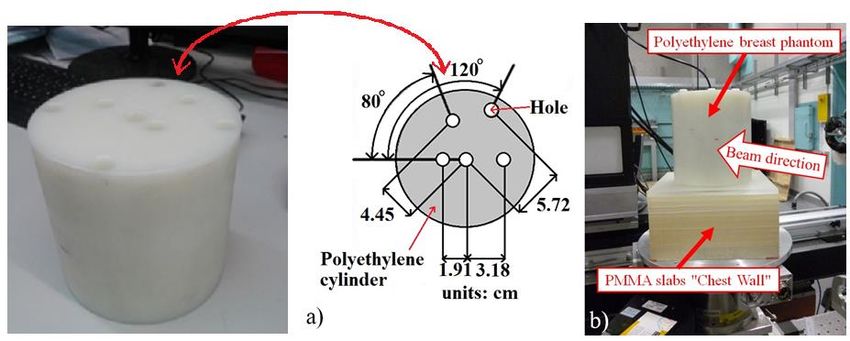
PRIME MISURE

Photo and scheme of the polyethylene cylindrical phantom with five cylindrical holes at various radial
distances for hosting a 100-mm long ion chamber (a). Experimental setup for radial dose profile
measurement, in this image the IC is positioned in the central hole of the phantom (b).
PRIME MISURE
                                                         120
                                                                      60 keV

                        Percentage of central dose (%)
                                                         100
                                                                                                     15 cm
                                                          80
                                                                                             7 cm
                                                          60                       4 cm

                                                          40
                                                               100-mm pencil chamber
                                                               beam height: 8 mm
                                                          20                                1.5 cm
                                                               14-cm diameter PE cylinder

                                                               0       1      2        3      4        5     6
                                                           Distance from the axis of the cylindrical phantom (cm)

Comparison between the measured (symbols) and simulated (lines) relative air kerma in a 14-cm diameter
polyethylene cylindrical phantom for beam width of 1.5, 4, 7 and 15 cm. For the MC simulation, the dose
distribution was evaluated by integrating the dose along 100 mm in the direction of the cylinder axis.
PRIME MISURE
29PRIME MISURE
Percentage of maximum dose
100 60 keV
Experimental
80 Simulated
60
40
20
0 20 40 60 80 100
a) Position along the line (mm)
Dose distributions (a) evaluated with radiochromic film EBT3 at midplane in a 14-cm diameter PMMA
phantom and (b) surface plot of percentage of maximum dose: two off-center foci. The dose distribution
was obtained with two full rotations of the phantom with displaced axis of rotation and different target
doses.SPIRAL MICRO-BEAM RADIATION
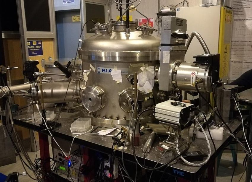
THERAPYPRIN 2015: CLINICALY COMPATIBLE TOOL FOR
ADVANCED TRANSLATIONAL RESEARCH WITH
ULTRASHORT AND ULTRAINTENSE X-RAY PULSES
LASER
Tungsten sample
target
e- beam Magnetic Bremsstranhlung
dipole x-rayMARIX
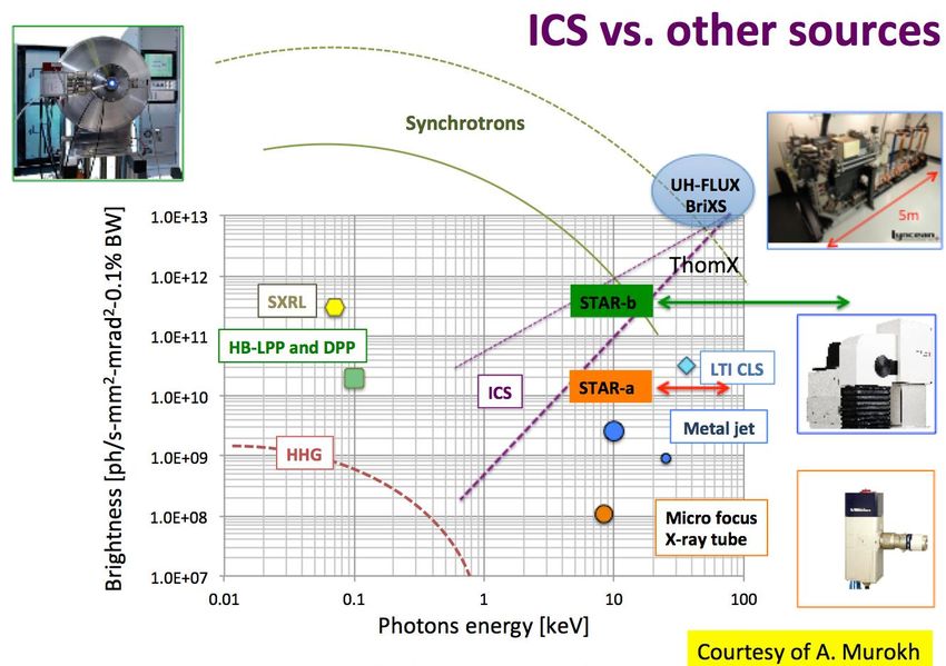
Caratteristiche sorgente
Compton mono-chromatic X-ray beam
Energy: 30 -150 keV
Flux: 1013 photons/s
Phase X-Ray photon X-ray flux
energy (keV) (ph/s)
0 20-90 1011
1 20-90 1012 4 years
2 20-200 1015 2-3 years
Vantaggi
Compact source
Disponibilità di una sorgente
Da Studiare
Fascio divergente
dosimetriaMEDICAL PHYSICS RESEARCH
LABORATORY
Prof. Paolo Russo Prof. Giovanni Mettivier
Professore Ordinario Ricercatore
Coordinatore gruppo V – INFN Napoli
Dr Antonio Sarno Dr Francesca Di Lillo
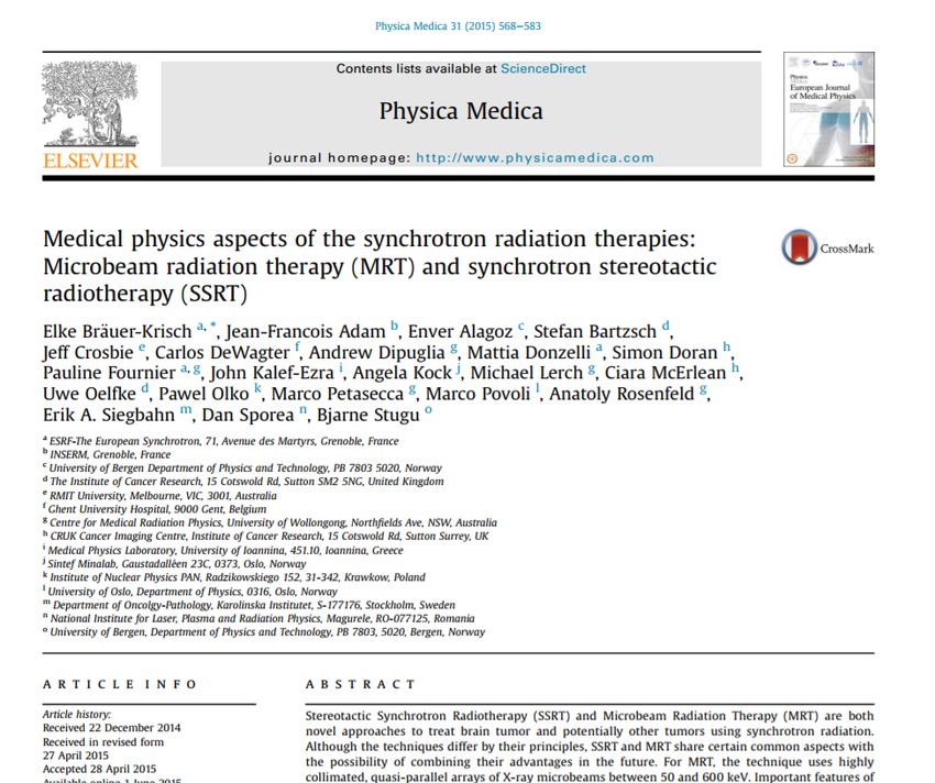
INFN Post Doc Dottoranda 34RADIOTERAPIA CONVENZIONALE
a) Utilizzo di acceleratori lineari al
megavoltaggio (LINAC) e 2 fasci
incidenti lateralmente nel seno
b) Distribuzione di dose risultante e
problematica legata allo “skin
sparing” ed alla salvaguardia degli
altri organi come il cuore (la attuale
EBRT deposita sulla pelle fino al 40%
della dose al tumore ≈ 20 Gy)You can also read