The Case for the 'Do Nothing' Solution for two Heritage-Listed Brick
←
→
Page content transcription
If your browser does not render page correctly, please read the page content below
The Case for the ‘Do Nothing’ Solution for two Heritage-Listed Brick
            Lined Tunnels Impacted by Motorway Construction Above

                                            Noble1, Kingsland2
                 1 Andrew Noble, Technical Executive, Hydropower & Tunnels, WSP Australia
                                       Andrew.Noble@wsp.com
                    2 Robert Kingsland, Technical Executive, Geotechnics, WSP Australia
                                      Robert.Kingsland@wsp.com

ABSTRACT

This paper describes the process taken to arrive at the ‘do nothing’ solution for the structural
assessment of two heritage listed brick lined tunnels that were to be subjected to construction
induced loadings during the excavations of large cuttings for an adjacent expressway.
       The Hunter Expressway Alliance (HEA) designed and constructed a 12.9 km length stretch of the
Hunter Expressway in New South Wales (NSW), Australia. The HEA alliance team comprised Roads and
Traffic Authority, NSW (now Roads and Maritime Services, NSW), Thiess (now CPB), Parsons
Brinckerhoff (now WSP) and Hyder Consulting (now Arcadis). Work involved construction of dual lane,
dual carriageway motorway across a green field site. The expressway passes close to two existing
heritage-listed brick-lined abandoned rail tunnels known as Tunnel 134 and Tunnel 139. Both tunnels
form part of the Richmond Vale Rail Line, which is now disused. Tunnel 134 is 160m in length and
Tunnel 139 is 372m in length, and they were constructed around 1904.
       This paper presents the findings of investigations and structural assessment for the possibility
of construction triggered ground loading from the adjacent excavation works for two major cuttings
for the expressway works, either as a consequence of ground unloading in the case of one cutting
directly above Tunnel 134, or vibrations induced by construction plant and blasting adjacent to
Tunnel 139. The results of this investigation were used to assess the structural capacity of the brick
linings.
       The HEA was mandated to preserve the integrity of the tunnels and to not cause damage. The
assessment of the tunnel linings was undertaken following a risk-based approach and with declaration
of the potential impacts to the various stakeholders. As such, a range of options were explored that
included a ‘no-intervention’ approach. The likely presence of the gap or cavity between the lining and
the rock was acknowledged to have a significant effect on the behaviour of the brick lining in response
to potential induced ground loading and ground borne vibrations.
      A balance was struck between minimising the amount of intrusive testing to preserve the
heritage aspects, while gathering sufficient factual information to support the structural assessments.
A series of small and large diameter drilled cores were taken from the linings to investigate the
parameters of the multi-layered lining and a programme of surveillance and monitoring of vibrations
and displacements was put in place, adopting minimal intrusion for heritage preservation.
       The outcome for the asset owner (Roads and Maritime Services), and the HEA, was that the
assessment demonstrated that no supports were required as the linings could adequately withstand
the induced loadings. This outcome was valuable in terms of retention of the heritage listed asset and
also from a cost perspective.
      Key Words: Heritage, Blasting, Brick-linings, Vibration, Structural assessment.
1.   INTRODUCTION

The Hunter Expressway Alliance (HEA) designed and constructed the 12.9 km of the Hunter
Expressway located 140 km north of Sydney, between the M1 Motorway/Newcastle Link Road
interchange to south of the new Kurri Kurri interchange. Work involved construction of dual lane, dual
carriageways across a green field site. The Expressway was opened to the public in 2013.
      The Expressway passes close to two existing heritage-listed brick-lined rail tunnels known as
Tunnel 134 and Tunnel 139. Both tunnels form part of the Richmond Vale Rail Line, which is now
disused. Each tunnel was assessed for effects due to the construction of the Expressway. HEA was
mandated to undertake an assessment of these tunnels and also not to cause damage to the tunnels.

1.1. Tunnel 134

Tunnel 134 is 160m in length and is brick lined. Constructed about 100 years ago this tunnel is now a
listed heritage asset.
       Between Chainages 2350m and 2450m along the alignment, the Expressway passes directly
over the eastern end of Tunnel 134. This section of the Expressway is in cut, known as ‘Cut 8’. The
existing ground elevation is approximately 15m above the top of the tunnel and upon completion the
deepest part of Cut 8 is 10m above the top of the tunnel. Figure 1 shows the Tunnel 134; a steep
approach cutting leading to the southern portal.

             Figure 1. Tunnel 134 – southern portal (left) and within the tunnel (right)

      The tunnel and relative position of Cut 8 above it is shown in Figure 2.

            Figure 2. Cross section of the Tunnel 134 with relative position of the Cut 8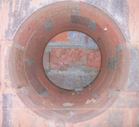
1.2. Tunnel 139

Tunnel 139 is 372m in length and is brick lined and is very similar in form to Tunnel 139.
      Between Chainage 3500m and 3900m the Expressway runs approximately parallel to Tunnel
139. As such this tunnel is aligned approximately parallel to the Expressway Cut 10 excavation. The
distance between the tunnel and the edge of Cut 10 varies from a minimum of 50m to a maximum of
150m.
       Blasting was undertaken as part of excavation for Cut 10. An assessment of the potential
vibration impacts on the brick lining of proposed blasting for Cut 10 was undertaken, with the results
of this assessment having been used to assess the structural capacity of the brick lining.

2.   HERITAGE PRESERVATION OBLIGATIONS

The HEA’s Historical Heritage Management Plan requirements stated the following:
      The Richmond Vale Railway Tunnel 134 and 139 require specialist advice and assessment for
potential impacts from vibration by a qualified vibration consultant and structural engineer. Structural
assessment will be prepared prior to any site works to determine appropriate vibration limits and
monitoring strategy.
       The Heritage Act 1977 (NSW), NSW National Parks and Wildlife Act 1974 and the Environmental
Planning and Assessment Act 1979 are the primary statutory controls protecting heritage within New
South Wales. Accordingly, HEA engaged from the outset with the authorities for the heritage aspect
of this project.

3.   RISK BASED ASSESSMENT

The assessments of Tunnel 134 and Tunnel 139 were undertaken following a risk-based approach. As
such a range of options were explored that included a ‘minimum intervention’ approach.
       From the outset, based on the team’s previous experience, the likely presence of a gap or cavity
between the lining and the rock was acknowledged to have a significant effect on the behaviour of
the brick lining in response to potential induced ground loading and ground borne vibrations.
Generally, the three possible gap conditions described below were investigated to ensure that the full
range of risks to the brick lining structure were assessed and quantified. Assessment of the Tunnel 134
stability due to construction of Cut 8 (above Tunnel 134) required consideration of three main possible
conditions which were:
      -   Condition 1: a full gap is anticipated around the tunnel perimeter above the invert between
          the brick lining and ground (this was known to be a rather conservative assumption). This
          effectively considers the tunnel lining as a free-standing structure without support from the
          surrounding ground.
      -   Condition 2: the gap between the tunnel lining and the surrounding ground is completely
          backfilled by compacted rockspoil. This assures almost full contact between ground and the
          brick lining (noted as almost full because even if it were fully backfilled it is unlikely that it
          would have been properly grouted).
      -   Condition 3: in some areas the gap is backfilled by compacted rockspoil leading to partial
          contact between the brick lining and the surrounding ground. (i.e. below tunnel axis level
          the void is infilled and above axis level a gap is assumed).
       The HEA was mandated to preserve the integrity of the heritage listed tunnels and to not cause
damage. A no-intervention approach was preferred as this would result in no disturbance to the tunnel
brick linings. Intervention works by their very nature will impact the tunnels, irrespective of whether
or not subsequent road construction causes damage to the brick structures.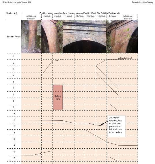
4.   HERITAGE TUNNELS DESIGN PROCESS

The interactive nature of the assessment while dealing with the heritage-listed tunnels, even to
undertake initial investigations, meant that a flowchart for the design process was developed at an
early stage. This was made clear to all stakeholders so that all parties understood the extent of the
non-intrusive and intrusive investigations, and the steps that would follow from this.

5.   SURVEYS AND INVESTIGATIONS

A balance needed to be struck between minimising the amount of intrusive testing to preserve the
heritage aspects, while gathering sufficient factual information to support the structural assessments.
Two types of intrusive investigation were undertaken of Tunnel 134. These comprised the following:
      -   A series of six cores drilled through the lining at various points (lower sidewall, mid-height
          level, and shoulders) to investigate the material properties of the lining.
      -   A vertical borehole was drilled outside of the tunnel structure from the surface down to the
          level of the tunnel. In plan the borehole is located 1.7m away from the tunnel. Within this
          hole two pressuremeter tests were done to investigate the in-situ stress regime within the
          surrounding rock.
      Non-intrusive surveys and investigations included visual observations as well as topographical
survey for the as-built profile in order to obtain a survey baseline prior to commencing excavation at
the cuts, and a detailed dilapidation survey. Tunnel T139 was inferred to have similar construction
characteristics and lining parameters.

5.1. Corings through linings
Approval was obtained from the heritage consultants to undertake a series of exploratory cores
through the lining of T134 for testing of strength and material characteristics. Six full-depth cores were
taken from various points around the lining at approximately the mid-point of the zone beneath the
deepest part of Cut 8. The cores were required for understanding of the following factors:
      -   Thickness of lining (i.e. 4 bricks or less)
      -   Presence of gap between lining and the rock
      -   Overall condition of the mortar in layering and jointing
      -   Presence of water
      -   Material testing (i.e. UCS, density, mortar composition).

            Figure 3. large diameter (200 mm) cores drilled through the brick lining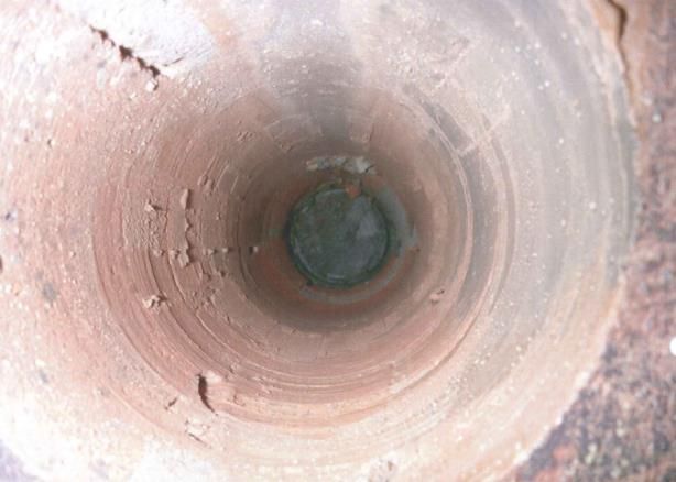
5.1.1. Lining thickness

Four of the drilled holes were 100mm in diameter, whilst two of the drilled holes were 200mm in
diameter, all drilled using a diamond coring sleeve.
        The lining was found to comprise four brick courses at the locations of the 100mm diameter
drill holes, corresponding to an overall thickness of 455mm. For the two 200mm holes, the diamond
drill sleeve was of a shorter length and therefore only around 400mm of intact core was retrieved and
the final section of lining was left in place. Consequently, the likely void behind the lining in these
locations could not be observed. However, the 200mm cores did reach a fourth brick course and so
an overall thickness of 455mm was assumed. From testing the lining thickness is believed to be
uniform around the full lining profile and over the complete tunnel length. This is the same
configuration as observed at the portal entrances to the tunnel.
      All cores were shown to be relatively well mortared across radial and circumferential joints.
Small voids were present in some mortar beds, but the overall degree of ‘completeness’ of mortaring
was subjectively estimated at >90%.

5.1.2. Presence of a gap

The average gap thickness was found to be around 125mm, although measurements taken ranged
from 75mm to 180mm (based on the findings from 100mm cores). No water was observed in the void
at the time of the investigation.

5.1.3. Material properties

Unconfined compressive strength (UCS) testing of the cores indicated an average strength of 14MPa.
This value is representative of the complete matrix strength and not just the individual brick units,
because the tested cores comprised both brick and mortar.
       A characteristic ‘design’ value of 10MPa was derived based on the statistical spread of the
results. This representative value was used for the purposes of structural modelling to describe and
quantify the overall matrix, though for the vibration analysis a lower band value of 8MPa was adopted.

5.2. Geotechnical Borehole and Pressuremeter Testing

In order to assess the stability of Tunnel 134 more precisely for the detailed assessment of the tunnel
structure, a supplementary borehole was drilled and logged. This borehole was drilled from surface
elevation down to about 7m below the level of the tunnel invert (total length 26m). The vertical
borehole was located 1.75m from the tunnel boundary.
       Information gathered from this borehole was interpreted in conjunction with other adjacent
boreholes drilled for the purpose of other HEA work. This interpretation was used to develop
geological sections around the tunnel. These geological cross sections were later used in the numerical
assessment of Tunnel 134. Within the borehole two pressuremeter tests were carried out at depths
of 17.4m and 19.8m below ground level to investigate the in situ stress regime in the surrounding
rock, as well as to determine the shear strength of rock mass around the tunnel.
      Sensitivity of the numerical model against coefficient of lateral earth pressure (K0) was assessed
by selecting K0 values that ranged from 1 to 3. These analyses confirmed that the impact of varying K0
within this range has a negligible effect on the observed extent of yielded zone. Therefore, a mean
representative coefficient of lateral earth pressure of 1.67 was adopted for the geotechnical numerical
assessments.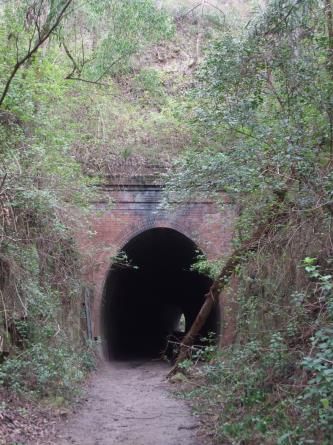
5.3. Dilapidation Survey

Both tunnels were visually inspected prior to the start of HEA construction and the findings formally
reported in a factual Dilapidation Survey Report. The purpose was to establish a baseline condition
against which comparisons could be made following the HEA construction work.
       Both tunnels were reported to be in a stable condition and generally of good quality. T134 has
a series of radial cracks towards the eastern end, attributed to mine subsidence. T139 has very few
cracks.
       The tunnel liners were constructed by multi-course brick masonry with cement-lime base
mortar, in 1904. The number of the brick courses as observed at the tunnel portal headwalls was four
bricks thick and subsequent to the dilapidation survey, diamond-drilled cores were taken to confirm
the thickness within the main section of tunnel, which were found to also comprise a four-brick lining.
      In general, the tunnels appeared to be in a good to fair condition, commensurate with their age.
The mortar was in a good condition and almost entirely intact. The intrados of the brick liners in several
areas suffered from minor and major cracks which were considered to be most likely as a result of
settlement of the tunnel structure. No noticeable severe damage or deterioration of the lining has
been noted although the eastern portal headwall of T134 had suffered major cracking and
dislodgement of some brick courses.

 Figure 4. Fieldbook data from the Tunnel 134 dilapidation survey (left) and example of existing
 brick cracking and spalling (right)

6.   VIBRATION AND LOADINGS ANALYSIS

6.1. Blasting induced vibration for T139

The construction of Cut 10 involved drilling and blasting within the thick sandstone beds that are
encountered in the lower 10 m of the cut.
       Ground vibration is generated from blasting as a result of the sudden compression of the rock
surrounding the blasthole. This results in a powerful compressive (P-wave) and shear (S-wave) wave
motion in the surrounding rock that radiates out in a spherical shape from the blasthole. These
vibration waves attenuate rapidly as they lose energy at each geological boundary and the energy is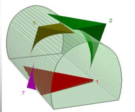
spread over a larger and larger area until they finally die out at some distance from the blasthole
(Bellairs, 2011). Figure 5 illustrates an idealised vibration trace from a blast.

                         Figure 5. Idealised Vibration Trace (Bellairs, 2011)).
       The components of any ground vibration are Displacement (D) – the distance that the particles
move back and forth, Velocity (V) - the speed that the particles are moving back and forth and
Frequency (F) –the number of times a particle completes a complete cycle each second (measured in
Hertz (Hz)).
The maximum velocity is called the Peak Particle Velocity (PPV) and is used in most of the
Environmental Licence conditions. The velocity can be used to calculate the displacement and the
acceleration caused by the ground vibrations.

6.1.1. Cut 10 blasting assumptions

Input data used for the assessment of the Tunnel 139 is as follows:
       Rock: Generally sandstone; UCS 15.2MPa; Young’s Modulus of 8.4GPa; tensile strength of
2.6MPa; sonic velocity of 2000m/s through the sandstone and the brick lining (adopted sandstone
sonic velocity is extremely low to provide a worst-case strain).
     Brick matrix: UCS 8MPa (lower bound value adopted); Young’s Modulus 14.2GPa (upper
bound/worst credible for stress calculation); tensile strength of 0.12MPa
      Blast characteristics: Induced frequency of 20 Hertz for displacement and 55Hertz for
acceleration (the worst credible frequency has been used to generate conservative values).

6.1.2. Assessment of Tunnel Lining

Two methods were used to assess the impact of blasting on the tunnel brick lining:
      Method 1:
       Calculations using recognised equations to determine ground displacement, ground
acceleration and the strain induced within the rock mass and the brick matrix as caused by blasting
vibrations. From these strain values the stress levels for each material is calculated and compared with
the strength of the materials.
      Method 2:
        This method assumes that the brick structure deforms with the ground, up to the full amplitude
of the generated compression and shear waves. A Strand7 structural model was used to assess blast
impacts. The blasting vibration is assumed to induce ultimate limit state stresses and forces within the
lining.
An UNWEDGE type analysis was undertaken for Tunnel 139, based on the site specific joint
information assuming blasting could cause block mobilisation (this analysis is described in Section 6.3).
The loading combination of the blasting vibration as well as the blasting with the dislodged wedge
resting on the tunnel lining at the time of blasting was also considered.
6.1.3. Assessment Results
Method 1: Established equations
Calculations using industry accepted equations were undertaken that consider three values of induced
PPV. The values were set, after consultation with the construction team, at 15mm/s, 20mm/s and
25mm/s. The results are presented in Table 1.
Table 1. Method 1 - Displacement and Stress Calculations results
PPV Frequency1 Displacement Acceleration Strain (microstrain) Tensile stress (MPa)
(mm/s) (Hz) (mm) (g) gap no gap gap no gap
15 20/55 0.12 0.53 11 8 0.09 0.07
20 20/55 0.16 0.7 15 10 0.13 0.09
25 20/55 0.2 0.88 19 13 0.16 0.11
Note: 1. The 20 Hertz frequency was used for displacement calculation and 55 Hertz for
acceleration; in each case the worst credible frequency has been used to generate the most
conservative value.
It is assumed that there is an amplification factor of 1.5 if a gap exists between the brick lining
and the sandstone. This factor is reduced to unity if there is full connection.
Method 2: Structural modelling
The full amplitude of the compression and shear waves was assessed to result in a displacement
of 0.3 mm. Analyses have also been run to determine the sensitivity of the brick lining to induced
movement by also investigating and making comparisons with a much higher total ground
displacement of 1.0mm.
In all cases assessed, including the 0.3mm and 1.0mm displacement cases, the induced
structural actions (i.e. bending moments and axial forces) were observed to lie within the developed
capacity profile and the induced compressive stresses within the lining were calculated to be lower
than allowable limit of 4.5MPa.
In the case of 0.3mm ground displacement, the induced tensile stresses within the lining are
calculated to be lower than the allowable limit of 0.12MPa. In the case of 1.0mm ground displacement,
the induced tensile stresses within the lining were calculated to be 0.16MPa which is higher than the
allowable limit.
6.1.4. Discussion of Findings
The Method 1 calculations of stress show that for a limit of 20mm/s PPV, blasting is expected to cause
acceptable levels of tensile stress within the brick lining. Increasing this PPV to 25mm/s results in
blasting with the potential to induce tensile stress that exceed code based acceptance limits. However,
it should be noted that these limits are inherently conservative and are not entirely relevant to thick,arched sections subjected predominantly to axial loads and bending actions caused by direct lines of
thrust.
The Method 2 assessment which uses structural numerical modelling techniques suggested that
the blasting impacts will be less significant, as compared with the results from the first approach.
However, it was judged prudent to set the PPV limit to 20mm/s for Cut 10 blasting works.
6.2. Assessment of roller and machinery induced vibration for T134
Tunnel 134 was assessed for effects from ground-borne vibrations induced by the excavation and
construction equipment working on the surface at Cut 8. The equipment that would likely create the
highest level of vibration was assessed to be a 12 tonne padfoot vibratory roller (Bellairs, 2011). It was
assumed that this will operate at the lowest formation level. As for T139, two methods of analysis
were adopted; calculations using recognised equations (Method 1) and structural modelling using
Strand 7 (Method 2).
The results of both assessments indicate that the vibration impact from the roller will be
negligible at the level of Tunnel 134. A PPV limit of 5mm/s was set for roller impacts.
6.3. Rock Wedge Analysis – Tunnel 134
For Tunnel 134, rock wedge failure assessment around the tunnel perimeter was undertaken using
the UNWEDGE analysis program. The objective was to determine the potential size of any rock wedges
that could be released onto the brick lining as a consequence of Cut 8 excavation, as triggered by
unloading or construction induced vibration.
The exposed rock jointing observed at the tunnel portals was used to determine the likely joint
sets that would exist behind the tunnel lining; two joint sets and a bedding plan were recorded during
the dilapidation survey of the Tunnel 134 portal cuttings.
Analysis was undertaken to assess the sensitivity of the size and dimensions of the formed
wedges to variations in joint orientation parameters. Considering a combination of the joint
orientation parameters that could result in the worst credible rock wedge load yielded a wedge of
14.9 tonnes (wedge reference No.2). This wedge and a smaller wedge were assumed to be released
for structural assessment of the brick lining.
To ensure that some conservatism is included, the analyses assumed no cohesion strength or
tensile joint strength. Two particular blocks have been considered. Figure 6 shows the relative size and
orientation of blocks No. 2 and 8.8 2
7 8
1 2
1
7
Top Perspective
8
2 8
2
1
7
7 1
Front Side
Figure 6. UNWEDGE output showing credible wedges Nrs. 2 and 8 which were assessed for static
loading analysis and for structural assessment of the brick lining
6.4. Summary of Ground Modelling Results
The results from the geotechnical modelling for Tunnel 134 demonstrated that the worst credible
loading of the tunnel structure will be due to wedge block release, rather than as a consequence of
rock loosened due to yielding (or overstressing) of the rock mass surrounding the tunnel. The brick
lining was therefore assessed from a structural perspective to determine if it had sufficient capacity
to resist to this mode of ground loading.
7. STRUCTURAL ASSESSMENT OF BRICK LINING
7.1. Objective
The brick lining was structurally assessed using the Strand7 numerical modelling software. A two-
dimensional ‘bedded beam’ plane frame model was created to assess the structural response of the
lining to imposed combinations of loading. The main objective was to assess the capacity of the lining
to withstand loads that may have potentially been imposed due to the works associated with Cut 8.
Taking this approach, the brick lining was modelled in two dimensions as a series of
interconnected straight members. Representative loads are applied to the lining at beam ends. The
restraint offered by the ground is replicated through the use of spring restraints placed at each node.
The spring stiffness was calculated using a linear load-deformation relationship. The calculated
stiffness was dependent upon the deformation modulus and Poisson’s ratio of the rock material and
the geometrical properties of the brick lining.
7.2. Static and Dynamic Load Cases
Loads considered to assess the capacity of the brick lining include the following:
- Self weight of the lining
- Weight of released rock blocks or ‘wedges’
- Vibration-induced ground movement that imposes structural actions and consequential
stresses.
It was assumed that groundwater does not load the outside of the brick lining. This assumption
is based on the fact that there was no visible sign of water ingress, water was not observed behind
the lining during coring of the lining and the lining can be considered to be permeable.If these blocks are indeed present above the length of the tunnel and were to become released
during Cut 8 construction then they could either load the brick lining in a uniform manner (not too
likely but plausible), or more likely, the released block rests on the lining in a more concentrated
manner (which would occur if only one edge or corner of the blocks is able to slide onto the lining).
The loading patterns assumed for structural assessment reflect both possible uniform and
concentrated loading pattern scenarios. Loading factors have been applied to these pressures to
assess the lining at the ultimate limit state. Load factors equivalent to unity have been applied to
assess the behaviour of the lining at serviceability limit state.
The UNWEDGE results were assessed to derive equivalent two dimensional strip loads for the
bedded beam analysis. The worst case wedge (Nr. 2) was calculated to apply an unfactored uniform
load of 22.4kN/m and a concentrated load of 146kN (applied across a one metre strip).
It could not be determined whether such rock blocks had already been released over the life of
the tunnel, in which case the lining is already supporting the direct load from a block. Given the greater
than 100 years age of the tunnel it is reasonable to assume that there has been a change in rock
loading since original construction. However, there is no direct visual evidence of lining distress from
such possible loadings. There is noted to be a small bulge between Chainage 5m and 9m from the
eastern portal on the northern side shoulder, which might be related to some high loadings or mining
subsidence in that area, but this was a speculative opinion.
7.3. Results and Assessed Structural Capacity of Lining
Two methods were explored to assess the capacity of the brick lining and its judged ability to withstand
the assumed loading scenarios.
7.3.1. Method 1 - Australian Standards Code-Based Assessment
Australian Standard AS3700-2001 ‘Masonry Structures’ covers the design of brick and masonry
structures in building construction. Using this standard, a code-based approach was initially used to
assess the lining. It should be mentioned that this standard gives generic guidance on the behaviour
of brickwork when used in relatively slender structures, such as walls.
The Standard was applied to estimate the capacity of the brick lining. Following the intent of
the code required the calculation of induced stresses as caused by the imposed structural actions.
These stresses were compared with acceptable calculated limits. In the case of the compression stress
limit this was set based on the representative characteristic value of 10MPa (as derived from UCS
testing). The flexural tensile limit was taken to be 0.20MPa in accordance with Clause 3.3.3 of the
masonry design code.
7.3.2. Method 2 - Alternate approach
It is recognised that brick arch structures behave differently to slender wall structures. Modern codes
do not sufficiently address the case of these thick, arched sections subjected predominantly to axial
loads and bending actions caused by direct lines of thrust.
Further, brick linings and brick arches are more ductile as a complete matrix than their individual
brick units. The lime-based mortar, if properly distributed and well bonded, helps to create a structural
matrix that responds well to internal distribution of forces.
Consequently, heritage brick arch and tunnel lining structures are known to support loads in
excess of those that would be permitted by strictly adhering to modern masonry design codes. For
this reason applying a strict codes based approach to assess the capacity of brick lining may not be
entirely appropriate.An alternate approach was therefore adopted whereby the brick matrix was assumed to behave
in a similar fashion to a concrete lining: The premise being that the brick matrix will behave
homogenously and work predominately in compression. To enable a comparison to be made of these
actions with the estimated capacity of the lining a representative moment thrust interaction diagram
was developed.
7.4. Comparison with Three Dimensional Analysis Approach
For comparison, the brick lining was also modelled in three dimensions. It is recognised that there are
certain limitations with the way in which the wedge load can be translated in two dimensional sense
(i.e. convert a three dimensional wedge load into a two dimensional strip load). As such, a three
dimensional approach allows for a more accurate representation of the triangular load pattern of the
wedge as it rests upon the lining.
The three dimensional model was created by using the Strand7 finite element program, with
the lining represented by a number of plate type elements that follow the profile of the tunnel. The
plates were given a thickness equal to the full depth of the brick structure and were assigned material
properties representative of the brick matrix.
Representative loads were applied to the lining on the plate members within the footprint of
the assumed wedge. In the case of the uniform pressure case some allowance was made for the fact
that the greater part of the load will be applied through the central mass of the wedge.
For the uniform load case the results from three dimensional modelling are fairly consistent
with that from the two dimensional modelling. However there is a more pronounced difference for
the concentrated wedge load case. The induced bending moments and consequential tensile stresses
are noted to be around half of those calculated following the two dimensional modelling approach.
The additional three dimensional modelling provided a further indication that the brick lining has
sufficient capacity to resist both the uniform and concentrated wedge load pattern case.
7.5. Discussion of Possible Failure Mechanism
The probability of a lining collapse due to the imposed loads considered in the assessment was
assessed as extremely low.
Multiple layer brick linings have a higher level of ductility than a single layer. Individual bricks
have low ductility, but the overall matrix of a multi-layer lining (considering the complex geometry of
mortaring in each direction) leads to overall higher ductility. It is known from other historic tunnels
that they have a good ability to withstand relatively large deflections in the form of bulging, before
significant cracking occurs.
Given that the lining was assumed to be mostly independent of the surrounding rock, and
therefore not already carrying high vertical rock loads, then the lining was not assumed to be in a state
of high compressive stress. As the load is applied, tensile stresses are formed in the inside face of the
lining which may lead to minor cracking but the stresses will be redistributed within the lining rather
than create one large crack. Consequently, the likelihood of a large ‘birdsmouth’ type crack through
the lining was considered to be very low, especially as the three dimensional nature of the brick
mortaring combines to create a strong matrix with the ability to yield without ‘failure’.
8. INSTRUMENTATION AND MONITORING REQUIREMENTS
An observational method of tunnel monitoring was implemented for both Tunnel 134 and Tunnel 139.
The monitoring included:
- Vibration monitoring- Movement monitoring
- Crack width monitoring
- Visual inspection.
It was recommended, and implemented, that the tunnel should be closed for public access
during the works at Cut 8, and access should be strictly limited for HEA personnel except for essential
monitoring inspections.
8.1. Instrument types and monitoring plan
8.1.1. Displacement markers
The displacement markers (DM), consisting of proprietary reflective survey targets were installed in
both tunnels
8.1.2. Vibration Monitors
Two battery powered portable vibration monitors (VM) were installed in each tunnel to measure the
peak particle velocity (PPV) reaching the tunnels due to construction activities; one on the exposed
rock invert, the other connected directly to the tunnel lining.
8.1.3. Crack width gauge
Tell-Tale crack width gauges (C) were installed on selected existing crack locations on the brick lining
prior to commencement of the construction works. These gauges were capable of monitoring the
opening or closing of a crack to an accuracy of 0.5mm.
8.1.4. Visual Monitoring Plan
Pre- and post-construction dilapidation surveys were carried out by HEA tunnel engineers. Visual
monitoring was then continued on a regular basis by site based Alliance Geotechnical Design
Representatives (AGDRs) throughout active construction periods. The timing of in-tunnel visual
inspections was coordinated with the construction works so that safety aspects are satisfied.
8.2. Trigger Values
Trigger values were set to serve as a limit upon which action is to be taken to ensure that the Alarm
(red) Value is not exceeded. Exceedance of the Trigger Value serves as a warning that the actual
behaviour of the tunnel response or the actual vibration value was not following the expected value
derived from the design calculations or from the permitted levels. The adopted Trigger Values are
presented in Table 2.
Table 2. Adopted Trigger Levels and Descriptions
Instrument Trigger values
ID
Green Orange Red [Alarm Value]
DM < 3mm 3mm – 6 mm > 6mm
VM < 17mm/s 17.1mm/s – 19.9mm/s > 20mm/s
To be specified by AGDR based on crack behaviour and other
C instrumentation records.8.3. Response
Where monitoring indicated unusual behaviour, or if the trigger levels reached the “orange” (warning
level) the monitoring results were to be checked and re-monitored immediately to confirm readings
and the monitoring frequency and extent of monitoring was to be reviewed
Where the monitoring indicated trigger levels reaching the “red” (action) level, construction
activity within the area was to be stopped immediately, personnel cleared, a review completed
including (where deemed safe) an immediate visual inspection. The monitoring frequency, extent of
monitoring and trigger levels were to be reviewed and temporary support of the tunnel considered.
8.4. Monitoring results
The results of the monitoring for both tunnels were mostly in the green range, throughout the
monitoring period. Though a few orange (warning) levels were tripped and responded to, no red
(action) triggers were tripped.
The post-construction dilapidation surveys by tunnel engineers reported that:
“there were no observable changes in the structural condition of T134 (or T139) or the portal
end walls. The tunnel remains in a similar structural condition to that when surveyed pre-construction.”
9. CONCLUSION
The HEA achieved a very successful outcome for all stakeholders. The original belief from the HEA
design team that no major intervention works would be required, based upon the team’s experience
of undertaking other similar old brick-lined tunnels, was validated through a comprehensive program
of investigation, testing and design.
The HEA was mandated to preserve the integrity of the tunnels and to not cause damage;
therefore, an agreed balance was struck between minimising the amount of intrusive testing to
preserve the heritage aspects, while gathering sufficient factual information to support the structural
assessments. A series of small and large diameter cores were taken from the linings to investigate the
parameters of the multi-layered lining, a comprehensive structural assessment involving hand
calculations and finite element modelling was completed and a programme of surveillance and
monitoring of vibrations and displacements was put in place, adopting minimal intrusion for heritage
preservation.
The outcome for the asset owner (Roads and Maritime Services), and the HEA, and for any
future public access through the tunnels as part of whatever future role they may have, confirms that
the outcome was valuable in terms of retention of the heritage listed asset and also from a cost
perspective.
10. ACKNOWLEDGEMENTS
We wish to acknowledge the NSW Roads and Maritime Authority for permission to publish this paper.
We also acknowledge the valuable contribution of Peter Bellairs in the area of vibration analysis for
the project, which has been referenced in this paper.
11. REFERENCES
Bellairs, P., (2011) “HEA – Vibration Analysis for Richmond Vale Railway Tunnels 134 and 139 from
Blasting and Vibratory Rollers 100% Report, Peter Bellairs Consulting Pty Ltd”, report to the Hunter
Expressway Alliance, dated 9th February 2011You can also read