The optical design of the LiteBIRD Middle and High Frequency Telescope
←
→
Page content transcription
If your browser does not render page correctly, please read the page content below
The optical design of the LiteBIRD Middle and High
                                                                      Frequency Telescope
                                                      L. Lamagnaa,r , J.E. Gudmundssonb , H. Imadac , P. Hargraved , C. Franceschete,s ,
                                                     M. De Petrisa,r , J. Austermannf , S. Bounissoug , F. Columbroa,r , P. de Bernardisa,r ,
                                                     S. Henrot-Versilléh , J. Hubmayrf , G. Jaehnigi , R. Keskitaloj , B. Maffeig , S. Masia,r ,
                                                T. Matsumurak , L. Montierl , B. Motl , F. Noviellod , C. O’Sullivanm , A. Paiellaa,r , G. Pisanoa ,
                                                  S. Realinie,s , A. Ritaccog,q , G. Savinin , A. Suzukio , N. Trappem , and B. Winterp , for the
                                                                                    Litebird Joint Study Groupt
arXiv:2101.03833v1 [astro-ph.IM] 11 Jan 2021

                                                                     a
                                                                              Physics Department, Sapienza University of Rome, Italy
                                                       b
                                                          The Oskar Klein Centre, Department of Physics, Stockholm University, Sweden
                                                                  c
                                                                    National Astronomical Observatory of Japan, Osawa, Mitaka, Japan
                                                                            d
                                                                              School of Physics and Astronomy, Cardiff University, UK
                                                                   e
                                                                     Physics Department, Università degli Studi di Milano Statale, Italy
                                                                f
                                                                  National Institute of Standards and Technology, Boulder, Colorado, US
                                                                     g
                                                                       Institut d’Astrophysique Spatiale, Université Paris-Saclay, France
                                                                        h
                                                                          Université Paris-Saclay, CNRS/IN2P3, IJCLab, Orsay, France
                                                     i
                                                       Center for Astrophysics and Space Astronomy, University of Colorado Boulder, US
                                                               j
                                                                 Computational Cosmology Center, Lawrence Berkeley National Lab, US
                                                       k
                                                         Kavli Institute for the Physics and Mathematics of the Universe, Kashiwa, Japan
                                                             l
                                                               Institut de Recherche en Astrophysique et Planétologie, Toulouse, France
                                                                   m
                                                                     Department of Experimental Physics, Maynooth University, Ireland
                                                               n
                                                                  Department of Physics and Astronomy, University College London, UK
                                                                              o
                                                                                Physics Division, Lawrence Berkeley National Lab, US
                                                           p
                                                             Department of Space and Climate Physics, University College London, UK
                                                                   q
                                                                     Département de Physique, Ecole Normale Supérieure, Paris, France
                                                                                           r
                                                                                             INFN Sezione di Roma1, Italy
                                                                                           s
                                                                                             INFN Sezione di Milano, Italy
                                                                         t
                                                                           LiteBIRD Joint Study Group Members are listed at this link

                                                                                                ABSTRACT
                                               LiteBIRD is a JAXA strategic L-class mission devoted to the measurement of polarization of the Cosmic Mi-
                                               crowave Background, searching for the signature of primordial gravitational waves in the B-modes pattern of the
                                               polarization. The onboard instrumentation includes a Middle and High Frequency Telescope (MHFT), based
                                               on a pair of cryogenically cooled refractive telescopes covering, respectively, the 89-224 GHz and the 166-448
                                               GHz bands. Given the high target sensitivity and the careful systematics control needed to achieve the scientific
                                               goals of the mission, optical modeling and characterization are performed with the aim to capture most of the
                                               physical effects potentially affecting the real performance of the two refractors. We describe the main features of
                                               the MHFT, its design drivers and the major challenges in system optimization and characterization. We provide
                                               the current status of the development of the optical system and we describe the current plan of activities related
                                               to optical performance simulation and validation.
                                               Keywords: LiteBIRD, Cosmic Microwave Background, polarization measurements, millimeter wavelengths,
                                               refractive telescopes, space telescopes, optical modeling
                                                  Corresponding author information:
                                                  E-mail: luca.lamagna@uniroma1.it, Telephone: +39 (0)6 4991 4287

                                                                                                       1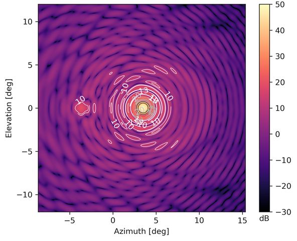
1. INTRODUCTION
LiteBIRD is a planned JAXA satellite which will be inserted into a L2 Lissajous orbit by the end of 2020s with a
JAXA H3 rocket, for three years of observations.1 The main aim of this experiment is to detect or constrain the
amplitude of a hypothesized primordial B-mode signal in the Cosmic Microwave Background (CMB). LiteBIRD
comprises two telescopes, the Low Frequency Telescope (LFT), with a frequency range of 34-161 GHz and the
Middle and High Frequency Telescope (MHFT) operating in the 89-448 GHz range. Together, the two instruments
will observe the sky in 15 spectral bands. This proceeding is dedicated to the optical design of the MHFT. We
will review the baseline design and discuss initial results of various optical simulations.

               2. MIDDLE AND HIGH FREQUENCY TELESCOPE DESIGN
2.1 Choice of refractive over reflective design
Polarization modulation affected the MHFT design from its earliest development phases. In fact, the MHFT
trade-off analysis has been mainly driven by the constraints due to the Half Wave Plate (HWP) technology.
The wide frequency coverage, from 89 GHz to 448 GHz, associated to the limited mass budget placed strong
constraints on the HWP material. The weight of a multi-layer sapphire HWP, and the difficulty in applying
an anti-reflection coating (ARC) for the highest frequency channels led to discard this solution in favour of a
metamaterial-based design (mHWP).2–5 In the framework of the ESA CDF (Concurrent Design Facility) study,
the two following designs have been studied:

   • Option A - fully reflective: single reflective optics + reflective mHWP3 covering the full frequency range.

   • Option B - fully refractive: two telescopes with refractive optics + transmissive mHWP,2 by splitting the
     total frequency range into mid-frequency (MFT) and high-frequency (HFT) ranges.

Following the end of the ESA-CDF study, further work and optimizations have been done on the design of both
option A & B and most of the issues identified during the CDF have been addressed. Among the possible imple-
mentations of mHWP technology, the safest and less prone to unknown optical systematics was determined to be
a transmissive, mesh-based multilayer design, where the incoming polarization is rotated while being transmitted
through a rotating flat reactive structure, located along the optical path from the sky to the telescope. Given
the broad spectral coverage, a separation of the MHFT into two distinct optical assemblies (MFT, 89-224 GHz
and HFT, 166-448 GHz) has been proposed, each with its own polarization modulator, in order to mitigate the
bandwidth issues of the mHWP technology. In combination with mass/volume considerations for the telescope
assemblies, and other major system-level tradeoff considerations, this study brought to the choice of the fully
refractive, on-axis dual-lens solution as a baseline for both the MFT and for the HFT (see Fig. 1).
    In this configuration, the continuously rotating polarization modulator is the first optical element of the chain,
and two AR-coated plastic lenses in a telecentric configuration focus radiation on a flat focal surface where the
Transition Edge Sensor (TES) arrays are accommodated. The aperture stop of the system is located skywards of
the objective lens, and the HWP is placed skywards of the aperture stop, just as close to it as practically allowed
by mechanical and thermal considerations, in order to optimize the size and mass of the PMU mechanism. Quasi-
optical filters, based on plastic-embedded metal-mesh technology, are placed along the optical chain to prevent
far-infrared radiation from propagating all the way to the focal plane, controlling the overall power loading on
the detectors. Microwave absorbing layers on the tube walls and around the aperture stop are implemented to
ensure further control of in-band stray-light. Final frequency selection and band refinement for each subset of
detectors take place on the focal plane assemblies. The whole telescope unit, including the tube, the PMU, the
lenses and the filters, is cooled down to 4.8 K. A 1.8 K cold baffle surrounds the 100 mK Focal Plane Unit (FPU),
to provide both additional loading control for the environment surrounding the FPUs and a stage of magnetic
shielding for the Transition Edge detectors. Cold forebaffles at the sky input of the tubes will be designed to
ensure reliable control of beam far sidelobes and prevent radiation pickup from the emissive payload structure
in close proximity to each telescope.
   The major strengths of the fully refractive configuration are:

                                                          2
Figure 1. MHFT overview, the various subsystems composing the telescopes are identified, and held by the mechanical
structure. The optical front baffles still have to be designed.

   1. In addition to being simple and conventional, the design strongly benefits from the broad expertise gained
      on many current and upcoming sub-orbital CMB experiments, such as BICEP2,6 Keck,7 SPIDER,8 LSPE,9
      and Simons Observatory10

   2. With these very compact on-axis designs, the MFT and HFT telescopes offer the necessary design flexibility
      to match the volume and mass constraints, to mitigate stray-light issues, and to split the entire frequency
      range in two bands.
   3. This choice has also obvious simplifications for the design of the separate filtering chains.

   4. Dealing with two smaller compact telescopes will be considerably more practical for the Assembly Integra-
      tion and Test (AIT) and the Assembly Integration Verification (AIV) phases of the project, and for all the
      ground calibration activities.

    On the other hand, the use of dielectric lenses implies the need for a careful design and modeling, and a
dedicated performance validation effort. This is needed to address both the issues related to intrinsic frequency,
polarization and temperature-dependent properties of the refracting materials, as well as to understand the higher
order optical coupling effects arising from a broad set of non-idealities, such as imperfect dielectric-to-vacuum
matching at the optical interfaces (usually compensated through custom, but not ideal, anti-reflection coatings),
imperfectly absorbing tube surfaces and focal planes, scattering off internal surfaces, and thermal radiation
pickup from the payload environment. Some of these issues are also exacerbated by the modulation from the
transmissive HWP: since scattered radiation is likely to be polarized with a well defined but not optimized
frequency dependence. If the stray optical paths involve a reflection on the rotating HWP, this will result in a
partial modulation of this stray radiation and therefore in a spurious contribution in the signal bandpass, should
this radiation propagate back on the detectors.

2.2 Baseline optical design parameters
The LiteBIRD MHFT optical designs are based on a simple two-lens refractor concept. Figure 2 shows a ray trace
diagram of the two telescope designs. Both telescopes employ two polypropylene (PP) or ultra-high molecular
weight polyethylene (UHMW-PE) lenses with an assumed index of refraction nr = 1.52. The final choice of the
plastic material will affect the lens profiles very marginally, even if different high-frequency losses for the plastics
may be relevant for HFT.

                                                           3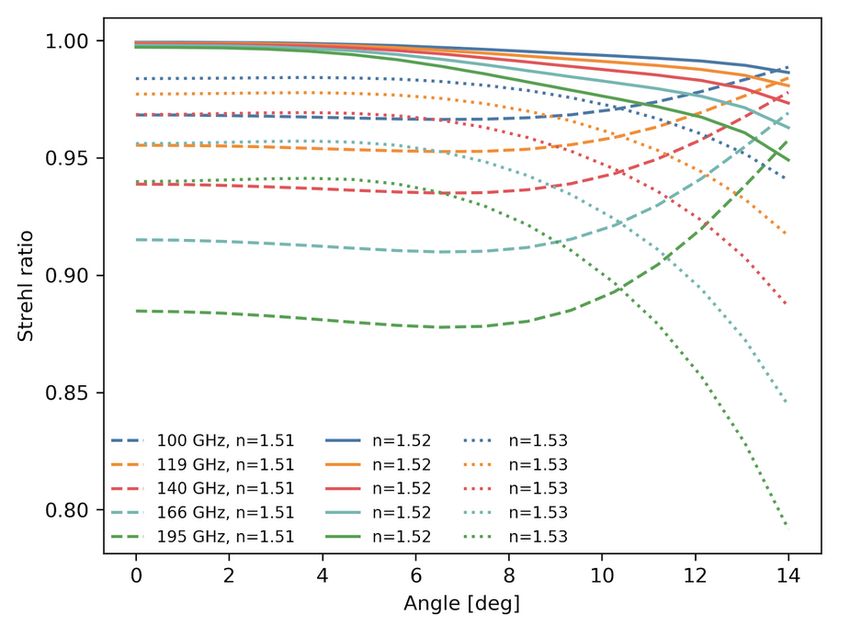
���                                                                                                                                 ���

                                                                                                                                         �   ���
         ����

                                                                                                                                         �   ���
         ����
                                                                                                                                             �   ��
  ����

                                                                                                                               ����
             �  �                                                                                                                                � �

                                                                                                                                             ���
         ����
                                                                                                                                         ����

         ����
                                                                                                                                         ����

                 ����   �
                        �   ����   ����   ����   �   ���   �   ���   ����   ����   ����   ����   �����   �����    �����                              ����   ��       ����      �   ���        ����          ����   ����   ����        ���
                                                                                                                                                                                                                                      �          ����
                                                                 ����                                                                                                                                ����

Figure 2. Ray diagrams of MFT (left) and HFT (right). The on-axis and off-axis fields (14 deg) are the blue and red rays,
respectively. The telescope aperture is located at z = 0.
                 1.00
                                                                                                                                                                         MFT                           HFT
                                                                                                                                                     2.45
                 0.98
                                                                                                                                                     2.40

                                                                                                                              Effective f-number
                 0.96
 Strehl ratio

                                                                                                                                                     2.35
                 0.94                                                                                                                                2.30
                                       MFT 100 GHz
                 0.92                  MFT 195 GHz                                                                                                   2.25
                                       HFT 195 GHz
                                       HFT 402 GHz
                 0.90                                                                                                                                2.20
                            0          2     4      6     8 10                                   12          14                                                  0       2               4        6     8 10                     12         14
                                               Field angle [deg]                                                                                                                             Field angle [deg]
Figure 3. Left: Strehl ratio as a function of field angle for the lowest and highest frequency bands on the MFT and HFT.
Right: The effective (working) f -number variation as a function of field angle for the MFT and HFT.

   The lenses will employ one or multi-layer anti-reflection (AR) coatings to support the broad frequency range
covered by these telescopes.11 A slight preference for PP lenses emerges in this context, due to the higher melting
temperature making the ARC application easier and more reliable.
    The aperture stop is located skywards of the primary lens such that the two telescopes both have an effective
(working) f -number of 2.2 at the center of the focal plane. The effective f -number grows to 2.40-2.45 at the edge
of the focal plane. The Strehl ratios and the f-number of the MFT and HFT are shown in Figure 3. It is clear
that the designs support more than a 28° diffraction-limited field of view. The telescope apertures, which are
placed skywards of the primary lens, have diameters of 300 mm and 200 mm for the MFT and HFT, respectively.
The designs are fully telecentric with a chief ray angle of incidence not exceeding 0.1° across the field of view.

                                              3. PRELIMINARY OPTICAL MODELING RESULTS
Numerical studies are required for the design optimization of MHFT, both because of the complex interplay
between different physical aspects of radiation propagation through the different parts of the telescopes, as
well as for the broad range of frequencies covered by the two telescopes. Commercially available software tools
provide an effective and informative support in this activity, but they often need to be complemented by custom
post-processing tools developed for specific studies. In addition, dielectrics with compliant nominal properties
are used as lens materials and in the absorptive coatings. Especially at the highest frequencies, these need to be
carefully treated in order to capture all the relevant processes affecting the telescope performance, including e.g.
dielectric losses and unwanted polarization-sensitive scattering,
         Numerical simulations are being performed:

                                                                                                                          4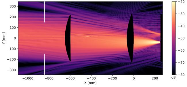
Figure 4. MFT Strehl ratio across the field of view, as a function of lens refractive index.

   • At the subsystem level, to refine the design of telescope elements, identify critical tolerances, optimize sur-
     face coatings, investigate the broadband behavior of surface shapes and inspect the feasibility of competing
     solutions for focal plane coupling.
   • At the system level, in order to provide a global picture of the receiver performance, e.g. by delivering
     performance-relevant quantities like polarization-sensitive sky beams and realistic sidelobe pickup as a
     function of the detector position on the focal plane. These data products are helpful to inform more
     accurate TOD-based simulations of the observed microwave sky and to provide inputs for the design and
     planning of RF–testing and calibration procedures.

3.1 Preliminary tolerancing results.
Simple geometrical tolerancing has been performed using Zemax. This work suggests that the MHFT design is
relatively robust to error in alignment that result in translation and rotation errors with respect to specifications.
Out of the tolerancing studies considered so far, the constraints on lens index of refraction are found to be the
most stringent. By using the Strehl ratio as a simple performance metric, we find that an uncertainty of 0.01
in the plastic refractive index (assuming a reference value of n = 1.52), preserves a Strehl ratio greater than
0.8 across the whole field of view of MFT (see Fig. 4) More advanced tolerancing studies are planned for future
design iterations. These will include surface error analyses on different scales, more realistic representation of
the tube structures and a dedicated focus on the high-frequency behavior of dielectric materials for the HFT.

                                            MFT                                             HFT
                           100      119      140      166         195      195      238     280      337        402
      FWHM [arcmin]       37.8      33.4    30.4     28.3         27.2    28.6     24.6     22.4    20.6       17.7
      Edge taper [dB]      -9.5    -13.1    -17.9    -24.9       -34.3     -8.4    -12.1   -17.1    -24.6      -26.1
      Ellipticity         0.002    0.003    0.005    0.008       0.011    0.003    0.005   0.008    0.010     0.0115

Table 1. Mean predicted optical parameters for the each of the five MFT and HFT frequency bands. The mean is estimated
from 12 and 7 simulations for MFT and HFT, respectively (see dicussion in Section 3.2).

3.2 Baseline physical optics simulation results
Simple physical optics simulations are used to predict the far field response of the proposed optical design.
These simulations can be used to study the expected variation in beam size and beam ellipticity as a function of
frequency and field location. The same framework can be used to estimate spillover past lenses and the aperture
stop (see Section 3.3). For this work, we make use of a simulation framework first described in Ref. 12. We refer

                                                             5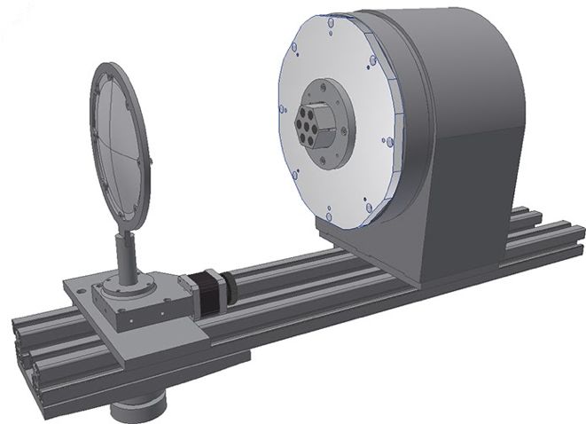
the reader to this work for a more detailed discussion of the simulation and analysis methodology. Key optical
properties derived from these physical optics simulations are summarized in Table 1.
    The physical optics simulations use Gaussian pixel beams as input. The width of the Gaussian beams
correspond to the assumed pixel apertures, 11.6 and 6.6 mm for the MFT and HFT, respectively. In order to
optimize time usage, the simulations are run for a single frequency within a given band. Moreover, because of
the azimuthal symmetry of the two-lens refractor design, we only run simulations for a handful of detectors along
a radial line from the center of the focal plane out to its edge, this number of detectors being 7 and 12 for the
MFT and HFT, respectively. These physical optics simulations involve only the two lenses and the cold aperture
stop, also assuming perfect mechanical alignment and material properties while ignoring any reflections. Figure 5
shows the predicted beam ellipticity as a function of field angle for the MFT and HFT frequency bands. We
define the beam ellipticity as
                                                     σmax − σmin
                                                 e=               ,                                            (1)
                                                     σmax + σmin
where σmax and σmin correspond to the widths of the best fit Gaussian envelope to the semi-major and semi-minor
axis of the co-polarized far field beam response.
   As expected, the beam ellipticity is predicted to grow with field location and frequency. We note however
that the ellipticity is observed to be quite low even at the edge of the 28° field of view at the highest frequencies.
For comparison, the mean beam ellipticity of the 100 and 143-GHz channels on Planck was roughly 0.085 and
0.020, respectively.13

                0.040         100 GHz     166 GHz                                    0.040         195 GHz     337 GHz
                0.035         119 GHz     195 GHz                                    0.035         238 GHz     402 GHz
                0.030         140 GHz                                                0.030         280 GHz
                0.025                                                                0.025
  Ellipticity

                                                                       Ellipticity

                0.020                                                                0.020
                0.015                                                                0.015
                0.010                                                                0.010
                0.005                                                                0.005
                0.000                                                                0.000
                        0.0      2.5    5.0 7.5 10.0 12.5                                    0.0      2.5    5.0 7.5 10.0 12.5
                                         Angle [deg]                                                          Angle [deg]
                Figure 5. Simulated MFT and HFT beam ellipticity as a function of field angle for all 10 frequency bands.

3.3 Spillover simulation results
Accurate modeling of optical spillover inside the optics tube is necessary for sensitivity estimates. We can use
the physical optics modeling results to estimate the beam power that misses the secondary and primary lenses
and the aperture stop. By summing up the optical power that misses these optical elements and comparing it to
the pixel beam model input, we can estimate the fractional cold spillover. Further discussion of this simulation
approach is described in Ref. 12.
    As the expected pixel beam response of the proposed detector designs was not available, these simulations rely
on the same Gaussian pixel beam that is used for analysis described in Section 3.2. Figure 6 shows the predicted
edge taper as a function of focal plane location for the MFT and HFT. For off-axis pixels, we define the edge
taper as azimuthally averaged beam power along the stop edge. As expected, we see a slight increase in the edge
taper as we move across the focal plane. It is important to note that because of the fixed pixel diameter assumed
for the MFT and HFT, we observe significant shift in the edge taper as a function of frequency. Consequently,
the conservative edge taper for the high-frequency bands should help reduce sidelobe response.

                                                                   6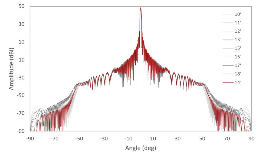
100 119 140 166 195 GHz 195 238 280 337 402 GHz
5 5
10 10
15 15
Edge taper [dB]
Edge taper [dB]
20 20
25 25
30 30
35 35
40 40
0.0 2.5 5.0 7.5 10.0 12.5 0.0 2.5 5.0 7.5 10.0 12.5
Angle [deg] Angle [deg]
Figure 6. MFT and HFT edge taper as a function of field angle for all 10 frequency bands.
3.4 Inclusion of forebaffle effects
In addition to the dual lens optical path response, the final radiation pattern is affected by several elements of
the MHFT telescopes – e.g. forebaffle, mHWP, filters, tube with internal absorber, ARC and optical properties
of the lenses among the few – each of them having an impact, possibly negligible, on different angular ranges.
The most off-axis pixels of the focal plane are characterized by an intrinsic degree of asymmetry which could
magnify the effect of these telescope elements on the beam. Therefore, we study the impact of each individual
item on the resulting beam separately, in order to assess the angular range which is mainly affected as well as the
relevant intensity in terms of sidelobe levels. An analysis to optimize the telescope components is also desirable,
as it allows for an estimation of the sensitivity of the beam response to these effects; e.g. the tube diameter, the
properties of the tube internal absorber, forebaffle length, etc.
100 GHz
30.0
119 GHz
140 GHz
20.0 166 GHz
195 GHz
10.0
Amplitude (dBi)
0.0
-10.0
-20.0
-90.0 -45.0 0.0 45.0 90.0
Angle (degrees)
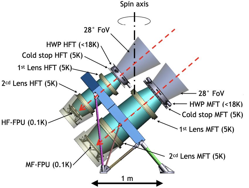
Figure 7. Left: MFT telescope model used to simulate the forebaffle flare angle impact on the MFT radiation patterns.
The telescope tube is not included in the simulation, and the forebaffle is assumed to be completely absorbing, so that
only its aperture is considered. Right: the MFT beam former response is similar to that of a sinuous antenna coupled to
a lenslet.
As an example, we now discuss the effect of the forebaffle size on the MFT beams. We simulated the MFT
optics with physical optics, including the feed, the two lenses, the cold stop aperture and a fully absorbing
forebaffle, as shown in Figure 7. Keeping the total length of the forebaffle fixed to its nominal value of 270
mm, we varied the flare angle within the range of 10° to 18° (the entrance aperture of the forebaffle is modified
accordingly between 395 and 475 mm) to verify the impact on the radiation pattern at the MFT frequencies of
100, 119, 140, 166 and 195 GHz.
Figure 8 depicts the co-polar beams (phi = 90°) at 100 GHz for the on-axis pixel. Lower flare angles determine
7Figure 8. Radiation pattern at 100 GHz for the MFT on-axis pixel with varying forebaffle flare angle.
an increase of order of 3.5 dB in the intermediate sidelobe levels in the angular region between 10 and 15 degrees
and a substantial increase of the far sidelobes at angles larger than ±50 degrees, still about 80 dB below the
main directivity.
The entire analysis includes the co-polar and cross-polar response for on-axis and off-axis pixels on the focal
plane. Similar analyses will be performed for the different elements of the MHFT telescopes in order to assess
their impact on the final beam, also by combining those components which have a non-negligible impact on the
optical response.
3.5 Feed simulations
The feed beam patterns have been redundantly simulated with mode-matching and full 3D electromagnetic
modeling software. After validating the basic results, the full-wave software Ansys HFSS has been used to
generate a first set of simulations, thus providing lenslet beam patterns at 89–112 GHz for MFT and feedhorn
beam patterns in the 402 GHz band of HFT. These feed patterns have been used so far for preliminary studies
of spillover effects. Work is underway to include these patterns in a full telescope simulation to inform TOD-
based simulations with more realistic beams. A longer-term project involves therefore the production of the full
frequency-dependent set of lenslet and feed patterns. Such activity is expected to be particularly useful for the
HFT, for which a full system-level numerical simulation is well out of reach of the available modeling/computing
resources.
MFT
The MFT focal plane will feature sinuous antenna-coupled detectors with a silicon AR-coated lenslet.14, 15 The
lenslet diameter is 12 mm for all the MFT bands. A sketch of the device and the corresponding simulated beam
patterns are shown in Fig. 9.
The MFT detector array consists of seven hexagonal wafers, each of which holds 61 pixels. To observe multiple
bands, band-pass filters and multiple TES detectors are built into multichroic assemblies. The total number of
the detectors in MFT is 2074.
HFT
The HFT will employ horn-coupled detectors.14 The horn diameters are 6.6 mm for the 195 to 338-GHz bands and
5.7 mm for the 402 GHz band. The 6.6-mm horns make two 127-pixel arrays with planar Ortho-Mode Transducers
(OMTs). Each 6.6-mm horn array can observe two bands and two linear polarizations, simultaneously, so that
254 TESs are employed. The 5.7-mm horns make a 168 pixel monochromatic array with OMT. The total number
of the detectors in HFT is 1354. Two different horn profiles have been proposed for the 402 GHz detectors. Both
are based on Si platelet technology16 and are shown in the left panel of Fig. 10. The first profile is a corrugated
8tAR# = thickness of AR 20 Co–pol φ = 0 ◦
eAR# = dielectric constant of AR
AR3
Co–pol φ = 45 ◦
AR2
AR1 10 Co–pol φ = 90 ◦
Cross–pol
0
Gain [dB]
−10
−20
Dielectric constant of Si = 11.7
Pixel pitch −30
TSeatingWafer Dielectric constant of Si = 11.7
Tdetwafer Dielectric constant of Si = 11.7 −40
TBackshort Sinuous Antenna
Backshort (perfectly conducting metal)
−75 −50 −25 0 25 50 75
Angle [deg]
Figure 9. Left: sketch of baseline MFT coupling devices, made of a sinuous antenna and AR-coated silicon lenslet Right:
Beam cuts at 100 GHz. Copolar beam cuts are shown at φ = 0◦ , 45◦ and 90◦ . Maximum cross-polarization is shown for
φ = 45◦ .
feedhorn made of 101 150µm–thick platelets, while the second is a spline-profile horn, adapted to the platelet
technology in order to be made of 61 250µm–thick platelets. Nominal performance for both models is excellent,
as summarized in Tab. 2.
Horn type Corrugated Spline-profiled
Spillover efficiency avg (max) 0.924 (0.933) 0.968 (0.986)
Co-polar beam asymmetry avg (max) 0.0037 (0.057) 0.0017 (−0.053)
Cross-polarization avg (max) 3.6 · 10−4 (4 · 10−3 ) 13 · 10−4 (6 · 10−3 )
Reflection loss avg (max) −31dB (−25dB) 23dB (−17dB)
Table 2. Synthetic data for proposed HFT horn geometries. Beam-integrated quantities refer to a nominal coupling F-
number of 2.2. Maximum and average values refer to the highest HFT frequency channel, with a center frequency of
402 GHz and a 25% bandwidth.
In order to check the consistency of current fabrication and assembly tolerances of silicon platelet feedhorns
with the global coupling requirements of the HFT, an analysis has been started to investigate the impact of
plate-to-plate misalignment on beam properties. Fig. 11 shows that the copolar and cross-polar beam patterns
are very stable for both horn designs with 3µm rms displacements between neighboring platelets. This level of
alignment has been achieved in previous silicon platelet horn builds by use of a simple pin and slot alignment
method. The band-averaged HFT spillover efficiency of the corrugated (spline-profiled) horn is ∼ 93% (∼ 96%),
and changes by no more than 2% over 100 misalignment realizations for either profile. We also find that the
peak cross-polar response is < 0.7% for all realizations. These results hold up to the upper edge of the highest
HFT band, suggesting that both designs are suitable for HFT implementation. Additional simulation work is
underway to investigate more extreme or self-correlated misplacement profiles along the horn.
4. MODELING CHALLENGES AND MITIGATING ACTIONS
Optical Ghosts
Telescope ghosts are position-sensitive artifacts originating by field propagation across the optical system, due
to non-ideal behavior of the optical elements and of supporting/surrounding structures. A few examples are an
imperfect absorption by tube walls, non-ideal AR coatings on HWP and lens surfaces, with consequent frequency
and polarization dependent reflection and scattering, and an imperfectly matched focal plane coupling. Radiation
9Corrugated
20
0
−20
−40
Gain [dB]
Co–pol φ = 0 deg
−60 Co–pol φ = 45 deg
Co–pol φ
−75 −50= 90 deg
−25 0 25 50 Spline
75
20
Cross–pol
0
−20
−40
−60
−75 −50 −25 0 25 50 75
Angle [deg]
Figure 10. Left: Corrugated and spline-profiled feedhorns proposed for the HFT highest frequency baseline channel.
Right: Beam cuts of candidate HFT feedhorns at 450GHz. Copolar beam cuts are shown for φ = 0◦ , 45◦ and 90◦ .
Maximum cross-polarization is shown for φ = 45◦ .
30 30
Co–pol Co–pol
20 Cross–pol 20 Cross–pol
10 10
0 0
Gain [dB]
Gain [dB]
−10 −10
−20 −20
−30 −30
−40 −40
−50 −50
−75 −50 −25 0 25 50 75 −75 −50 −25 0 25 50 75
Angle [deg] Angle [deg]
Figure 11. Beam cuts of candidate HFT feedhorns for random, 3µm rms platelet misplacements. Copolar beam cuts are
shown for φ = 0◦ . Cross-polarization is shown for φ = 45◦ . Left: Corrugated feedhorn. Right: Spline-profiled feedhorn.
Colored bands highlight the region containing 68% of realizations.
re-launched from these effects on optical paths getting it at least partially refocused on the focal plane will be
detected as more or less diffused structures superimposed over the actual image of the sky, potentially yielding
systematic effects in signal recovery. Preliminary physical optics simulations have been run to check the ability
of common simulation algorithms to capture some of these effects. As an example, Fig. 12 shows the effects
of non-ideal single-layer ARCs on the 90 GHz beam pattern and field distribution in a simplified version of the
MFT, for a nominal pixel position 40 mm off the center of the focal plane.
The effort towards a robust modeling and understanding of the relative contributions of ghosts to the system-
atic effects is still ongoing. Scattering effects, in particular, are not easily captured in existing software codes,
especially when system level simulations are performed. This is why a validation campaign based on experimen-
tal measurements on real-life sample systems is needed to ensure a correct evaluation of the ghosting problem
across the whole MFT and HFT frequency range.
10Figure 12. Left: Optical ghosting at 90 GHz resulting from the combined effect of non-ideal ARC on MFT lenses and
imperfect absorption on the focal plane, as seen in the telescope far field. Radiation is launched from a focal plane
positon corresponding to a 40 mm off-center detector. Right: Intensity distribution in the telescope plane for the same
combination of effects.
Polarization Modulator
The continuous rotation by the HWP of the input polarization provides quasi-simultaneous observations of the
I, Q and U Stokes parameter across the focal plane pixels. In addition, thanks to the HWP modulation, the
input polarization is shifted at higher frequency with reference to the slower signal fluctuations that are usually
associated with any kind of noise coming from the instrumentation: electronics, cryogenics etc.
However, imperfections of the HWP lead to the modulation of the background signal which appears to peak
at harmonics of the HWP rotation frequency in the data spectrum. This kind of instrumental noise is known as
HWP parasitic signal (HWPSS) and has been observed in previous experiments, such as Maxima,17 EBEX,18
NIKA.19 Methods are available to model this signal and subtract it in the data analysis step from the TOD of
each detector.19
In addition, any departure from a Gaussian shape of the beam can cause leakage of the total intensity to
polarization, resulting in a beam pattern deformed in polarization.19 This effect might be observed in the Stokes
Q and U maps of an unpolarized source and we refer to it as instrumental polarization. The modelling of this
beam pattern is usually more difficult20 for large arrays of detectors because each detector might have a slightly
different beam. For this reason the knowledge of the beams and the study of the effect through simulations and
laboratory tests with the full optics, including the HWP, is crucial to constrain such a systematic in the final
data.
Absorbers
Quasi-optical filters will be designed and implemented to reject unwanted radiation propagating from the sky all
the way down to the focal plane. Nonetheless, in-band radiation may picked up as a consequence of scattering off
or re-emitted from optical elements or devices along the optical chain. As already anticipated, this is responsible
for excess loading and/or image artifacts on the focal planes. The use of absorbing coatings and materials, possibly
complemented by a careful shaping of the internal surfaces of the tube assemblies, is a standard technique to
mitigate such issues. Ideally, a perfect absorber emits an exact blackbody spectrum (in which case the loading on
the focal planes depends only on the absorber temperature), absorbs efficiently radiation well away from normal
incidence, and features a large thermal inertia, so that the radiating/absorbing properties don’t exhibit thermal
drifts which might ultimately determine dangerous time-constant effects in the detectors response. In addition,
any candidate absorber for the MHFT tubes must comply with the tight mass allocation constraints and meet
the requirements for space qualification.
A wealth of space-qualified absorbers have been proposed in the past for far-infrared missions.21, 22 These
are mostly based on dielectric molds loaded with conductive scattering powders, and their characteristics are
available in the literature down to THz frequencies. Other materials, like Eccosorb CR-110, have long been
known to approach blackbody emissivity down to tens of GHz.23 Recent work has been devoted to characterize
11loaded epoxy powders as absorbers at THz and sub-THz frequencies.24–26 Metamaterial-based absorbers, based
on low-frequency adaptations of THz metamaterial designs27 have also been recently proposed, even if their
readiness for space environment and actual applicability on non-flat surfaces have yet to be explored. 3D-printed
absorbing structures have also been recently demonstrated in selected bands below 230 GHz.28
Regardless of the technology of the adopted solution, MHFT absorbers need to be carefully measured and
modeled to assess their behavior at low temperature (the MFT and HFT tubes operate at 5K) in terms of
incidence-, polarization- and frequency-dependent reflectance and scattering properties. Most of these effects
cannot be easily implemented in numerical simulations and their treatment must rely on experimental data for
the specific materials involved at the MHFT frequencies. Absorbers around the cold aperture stop, in particular,
are a source of major concern because of the close vicinity to the warm PMU mechanism. They are meant to
mitigate the excess radiation leaking in the tube through diffraction and scattering off the edges of the aperture
stop.
The current effort for MFT and HFT absorber studies is twofold:
• Representative subsystem-level simulations are performed to optimize surface shaping as a function of
coating thickness, typical illumination and likelihood of unwanted pickup.
• A systematic characterization campaign has been started to update the available information on known
materials or molds thorugh dedicated measurements on samples: spectral/polarimetric room-temperature
measurements of reflectance and scattering will be followed by representative tests in cold environment.
The results of these studies are meant to inform the tradeoff between electromagnetic performance and impact
on the mass budget, and to inspect the need for a passive or active thermal control of the most sensitive regions
of the tubes.
5. SUPPORTING LABORATORY MEASUREMENTS
The overall LiteBIRD requirements, dictated by the science goals, translate into a need in the knowledge of
the optical system to unprecedented levels. We therefore need to rely extensively on dedicated experimental
characterisation in order to verify our assumptions, build and consolidate our models. These experimental
measurements need to happen at different levels, starting from material characterization to sub-system and
system-level performance assessment. Similarly to any space mission, several models of the instruments will
be developed over the years in order to build our knowledge of the overall performances of MHFT (typically
prototype, qualification model followed by the flight model). However several fundamental questions need to
be answered very soon in order to gain confidence in the results of our modelling tools. Questions such as the
knowledge of material optical characteristics at very low temperature, impact of potential in-homogeneity of the
lens material, accuracy of refractive optics modelling, mainly when polarisation is concerned, still need to be
answered to the required accuracy level. Therefore preliminary characterisations will be performed in parallel, on
materials and on breadboard models, starting from a very simple configuration (BB1 - BreadBoard 1) evolving
then to more complete and complex optical concepts.
BB1 comprises only one lens coupled to a small array of corrugated feedhorns (left panel of Fig. 13), allowing
to compare predicted and measured co- and cross-polarisation beams for on-axis and off-axis pixels. The first
GRASP modelling results are presented in the right panel of Fig. 13. Through this simple concept the accuracy
of the modelling will be tested.
BB2 will then be a two lens system, again coupled to corrugated feedhorns in order to be closer to the MHFT
optical design, even if not the same. In addition to improving the accuracy in the modelling, other tests such as
positioning tolerances between optical components will performed.
While these breadboards will be characterised over the MHFT frequency range, cryogenics RF characterisation
of materials, such as the ones for lenses, or again potential absorbers will be run in parallel in order to measure
their properties at very low temperature. These tests will rely on Fourier Transform Spectrometer and quasi
optical setups coupled to vector network analysers measurement systems.
12Figure 13. Left: BreadBoard 1 configuration. Right: Simulated far-field beam patterns corresponding to BB1. The figure
shows co-polarization (ECO ) and cross-polarization (EXP ) field amplitude resulting from the illumination of the lens by
on-axis and off-axis pixels for different azimuthal cuts (E- / H- / 45°- /135°- planes).
6. CONCLUDING REMARKS.
We have provided an overview of the major optical studies and outstanding issues related to the Litebird MFT and
HFT design. After describing the general issues of the optical design in relation to the unprecedented performance
requirements of LiteBIRD, and in particular to the use of continuously rotating PMUs, we have described
the baseline optical parameters along with the main design drivers which helped define the current optical
configuration of MHFT. We have shown preliminary analysis of the optical configuration for both telescopes and
basic physical optics studies of the telescope properties, including tolerancing studies, forebaffle and spillover
effects. Realistic feed simulations have been separately run to inform the physical optics studies with more
realistic representations of the FPU and telescope coupling. Sample studies of higher-level effects, related to
the presence of non-ideal HWPs, optical ghosts, imperfectly absorptive structures have been discussed. We
also pointed out the existence of a coordinated effort towards experimental validation of the adopted modeling
tools and methods, in view of the next generation of optical studies, aimed both at final system design and
optimization, and to the achievement of a more complete and realistic picture of instrument performance for
end-to-end evaluation of scientific performance.
ACKNOWLEDGMENTS
This work is supported in Japan by ISAS/JAXA for Pre-Phase A2 studies, by the acceleration program of
JAXA research and development directorate, by the World Premier International Research Center Initiative
(WPI) of MEXT, by the JSPS Core-to-Core Program of A. Advanced Research Networks, and by JSPS KAK-
ENHI Grant Numbers JP15H05891, JP17H01115, and JP17H01125. The Italian LiteBIRD phase A contribution
is supported by the Italian Space Agency (ASI Grants No. 2020-9-HH.0 and 2016-24-H.1-2018), the National
Institute for Nuclear Physics (INFN) and the National Institute for Astrophysics (INAF). The French LiteBIRD
phase A contribution is supported by the Centre National d’Etudes Spatiale (CNES), by the Centre National
de la Recherche Scientifique (CNRS), and by the Commissariat à l’Energie Atomique (CEA). The Canadian
contribution is supported by the Canadian Space Agency. The US contribution is supported by NASA grant
No. 80NSSC18K0132. Norwegian participation in LiteBIRD is supported by the Research Council of Norway
(Grant No. 263011). The Spanish LiteBIRD phase A contribution is supported by the Spanish Agencia Es-
tatal de Investigación (AEI), project refs. PID2019-110610RB-C21 and AYA2017-84185-P. Funds that support
contributions from Sweden come from the Swedish National Space Agency (SNSA/Rymdstyrelsen) and the
Swedish Research Council (Reg. no. 2019-03959). The German participation in LiteBIRD is supported in part
by the Excellence Cluster ORIGINS, which is funded by the Deutsche Forschungsgemeinschaft (DFG, German
Research Foundation) under Germany’s Excellence Strategy (Grant No. EXC-2094 - 390783311). This research
used resources of the Central Computing System owned and operated by the Computing Research Center at
13KEK, as well as resources of the National Energy Research Scientific Computing Center, a DOE Office
of Science User Facility supported by the Office of Science of the U.S. Department of Energy. The European
Space Agency (ESA) has led a Concurrent Design Facility study, focused on the MHFT and Sub-Kelvin coolers,
and funded Technology Research Programmes for “Large radii Half-Wave Plate (HWP) development” (contract
number: 4000123266/18/NL/AF) and for the ‘Development of Large Anti-Reflection Coated Lenses for Passive
(Sub)Millimeter-Wave Science Instruments” (contract number: 4000128517/19/NL/AS).
In addition, the authors would like to acknowledge the Ile de France region through its DIM-ACAV pro-
gramme, the university Paris-Saclay through a chaire d’excellence, and the OSUPS that have supported the
work presented here.
REFERENCES
[1] H Sugai et al., “Updated Design of the CMB Polarization Experiment Satellite LiteBIRD,” Journal of Low
Temperature Physics 199, 1107–1117 (2020).
[2] Pisano, G., Ng, M. W., Haynes, V., and Maffei, B., “A Broadband Metal-Mesh Half-Wave Plate for Mil-
limetre Wave Linear Polarisation Rotation,” Progress In Electromagnetics Research M 25, 101–114 (2012).
[3] Pisano, G., Maffei, B., Ade, P. A. R., de Bernardis, P., de Maagt, P., Ellison, B., Henry, M., Ng, M. W.,
Schortt, B., and Tucker, C., “Multi-octave metamaterial reflective half-wave plate for millimeter and sub-
millimeter wave applications,” Applied Optics 55, 10255 (Dec. 2016).
[4] Columbro, F., de Bernardis, P., Lamagna, L., Masi, S., Paiella, A., Piacentini, F., and Pisano, G., “A Po-
larization Modulator Unit for the Mid- and High-Frequency Telescopes of the LiteBIRD mission,” in [Space
Telescopes and Instrumentation 2020: Optical, Infrared, and Millimeter Waves ], 11443-282, International
Society for Optics and Photonics, SPIE (2020).
[5] Pisano, G., Ritacco, A., Monfardini, A., Tucker, C., Ade, P. A. R., Shitvov, A., Benoit, A., Calvo, M.,
Catalano, A., Goupy, J., Leclercq, S., Macias-Perez, J., Andrianasolo, A., and Ponthieu, N., “Development
and application of metamaterial-based Half-Wave Plates for the NIKA and NIKA2 polarimeters,” arXiv
e-prints submitted, arXiv:2006.12081 (June 2020).
[6] Ade, P. A. R., Aikin, R. W., Barkats, D., Benton, S. J., Bischoff, C. A., Bock, J. J., Brevik, J. A., Buder,
I., Bullock, E., Dowell, C. D., Duband, L., Filippini, J. P., Fliescher, S., Golwala, S. R., Halpern, M.,
Hasselfield, M., Hildebrandt, S. R., Hilton, G. C., Hristov, V. V., Irwin, K. D., Karkare, K. S., Kaufman,
J. P., Keating, B. G., Kernasovskiy, S. A., Kovac, J. M., Kuo, C. L., Leitch, E. M., Lueker, M., Mason, P.,
Netterfield, C. B., Nguyen, H. T., O’Brient, R., Ogburn, R. W., Orlando, A., Pryke, C., Reintsema, C. D.,
Richter, S., Schwarz, R., Sheehy, C. D., Staniszewski, Z. K., Sudiwala, R. V., Teply, G. P., Tolan, J. E.,
Turner, A. D., Vieregg, A. G., Wong, C. L., and Yoon, K. W., “Detection of B-Mode Polarization at Degree
Angular Scales by BICEP2,” Phys. Rev. Lett. 112, 241101 (Jun 2014).
[7] Ade, P. A. R., Ahmed, Z., Aikin, R. W., Alexander, K. D., Barkats, D., Benton, S. J., Bischoff, C. A.,
Bock, J. J., Brevik, J. A., Buder, I., Bullock, E., Buza, V., Connors, J., Crill, B. P., Dowell, C. D., Dvorkin,
C., Duband, L., Filippini, J. P., Fliescher, S., Golwala, S. R., Halpern, M., Harrison, S., Hasselfield, M.,
Hildebrandt, S. R., Hilton, G. C., Hristov, V. V., Hui, H., Irwin, K. D., Karkare, K. S., Kaufman, J. P.,
Keating, B. G., Kefeli, S., Kernasovskiy, S. A., Kovac, J. M., Kuo, C. L., Leitch, E. M., Lueker, M., Mason,
P., Megerian, K. G., Netterfield, C. B., Nguyen, H. T., O’Brient, R., IV, R. W. O., Orlando, A., Pryke,
C., Reintsema, C. D., Richter, S., Schwarz, R., Sheehy, C. D., Staniszewski, Z. K., Sudiwala, R. V., Teply,
G. P., Thompson, K. L., Tolan, J. E., Turner, A. D., Vieregg, A. G., Weber, A. C., Willmert, J., Wong,
C. L., and and, K. W. Y., “BICEP2/KECK ARRAY V: Measurements of B-Mode polarization at degree
angular scales and 150 GHz by the KECK ARRAY,” The Astrophysical Journal 811, 126 (sep 2015).
[8] Rahlin, A. S., Ade, P. A. R., Amiri, M., Benton, S. J., Bock, J. J., Bond, J. R., Bryan, S. A., Chiang,
H. C., Contaldi, C. R., Crill, B. P., Doré, O., Farhang, M., Filippini, J. P., Fissel, L. M., Fraisse, A. A.,
Gambrel, A. E., Gandilo, N. N., Golwala, S., Gudmundsson, J. E., Halpern, M., Hasselfield, M. F., Hilton,
G., Holmes, W. A., Hristov, V. V., Irwin, K. D., Jones, W. C., Kermish, Z. D., Kuo, C. L., MacTavish,
C. J., Mason, P. V., Megerian, K., Moncelsi, L., Morford, T. A., Nagy, J. M., Netterfield, C. B., O’Brient,
R., Reintsema, C., Ruhl, J. E., Runyan, M. C., Shariff, J. A., Soler, J. D., Trangsrud, A., Tucker, C.,
Tucker, R. S., Turner, A. D., Weber, A. C., Wiebe, D. V., and Young, E. Y., “Pre-flight integration and
14characterization of the SPIDER balloon-borne telescope,” in [Millimeter, Submillimeter, and Far-Infrared
Detectors and Instrumentation for Astronomy VII], Holland, W. S. and Zmuidzinas, J., eds., Society of
Photo-Optical Instrumentation Engineers (SPIE) Conference Series 9153, 915313 (July 2014).
[9] Lamagna, L., Addamo, G., Ade, P. A. R., Baccigalupi, C., Baldini, A. M., Battaglia, P. M., Battistelli, E.,
Baù, A., Bersanelli, M., Biasotti, M., Boragno, C., Boscaleri, A., Caccianiga, B., Caprioli, S., Cavaliere, F.,
Cei, F., Cleary, K. A., Columbro, F., Coppi, G., Coppolecchia, A., Corsini, D., Cuttaia, F., D’Alessandro,
G., de Bernardis, P., De Gasperis, G., De Petris, M., Torto, F. D., Fafone, V., Farooqui, Z., Farsian, F.,
Fontanelli, F., Franceschet, C., Gaier, T. C., Gatti, F., Genova-Santos, R., Gervasi, M., Ghigna, T., Grassi,
M., Grosso, D., Incardona, F., Jones, M., Kangaslahti, P., Krachmalnicoff, N., Mainini, R., Maino, D.,
Mandelli, S., Maris, M., Masi, S., Matarrese, S., May, A., Mena, P., Mennella, A., Molina, R., Molinari, D.,
Morgante, G., Nati, F., Natoli, P., Pagano, L., Paiella, A., Paonessa, F., Passerini, A., Perez-de Taoro, M.,
Peverini, O. A., Pezzotta, F., Piacentini, F., Piccirillo, L., Pisano, G., Polastri, L., Polenta, G., Poletti, D.,
Presta, G., Realini, S., Reyes, N., Rocchi, A., Rubino-Martin, J. A., Sandri, M., Sartor, S., Schillaci, A.,
Signorelli, G., Soria, M., Spinella, F., Tapia, V., Tartari, A., Taylor, A., Terenzi, L., Tomasi, M., Tommasi,
E., Tucker, C., Vaccaro, D., Vigano, D. M., Villa, F., Virone, G., Vittorio, N., Volpe, A., Watkins, B.,
Zacchei, A., and Zannoni, M., “Progress Report on the Large-Scale Polarization Explorer,” Journal of Low
Temperature Physics 200, 374–383 (Sep 2020).
[10] Galitzki, N., Ali, A., Arnold, K. S., Ashton, P. C., Austermann, J. E., Baccigalupi, C., Baildon, T., Barron,
D., Beall, J. A., Beckman, S., Bruno, S. M. M., Bryan, S., Calisse, P. G., Chesmore, G. E., Chinone, Y.,
Choi, S. K., Coppi, G., Crowley, K. D., Crowley, K. T., Cukierman, A., Devlin, M. J., Dicker, S., Dober,
B., Duff, S. M., Dunkley, J., Fabbian, G., Gallardo, P. A., Gerbino, M., Goeckner-Wald, N., Golec, J. E.,
Gudmundsson, J. E., Healy, E. E., Henderson, S., Hill, C. A., Hilton, G. C., Ho, S.-P. P., Howe, L. A.,
Hubmayr, J., Jeong, O., Keating, B., Koopman, B. J., Kiuchi, K., Kusaka, A., Lashner, J., Lee, A. T., Li,
Y., Limon, M., Lungu, M., Matsuda, F., Mauskopf, P. D., May, A. J., McCallum, N., McMahon, J., Nati,
F., Niemack, M. D., Orlowski-Scherer, J. L., Parshley, S. C., Piccirillo, L., Rao, M. S., Raum, C., Salatino,
M., Seibert, J. S., Sierra, C., Silva-Feaver, M., Simon, S. M., Staggs, S. T., Stevens, J. R., Suzuki, A., Teply,
G., Thornton, R., Tsai, C., Ullom, J. N., Vavagiakis, E. M., Vissers, M. R., Westbrook, B., Wollack, E. J.,
Xu, Z., and Zhu, N., “The Simons Observatory: instrument overview,” in [Millimeter, Submillimeter, and
Far-Infrared Detectors and Instrumentation for Astronomy IX ], Zmuidzinas, J. and Gao, J.-R., eds., 10708,
1 – 13, International Society for Optics and Photonics, SPIE (2018).
[11] Pisano, G., Ng, R., Zhu, C., Tucker, C., and Ade, P., “Multi-octave anti-reflection coating for polypropylene-
based quasi-optical devices,” in [Millimeter, Submillimeter, and Far-Infrared Detectors and Instrumentation
for Astronomy IX ], Zmuidzinas, J. and Gao, J.-R., eds., Society of Photo-Optical Instrumentation Engineers
(SPIE) Conference Series 10708, 107084A (July 2018).
[12] Gudmundsson, J. E., “Geometrical and physical optics analysis for mm-wavelength refractor telescopes
designed to map the cosmic microwave background,” Applied Optics 59, 3324 (Apr. 2020).
[13] Planck Collaboration, Aghanim, N., Akrami, Y., Ashdown, M., Aumont, J., Baccigalupi, C., Ballardini, M.,
Banday, A. J., Barreiro, R. B., Bartolo, N., Basak, S., Benabed, K., Bernard, J. P., Bersanelli, M., Bielewicz,
P., Bond, J. R., Borrill, J., Bouchet, F. R., Boulanger, F., Bucher, M., Burigana, C., Calabrese, E., Cardoso,
J. F., Carron, J., Challinor, A., Chiang, H. C., Colombo, L. P. L., Combet, C., Couchot, F., Crill, B. P.,
Cuttaia, F., de Bernardis, P., de Rosa, A., de Zotti, G., Delabrouille, J., Delouis, J. M., Di Valentino, E.,
Diego, J. M., Doré, O., Douspis, M., Ducout, A., Dupac, X., Efstathiou, G., Elsner, F., Enßlin, T. A.,
Eriksen, H. K., Falgarone, E., Fantaye, Y., Finelli, F., Frailis, M., Fraisse, A. A., Franceschi, E., Frolov,
A., Galeotta, S., Galli, S., Ganga, K., Génova-Santos, R. T., Gerbino, M., Ghosh, T., González-Nuevo, J.,
Górski, K. M., Gratton, S., Gruppuso, A., Gudmundsson, J. E., Handley, W., Hansen, F. K., Henrot-Versillé,
S., Herranz, D., Hivon, E., Huang, Z., Jaffe, A. H., Jones, W. C., Karakci, A., Keihänen, E., Keskitalo, R.,
Kiiveri, K., Kim, J., Kisner, T. S., Krachmalnicoff, N., Kunz, M., Kurki-Suonio, H., Lagache, G., Lamarre,
J. M., Lasenby, A., Lattanzi, M., Lawrence, C. R., Levrier, F., Liguori, M., Lilje, P. B., Lindholm, V.,
López-Caniego, M., Ma, Y. Z., Macı́as-Pérez, J. F., Maggio, G., Maino, D., Mandolesi, N., Mangilli, A.,
Martin, P. G., Martı́nez-González, E., Matarrese, S., Mauri, N., McEwen, J. D., Melchiorri, A., Mennella,
A., Migliaccio, M., Miville-Deschênes, M. A., Molinari, D., Moneti, A., Montier, L., Morgante, G., Moss,
A., Mottet, S., Natoli, P., Pagano, L., Paoletti, D., Partridge, B., Patanchon, G., Patrizii, L., Perdereau,
15O., Perrotta, F., Pettorino, V., Piacentini, F., Puget, J. L., Rachen, J. P., Reinecke, M., Remazeilles, M.,
Renzi, A., Rocha, G., Roudier, G., Salvati, L., Sandri, M., Savelainen, M., Scott, D., Sirignano, C., Sirri,
G., Spencer, L. D., Sunyaev, R., Suur-Uski, A. S., Tauber, J. A., Tavagnacco, D., Tenti, M., Toffolatti,
L., Tomasi, M., Tristram, M., Trombetti, T., Valiviita, J., Vansyngel, F., Van Tent, B., Vibert, L., Vielva,
P., Villa, F., Vittorio, N., Wandelt, B. D., Wehus, I. K., and Zonca, A., “Planck 2018 results. III. High
Frequency Instrument data processing and frequency maps,” Astronomy and Astrophysics 641, A3 (Sept.
2020).
[14] Suzuki, A., Ade, P. A. R., Akiba, Y., Alonso, D., Arnold, K., Aumont, J., Baccigalupi, C., Barron, D.,
Basak, S., Beckman, S., Borrill, J., Boulanger, F., Bucher, M., Calabrese, E., Chinone, Y., Cho, S., Crill,
B., Cukierman, A., Curtis, D. W., de Haan, T., Dobbs, M., Dominjon, A., Dotani, T., Duband, L., Ducout,
A., Dunkley, J., Duval, J. M., Elleflot, T., Eriksen, H. K., Errard, J., Fischer, J., Fujino, T., Funaki,
T., Fuskeland, U., Ganga, K., Goeckner-Wald, N., Grain, J., Halverson, N. W., Hamada, T., Hasebe,
T., Hasegawa, M., Hattori, K., Hattori, M., Hayes, L., Hazumi, M., Hidehira, N., Hill, C. A., Hilton, G.,
Hubmayr, J., Ichiki, K., Iida, T., Imada, H., Inoue, M., Inoue, Y., Irwin, K. D., Ishino, H., Jeong, O., Kanai,
H., Kaneko, D., Kashima, S., Katayama, N., Kawasaki, T., Kernasovskiy, S. A., Keskitalo, R., Kibayashi,
A., Kida, Y., Kimura, K., Kisner, T., Kohri, K., Komatsu, E., Komatsu, K., Kuo, C. L., Kurinsky, N. A.,
Kusaka, A., Lazarian, A., Lee, A. T., Li, D., Linder, E., Maffei, B., Mangilli, A., Maki, M., Matsumura,
T., Matsuura, S., Meilhan, D., Mima, S., Minami, Y., Mitsuda, K., Montier, L., Nagai, M., Nagasaki,
T., Nagata, R., Nakajima, M., Nakamura, S., Namikawa, T., Naruse, M., Nishino, H., Nitta, T., Noguchi,
T., Ogawa, H., Oguri, S., Okada, N., Okamoto, A., Okamura, T., Otani, C., Patanchon, G., Pisano, G.,
Rebeiz, G., Remazeilles, M., Richards, P. L., Sakai, S., Sakurai, Y., Sato, Y., Sato, N., Sawada, M., Segawa,
Y., Sekimoto, Y., Seljak, U., Sherwin, B. D., Shimizu, T., Shinozaki, K., Stompor, R., Sugai, H., Sugita,
H., Suzuki, J., Tajima, O., Takada, S., Takaku, R., Takakura, S., Takatori, S., Tanabe, D., Taylor, E.,
Thompson, K. L., Thorne, B., Tomaru, T., Tomida, T., Tomita, N., Tristram, M., Tucker, C., Turin, P.,
Tsujimoto, M., Uozumi, S., Utsunomiya, S., Uzawa, Y., Vansyngel, F., Wehus, I. K., Westbrook, B., Willer,
M., Whitehorn, N., Yamada, Y., Yamamoto, R., Yamasaki, N., Yamashita, T., and Yoshida, M., “The
LiteBIRD Satellite Mission: Sub-Kelvin Instrument,” Journal of Low Temperature Physics 193, 1048–1056
(Dec. 2018).
[15] Jaehnig, G. C., Arnold, K., Austermann, J., Becker, D., Duff, S., Halverson, N. W., Hazumi, M., Hilton, G.,
Hubmayr, J., Lee, A. T., Link, M., Suzuki, A., Vissers, M., Walker, S., and Westbrook, B., “Development of
Space-Optimized TES Bolometer Arrays for LiteBIRD,” Journal of Low Temperature Physics 199, 646–653
(Mar. 2020).
[16] Nibarger, J. P., Beall, J. A., Becker, D., Britton, J., Cho, H.-M., Fox, A., Hilton, G. C., Hubmayr, J., Li,
D., McMahon, J., Niemack, M. D., Irwin, K. D., Lanen, J., and Yoon, K. W., “An 84 Pixel All-Silicon
Corrugated Feedhorn for CMB Measurements,” Journal of Low Temperature Physics 167, 522–527 (May
2012).
[17] Johnson, B. R., Collins, J., Abroe, M. E., Ade, P. A. R., Bock, J., Borrill, J., Boscaleri, A., de Bernardis,
P., Hanany, S., Jaffe, A. H., Jones, T., Lee, A. T., Levinson, L., Matsumura, T., Rabii, B., Renbarger,
T., Richards, P. L., Smoot, G. F., Stompor, R., Tran, H. T., Winant, C. D., Wu, J. H. P., and Zuntz, J.,
“MAXIPOL: Cosmic microwave background polarimetry using a rotating half-wave plate,” The Astrophys-
ical Journal 665, 42–54 (aug 2007).
[18] Chapman, D., Aboobaker, A. M., Ade, P., Aubin, F., Baccigalupi, C., Bandura, K., Bao, C., Borrill, J.,
Didier, J., Dobbs, M., Gold, B., Grain, J., Grainger, W., Hanany, S., Helson, K., Hillbrand, S. N., Hilton,
G., Hubmayr, H., Irwin, K., Johnson, B., Jaffe, A., Jones, T. J., Kisner, T., Klein, J., Korotkov, A., Leach,
S., Lee, A. T., Levinson, L., Limon, M., MacDermid, K., Miller, A. D., Milligan, M., Pascale, E., Raach, K.,
Reichborn-Kjennerud, B., Sagiv, I., Smecher, G., Stompor, R., Tristram, M., Tucker, G. S., Westbrook, B.,
and Zilic, K., “EBEX: A Balloon-Borne CMB Polarization Experiment,” in [American Astronomical Society
Meeting Abstracts #223], American Astronomical Society Meeting Abstracts 223, 407.03 (Jan. 2014).
[19] Ritacco, A., Ponthieu, N., Catalano, A., Adam, R., Ade, P., André, P., Beelen, A., Benoı̂t, A., Bideaud, A.,
Billot, N., Bourrion, O., Calvo, M., Coiffard, G., Comis, B., Désert, F.-X., Doyle, S., Goupy, J., Kramer, C.,
Leclercq, S., Macı́as-Pérez, J. F., Mauskopf, P., Maury, A., Mayet, F., Monfardini, A., Pajot, F., Pascale, E.,
Perotto, L., Pisano, G., Rebolo-Iglesias, M., Revéret, V., Rodriguez, L., Romero, C., Ruppin, F., Savini, G.,
16Schuster, K., Sievers, A., Thum, C., Triqueneaux, S., Tucker, C., and Zylka, R., “Polarimetry at millimeter
wavelengths with the nika camera: calibration and performance,” A&A 599, A34 (2017).
[20] Ajeddig, H., Adam, R., Ade, P., André, P., Andrianasolo, A., Aussel, H., Beelen, A., Benoı̂t, A., Bideaud,
A., Bourrion, O., Calvo, M., Catalano, A., Comis, B., De Petris, M., Désert, F. X., Doyle, S., Driessen,
E. F. C., Gomez, A., Goupy, J., Kéruzoré, F., Kramer, C., Ladjelate, B., Lagache, G., Leclercq, S., Lestrade,
J. F., Macı́as-Pérez, J. F., Maury, A., Mauskopf, P., Mayet, F., Monfardini, A., Perotto, L., Pisano, G.,
Ponthieu, N., Revéret, V., Ritacco, A., Romero, C., Roussel, H., Ruppin, F., Schuster, K., Shimajiri, Y.,
Shu, S., Sievers, A., Tucker, C., and Zylka, R., “Preliminary results on the instrumental polarization of
NIKA2-Pol at the IRAM 30m telescope,” in [European Physical Journal Web of Conferences ], European
Physical Journal Web of Conferences 228, 00002 (June 2020).
[21] Persky, M. J., “Review of black surfaces for space-borne infrared systems,” Review of Scientific Instru-
ments 70, 2193–2217 (May 1999).
[22] Baccichet, N. and Savini, G., “A review of absorptive materials for mid and far-infrared instrumentation,”
(12 2015).
[23] Halpern, M., Gush, H. P., Wishnow, E., and de Cosmo, V., “Far infrared transmission of dielectrics at
cryogenic and room temperatures: glass, Fluorogold, Eccosorb, Stycast, and various plastics,” Applied
Optics 25, 565–570 (Feb. 1986).
[24] Wollack, E. J., Fixsen, D. J., Henry, R., Kogut, A., Limon, M., and Mirel, P., “Electromagnetic and Thermal
Properties of a Conductively Loaded Epoxy,” International Journal of Infrared and Millimeter Waves 29,
51–61 (Jan. 2008).
[25] Zivkovic, I. and Murk, A., “Characterization of Magnetically Loaded Microwave Absorbers,” Progress In
Electromagnetics Research B 33, 277–289 (2011).
[26] Ghigna, T., Zannoni, M., Jones, M. E., and Simonetto, A., “Permittivity and permeability of epoxy-
magnetite powder composites at microwave frequencies,” Journal of Applied Physics 127, 045102 (Jan.
2020).
[27] Chen, X. and Fan, W., “Ultra-flexible polarization-insensitive multiband terahertz metamaterial absorber,”
Applied Optics 54, 2376 (Mar. 2015).
[28] Petroff, M., Appel, J., Rostem, K., Bennett, C. L., Eimer, J., Marriage, T., Ramirez, J., and Wollack, E. J.,
“A 3D-printed broadband millimeter wave absorber,” Review of Scientific Instruments 90, 024701 (Feb.
2019).
17You can also read