Thermoelectric porous MOF based hybrid materials - KIT
←
→
Page content transcription
If your browser does not render page correctly, please read the page content below
Thermoelectric porous MOF based hybrid
materials
Cite as: APL Mater. 8, 060902 (2020); https://doi.org/10.1063/5.0004699
Submitted: 17 February 2020 . Accepted: 22 May 2020 . Published Online: 11 June 2020

Engelbert Redel     , and Helmut Baumgart

ARTICLES YOU MAY BE INTERESTED IN

P-block metal-based (Sn, In, Bi, Pb) electrocatalysts for selective reduction of CO2 to
formate
APL Materials 8, 060901 (2020); https://doi.org/10.1063/5.0004194

Rare-earth based half-Heusler topological quantum materials: A perspective
APL Materials 8, 060903 (2020); https://doi.org/10.1063/5.0006118

Recent advances on visible-light-driven CO2 reduction: Strategies for boosting solar energy
transformation
APL Materials 8, 060904 (2020); https://doi.org/10.1063/5.0003215

APL Mater. 8, 060902 (2020); https://doi.org/10.1063/5.0004699                         8, 060902

© 2020 Author(s).
APL Materials                                                                             PERSPECTIVE            scitation.org/journal/apm

    Thermoelectric porous MOF based
    hybrid materials
    Cite as: APL Mater. 8, 060902 (2020); doi: 10.1063/5.0004699
    Submitted: 17 February 2020 • Accepted: 22 May 2020 •
    Published Online: 11 June 2020

    Engelbert Redel1,a)              and Helmut Baumgart2

    AFFILIATIONS
    1
        Institute of Functional Interfaces (IFG), Karlsruhe Institute of Technology (KIT), Karlsruhe, Germany
    2
        Department of Electrical and Computer Engineering, Old Dominion University, Norfolk, Virginia 23529, USA

    a)
         Author to whom correspondence should be addressed: Engelbert.Redel@kit.edu

    ABSTRACT
    Porous hybrid materials and MOF (Metal–Organic-Framework) films represent modern designer materials that exhibit many requirements
    of a near ideal and tunable future thermoelectric (TE) material. In contrast to traditional semiconducting bulk TE materials, porous hybrid
    MOF templates can be used to overcome some of the constraints of physics in bulk TE materials. These porous hybrid systems are amenable
    for simulation and modeling to design novel optimized electron-crystal phonon-glass materials with potentially very high ZT (figure of merit)
    numbers. Porous MOF and hybrid materials possess an ultra-low thermal conductivity, which can be further modulated by phonon engineer-
    ing within their complex porous and hierarchical architecture to advance the TE figure of merit (ZT). This Perspective review discusses recent
    results of MOF TE materials and provides a future outlook and the vision to the search for the next generation TE porous hybrid and MOF
    materials, which could be part of the green renewable energy revolution with novel materials of sustainably high ZT values.
    © 2020 Author(s). All article content, except where otherwise noted, is licensed under a Creative Commons Attribution (CC BY) license
    (http://creativecommons.org/licenses/by/4.0/). https://doi.org/10.1063/5.0004699., s

    INTRODUCTION                                                             contributions to lessen the reliance on fossil fuels. If we are tak-
                                                                             ing a bold hypothetical future outlook, our world would appear, for
          Aside from the over-reliance on fossil fuels, one of the many      example, as follows:
    challenges of the energy use in the modern post-industrial society is
                                                                                  ● Novel thermoelectric materials could provide efficient solid-
    the huge untapped amount of waste heat generated, which cannot
                                                                                    state cooling to replace freon based conventional refrigera-
    be economically harnessed and utilized with today’s thermoelectric
                                                                                    tors when inexpensive thermoelectric materials reach a ZT
    (TE) materials.
                                                                                    ≈3.
          Basically, all industrial machinery, the huge number of com-
                                                                                  ● Mass production of novel thermoelectric generators (TEGs)
    bustion engines and batteries in automobiles, thermal power plants,
                                                                                    and hybrid thermoelectrics with ZT over ≈3 would definitely
    nuclear power plants, waste incinerators, and most technological
                                                                                    transform our energy system and make an impact on the
    equipment produce heat even including our human bodies, which
                                                                                    whole world.
    when being left untapped is forever lost, counting almost ≈70% of
                                                                                  ● Thermoelectrics with a ZT of ≈5 could be synthesized with
    the total energy used today.1
                                                                                    novel material systems, which might have twice the effi-
          Therefore, to move forward and to tap this mostly unused
                                                                                    ciency of combustion engines and refrigerators, and would
    resource, i.e., waste heat recovery, much more efficient thermo-
                                                                                    be lighter, smaller, and more reliable.
    electric materials with a ZT larger than 3 are required, which can
    efficiently convert waste heat into green and renewable electricity.          The history of thermoelectrics (TEs) began in 1822, when Ger-
          Tackling this challenging problem could provide a path to          man physicist Thomas Johann Seebeck discovered the effect, when
    green energy revolution and could provide advanced materials and         he experimentally found that a compass needle was deflected by a
    devices, which can change our energy system and make significant         closed loop connecting two dissimilar metal junctions, which were

APL Mater. 8, 060902 (2020); doi: 10.1063/5.0004699                                                                                      8, 060902-1
© Author(s) 2020
APL Materials                                                                                            PERSPECTIVE                 scitation.org/journal/apm

    exposed to a temperature difference.2 This was interpreted as a                       have been started in the 1950s, when scientists were convinced that
    potential difference arising from the temperature gradient between                    thermoelectrics would soon replace conventional refrigerators and
    the junctions causing an electric current, which, in turn, induced                    heat engines.8 The further development of thermoelectric devices
    a magnetic field to deflect the compass needle. In case one junc-                     was soon overshadowed by the massive progress and success in
    tion is open, while the temperature differential is maintained, no                    the photovoltaics and battery sector.9 Despite its advantages, ther-
    current is flowing, but the Seebeck voltage can be measured across                    moelectrics was relegated to niche markets such as power genera-
    the open circuit. This generated voltage V is a function of the tem-                  tion for space travel or Peltier cooling in optoelectronics and small
    perature gradient ΔT and is related by a proportionality constant,                    refrigerators or cooled driver seats in high end luxury automobiles.9
    known as the Seebeck coefficient S or thermopower, according to                       Currently all commercially available thermoelectric generators are
    the relation V = S ΔT. At the most basic level, the Seebeck effect                    handicapped by their very low conversion efficiencies, which are
    can be described as the conversion of a temperature difference into                   well below the fundamental thermodynamic (Carnot) limit due to
    an electric current. In his honor, the direct conversion from heat                    the limited Figure of Merit (ZT)10 of the present inorganic ther-
    gradients to electricity at the junction of two conductors was later                  moelectric materials, as illustrated in the overview of Fig. 1(a)
    named the Seebeck effect.3 Conversely, by passing an electric cur-                    below.
    rent through such a circuit with two junctions, heat is generated                           This figure of merit (ZT) was first formulated in 1909 by Ger-
    at one junction, while heat is removed at the other junction. Later                   man scientist Altenkirch12 as Z = S2 σ/(κe + κL ), where S is the See-
    on, this reverse effect was discovered in 1834 by French physicist                    beck coefficient, σ is the electrical conductivity, T is the temperature
    Jean Peltier and was named the Peltier effect.4 Peltier heat at a junc-               in kelvin, κe is the thermal conductivity due to electrons, and κL is
    tion is absorbed or liberated following the relationship QPeltier = Π I,              the lattice thermal conductivity due to phonons.1 Much later, in the
    where Π is the Peltier coefficient and I denotes the current. It is                   1950s, this metric was popularized by Ioffe13 et al. as a dimension-
    noteworthy that Peltier heating or cooling is reversible between heat                 less figure of merit by multiplying Z with T to arrive at ZT. After the
    and electricity. In 1851, the Thomson effect5 was discovered, which                   early burst of research initiatives of the 1950s, progress slowed down
    describes the phenomenon that heat power (QThomson ) is absorbed or                   markedly for many decades [see Fig. 1(a)] until the early 1990s, when
    evolved along the length of a material rod whose ends are at different                novel approaches and discoveries were pursued such as quantum
    temperatures. The Thomson heat QThomson is proportional to both                       confined structures, e.g., 2D thermoelectric nanomaterials: quan-
    the electric current I and the temperature gradient ΔT according                      tum wells and superlattices.14 At the beginning of the 20th century,
    to the relation QThomson = −τ I ΔT, where the proportionality fac-                    thermoelectric materials were extensively studied for applications in
    tor τ is known as the Thomson coefficient. Thomson heat is unique                     civilian and military use. From the 1990s, nanotechnology promised
    because it is reversible between heat and electricity, whereas resis-                 a significant increase in the thermoelectric figure of merit ZT
    tive Joule heating in a conducting wire or rod is instead irreversible.               = S2 σT/(κe + κL ) by new approaches for the separation of the electric
    While these three thermoelectric effects are interrelated, the Seebeck                and thermal properties of a material.15 However, ZT values for inor-
    effect governs the generation of electricity from waste heat with ther-               ganic thermoelectric materials have been stuck for decades at an effi-
    moelectric generators and defines the sum of all physical processes,                  ciency level of ZT ≈ 1–1.5; see Fig. 1(a). In retrospect, these ZT values
    which we know as thermoelectrics today.6                                              will not significantly increase in conventional inorganic thermoelec-
          Although thermoelectric semiconducting materials were known                     tric materials in the foreseeable time because these material param-
    for many decades, it took almost a century from the discovery of the                  eters are subject to the following laws of physics: the Wiedemann–
    effect to active research in the field; see Fig. 1(a).7 Intensive studies             Franz law and the Mott relation; see also the section titled “Moving

      FIG. 1. (a) Major milestones of inorganic thermoelectric compounds achieved for ZT with permission from Ref. 11 and (Ref. 2–23 therein). (b) 3D graph of ZT plotting
      efficiency as a function of ZT and the temperature difference.11

APL Mater. 8, 060902 (2020); doi: 10.1063/5.0004699                                                                                                              8, 060902-2
© Author(s) 2020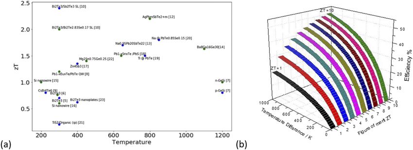
APL Materials                                                                               PERSPECTIVE              scitation.org/journal/apm

    forward, unconventional thinking with unconventional materials is          a lot of attention for the design of novel future TE material architec-
    called for.” Basically, progress has been held back because of the fact    tures and compositions to replace traditional semiconductors.
    that in conventional bulk thermoelectric materials, the quantities S,            Thermoelectric properties and relationships are subject to a few
    σ, and κ are interrelated in such a way as to make independent con-        laws of physics, which are indicated below; see Fig. 2. For example,
    trol of these variables to increase ZT almost impossible because an        the Mott relation establishes that the Seebeck coefficient S is indi-
    increase in S typically results in a decrease in σ and a decrease in       rectly proportional with the charge carrier density n. Therefore, very
    σ produces a decrease in the electronic contribution to κ, accord-         high Seebeck values are predicted for materials with an extremely
    ing to the Wiedemann–Franz law. The advent of nanotechnology               small charge carrier density n, such as in the case of quasi-insulators.
    with a combination of small size and higher efficiency enabled ther-       Merely increasing the electrical conductivity σ of a conventional
    moelectric applications that were unthinkable 20 years ago. Today,         thermoelectric material will not improve the ZT value because the
    thermoelectric generators (TEGs) can be just a couple of millimeters       Seebeck coefficient will drop due to its inverse proportionality with
    in size and less than a millimeter thick, yet they contain hundreds of     increased electrical conductivity according to the Mott relation. By
    thermocouples.                                                             increasing the electrical conductivity in traditional semiconductor
          By improving the ZT value with novel and non-traditional             (SC) thermoelectric materials, the electronic component of the ther-
    materials possessing very high theoretical ZT values, significant          mal conductivity will also proportionally increase according to the
    amounts of thermoelectric electricity can be generated from tem-           Wiedemann–Franz law. The Wiedemann–Franz law describes the
    perature differences of merely a few degrees; see Fig. 1(b). Modeling      relationship between electrical conductivity σ and the electronic
    results indicate that, with novel optimized materials and new fabri-       thermal conductivity κe by the Lorentz number Lo as follows: κe
    cation approaches, the power generation of thermoelectric devices          = Lo σT, e.g., in metals.18
    with power conversion efficiency exceeding 20% is feasible, which                The more electrically conductive the material is, the higher the
    significantly exceeds the state of the art, which is currently way below   charge carrier density n is, and the higher the resulting electronic
    12% for commercially available modules. Since ZT is inversely pro-         component of the thermal conductivity is. This trend is counter-
    portional to the thermal conductivity κ, it is imperative to decrease      productive to the improvement of ZT. These two laws of physics
    significantly the thermal conductivity and to decouple that change in      interrelate all relevant thermoelectric parameters in such a way as
    thermal conductivity κ from the Seebeck coefficient S and the elec-        to frustrate any significant improvement. As a consequence, the fig-
    trical conductivity σ. This objective can be achieved by localizing or     ure of merit (ZT) (see Fig. 1) has remained at a pretty constant
    trapping phonons within the materials. Novel materials with a very         level slightly above 1, which cannot be easily overcome by tradi-
    low thermal conductivity close to zero will attain unexpectedly high       tional bulk thermoelectric materials. The challenge is to optimize the
    ZT values. The higher the ZT values, the lower the required temper-        “power factor (PF),” the product of the Seebeck coefficient squared,
    ature gradient window. Traditional semiconductor (SC) materials            and electrical conductivity (=S2 σ) and to find the best trade-off for
    with lower ZT values are requiring much larger temperature win-            the composition of the ideal future MOF based hybrid thermo-
    dows to generate significant amounts of electricity. For this reason,      electric material. These trends have been established for the past
    the world requires novel nontraditional ZT materials and noth-             decades in the field without any real improvement. Therefore, con-
    ing less than the vision of revolutionary ultrahigh efficiency ther-       ventional bulk thermoelectric materials are simply “constrained”
    moelectric materials synthesized with completely new fabrication           by their physical laws, which cannot be easily overcome with bulk
    principles.                                                                materials, as indicated in Fig. 2. However, these issues and limita-
          Today, researchers are investigating flexible substrates, ther-      tions by the above quoted laws of physics are moot for materials
    moelectric fabrics, and low-cost materials. Progress in non-               with reduced dimensionality, such as quantum wells (QWs) (2D),
    traditional thermoelectric materials, such as MOF (Metal–Organic-          quantum wires (1D), and quantum dots (QDs) (0D), where the
    Framework) films (SURMOFs) and hybrid materials, could soon                introduction of a new variable (length scale) permits decoupling of
    lead to TEGs and cooling modules with higher efficiency suitable           the aforementioned parameters and allows them to be optimized
    for commercial applications.16 Soon we could have thermoelectric           simultaneously.
    foils or fibers directly woven into our clothing, which can utilize              The phonon glass electron crystal (PGEC) concept is used in
    heat directly, i.e., conversion of our body heat to power, for medical     modeling and is defined as a hypothetical material that possesses
    equipment such as pacemakers or electroosmotic pumps to deliver            the ideal low thermal conductivity of glass and optimum high elec-
    insulin and other drugs.17 Such embedded thermoelectric generators         trical conductivity of semiconducting crystals.20 The ideal PGEC
    will be able to cover large areas of our body or other arbitrary sur-      concept has served as a roadmap by pointing out that the general
    faces without detracting from the main function of fabrics—dressing        strategy of increasing the electrical conductivity and simultaneously
    people—and hardly be noticeable. The power generated in that fash-         decreasing the thermal conductivity of thermoelectric materials will
    ion could power sensors, actuators, smart watches, medical equip-          lead to the desired improvement in ZT values. Implementing this
    ment, or smartphones directly embedded in the garment without the          strategy accounts for the recent successes in improving inorganic
    need of physical recharging.17                                             thermoelectric materials. While the electrical conductivity of semi-
                                                                               conducting crystalline thermoelectric materials can be improved in
                                                                               a straightforward manner by highly doping the materials to enhance
    Moving forward, unconventional thinking
    with unconventional materials is called for                                the charge carrier density, this approach cannot easily be imple-
                                                                               mented into MOFs. Improving the electrical conductivity imposes
        From the perspective of next generation, novel advanced ther-          a special challenge to MOFs and requires novel strategies. However,
    moelectric materials improving the figure of merit (ZT) have gained        reducing the thermal conductivity by phonon scattering with porous

APL Mater. 8, 060902 (2020); doi: 10.1063/5.0004699                                                                                           8, 060902-3
© Author(s) 2020
APL Materials PERSPECTIVE scitation.org/journal/apm
FIG. 2. On the left, the basic laws of
physics governing thermoelectric rela-
tionships are shown. On the right,
schematic plots of the Seebeck coeffi-
cient S and the thermal conductivity κ
as a function of the natural logarithm
of charge carrier density n are shown,
adapted from Ref. 19.
templates works well in both inorganic thermoelectric materials of the order of magnitude of the mean-free path of phonons for that
and porous MOFs. Modeling of the phonon glass electron crystal material. Every time a phonon encounters a pore/hole, the phonon
(PGEC) concept revealed that successful reduction of thermal con- will be scattered and loses energy. Therefore, the simulation-based
ductivity can be realized in a cage-like “open structured” compound prediction of hierarchical and porous architectures plays a major
as a host crystal, where heavy mass atoms are trapped inside, act- role in the design of novel thermoelectric materials. The smaller the
ing as scattering centers of phonons, to reduce thermal conductiv- pores are, the more complex the porous structure or architecture is
ity. Experimentally, skutterudites and intermetallic clathrates come designed, and the more the phonon transport will be impeded across
very close to the ideal phonon glass electron crystals. Reduction of the structure/architecture lattice, and therefore, the Thermal Lattice
thermal conductivity is a universal key strategy for the enhance- Conductivity (TLC) will be highly reduced. To maximize the imped-
ment of ZT. Therefore, the two-pronged strategy of increasing elec- iment effect against phonon transport, the basic guiding principle
trical conductivity, while decreasing thermal conductivity, is valid stipulates that the pore dimensions should approximate the mean-
for inorganic and hybrid MOF materials but requires a different free path of the phonons in the respective material. Different models
implementation for optimizing the electrical conductivity due to have been reported21 in a porous “gray” material, as schematically
the chemo-physical properties of MOFs and coordination polymers depicted in Figs. 3(a) and 3(b). To illustrate the potential of the
(CPs). novel phonon engineering concept in nanostructured porous mate-
In the future, novel designs of porous hybrid materials and rials, the plots of Fig. 3(c) provide experimental examples of how
metal–organic materials have the potential to overcome some of the Seebeck coefficient S of the thermoelectric nanolaminate mate-
the constraints of physical laws that have handicapped conventional rial system PbTe/PbSe has been modulated by phonon engineering
semiconducting bulk thermoelectric materials. As these materials utilizing porous templates and porous membranes. Because of the
can be simulated and modeled by their composition, pore size, novelty aspect, there are hardly any literature reports on phonon
and physical properties, a new thermoelectric material design with engineering in porous MOF materials but have been reported for
unexpectedly high ZT values might be feasible in the near future. other inorganic thermoelectric systems. The potential benefits of
This could potentially lead to materials revolutionizing our energy phonon engineering in porous membranes have been theoretically
systems. modeled at MIT by the group of Romano.22,23 These theoretical
simulations have recently been verified experimentally with inor-
ganic thermoelectric materials.11,24–26 The plots in Fig. 3(c) bench-
The magic impact of working with “nanoscaled”
mark the Seebeck coefficient of the thermoelectric material sys-
pores in porous templates
tem PbTe/PbSe for the case of planar non-porous PbTe/PbSe films
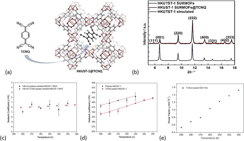
Pores/holes in porous templates constitute simply a “major vs the case of porous templates with successive higher pore den-
impediment for phonon transport,” especially if the pore dimension is sity.11 For PbTe/PbSe thermoelectric films on planar non-structured
APL Mater. 8, 060902 (2020); doi: 10.1063/5.0004699 8, 060902-4
© Author(s) 2020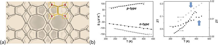
APL Materials                                                                                                   PERSPECTIVE                   scitation.org/journal/apm

      FIG. 3. (a) Schematic drawing of randomly oriented pores in a thermoelectric material. (b) Example of thermoelectric materials displaying different pore sizes, where the pores
      with the largest pore diameter have been infiltrated by super-positioned guest molecules. (c) Plots of the Seebeck coefficient of thermoelectric PbTe/PbSe films on the planar
      Si substrate benchmarked against PbTe/PbSe films on microporous Si substrates as a function of pore density and temperature. The nanostructured PbTe/PbSe films on the
      porous template with the highest pore density achieved a significant fourfold improvement for the Seebeck value,11 which illustrates the benefits of phonon engineering in
      porous material systems.

    Si substrates, the maximum Seebeck value measured was −143.02                               phonon transport, thereby creating a new generation of thermo-
    ± 5.5 μV/K at 300 K, while the thermoelectric films on the porous                           electric materials with ultra-low thermal conductivities or a heat
    Si substrate achieved an improved Seebeck value of −370.5 ± 37.7                            insulator with extremely low thermal conductivity. The optimum
    μV/K for an intermediate pore density. For the higher pore den-                             thermoelectric material is a material possessing almost no thermal
    sity, the Seebeck value increased further to −574.2 ± 20.8 μV/K at                          conductivity.
    300 K, which amounts to a fourfold improvement for the Seebeck
    coefficient compared to the planar non-structured Si substrate. This
    example demonstrates the advantages of phonon engineering for the
                                                                                                MATERIAL CHALLENGES
    thermoelectric material system PbTe/PbSe in porous Si templates
    achieving significant improvements in the Seebeck coefficient as a                               Porous hybrid materials and porous MOFs (Metal–Organic-
    function of pore density.11                                                                 Frameworks) and coordination polymers exhibit some promising
          Some authors in the literature claimed that a 3D cubic lattice                        material features that could predestine MOF and CNC (Coordi-
    with identical holes is not possible.20 However, 3D porous lattices are                     nation Network Compounds) films to be part of the next gen-
    feasible in MOFs and porous hybrid materials, which can be loaded                           eration of future thermoelectric materials. From the definition of
    even with guest molecules, thereby further reducing the thermal                             the IUPAC,27 coordination polymers can be described as repeating
    conductivity. Loading of pores by guest molecules will induce addi-                         coordination units with a 1D,28 2D,29 or 3D30 molecular structure.
    tional phonon scattering, caused by a superposition of the guests.                          In contrast, MOFs describe coordination networks with organic lig-
    Recently, this effect has been demonstrated experimentally. Inves-                          ands, which contain potential voids.31 In addition, the term MOF
    tigating these novel phenomena are part of the ongoing work in                              should also be exclusively used for carboxylate32 coordination net-
    progress in our laboratories. It is feasible to synthesize highly 3D                        works. Of course, there are material challenges; however, the devel-
    porous and hierarchical structures, which are designed to trap and                          opment pace and progress are fast and initial material issues appear
    to localize phonons within such structures or to severely impede                            manageable. High on the list of inherent advantages is the very

APL Mater. 8, 060902 (2020); doi: 10.1063/5.0004699                                                                                                                        8, 060902-5
© Author(s) 2020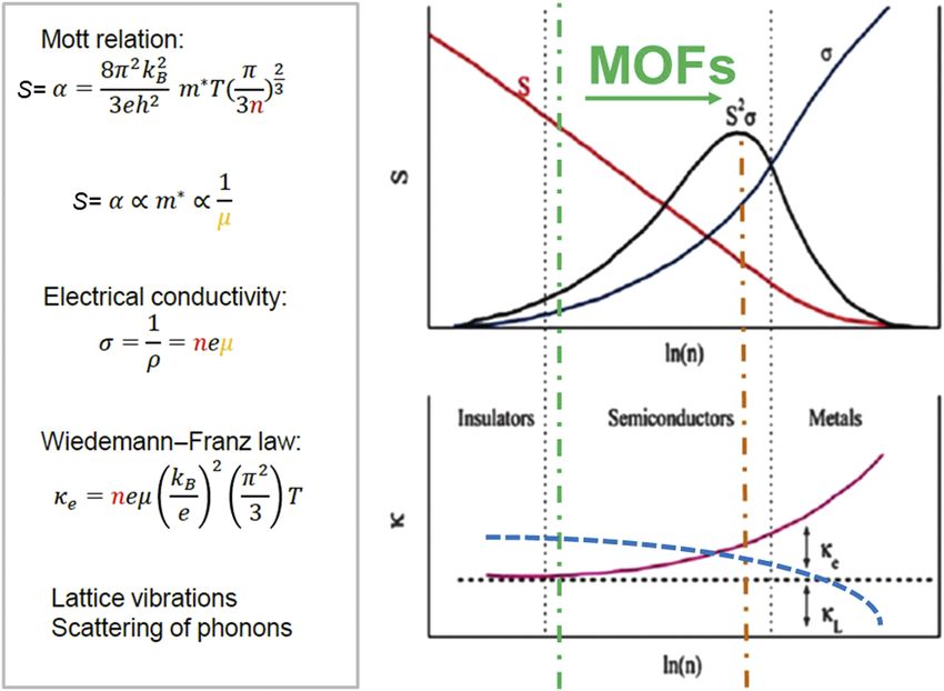
APL Materials                                                                                              PERSPECTIVE                  scitation.org/journal/apm

    high Seebeck coefficient33 and the possibility of designing optimized                   only in their powder form, e.g., as pressed pellets. In the follow-
    highly porous and complex hierarchical architectures.34 Drawbacks                       ing, we provide a short review of recent results of porous hybrid
    are still today the low electrical conductivity in many MOF sys-                        and MOF systems, which have been published in the field since last
    tems.35 However, just recently, a major scientific breakthrough in                      year.
    advanced MOFs/porous hybrid materials has been reported with
    metallic conductivity behavior at room temperature.36 Furthermore,                      HKUST-1@TCNQ loaded with TCNQ
    intrinsic and extrinsic defects control many properties in these
    materials ranging from nucleation, growth, and hetero-integration                             HKUST-1 MOF films (the acronym stands for Hong Kong
    to electronic and thermal transport. Defects in porous MOFs and                         University of Science and Technology) are constructed from Cu2+
    hybrid materials come in all shapes and sizes, from point defects                       dimers and benzene-tricarboxylate (BTC) units, which form a crys-
    such as vacancies and impurities and two-dimensional defects such                       talline, 3D porous structure with a pore diameter of 1.2 nm, where
    as grain boundaries. Therefore, all porous MOFs and hybrid mate-                        the available pores allow the loading or storage of guest molecules,
    rials contain structural defects that impact the physicochemical                        for example, TCNQ, inside the MOF structure [see Figs. 4(a) and
    properties of the porous MOF layers.37                                                  4(b)].
                                                                                                  It is rather obvious that the electrical properties of porous
                                                                                            MOFs/SURMOFs change when guest molecules are loaded into the
                                                                                            pores of the framework. The first studies of this type were reported
    OPPORTUNITIES—A BRIEF OVERVIEW
                                                                                            by Dragässer et al., for the case of loading ferrocene inside mono-
         Hybrid and MOF thin film architectures have been created by                        lithic HKUST-1 SURMOF thin films.38 Later, Talin et al. found that
    the combination of different coatings and/or growth techniques, e.g.,                   after loading TCNQ (tetracyanoquinodimethane) molecules into the
    through spin-coating, anodic oxidation/electrochemical methods,                         framework of HKUST-1, the electrical conductivity increased over
    liquid phase epitaxial (LPE) spray-coating, painting, dip-coating                       six orders of magnitude with values up to 7 S m−1 in air.39 First
    from suspensions, thin films sputtering, CVD, and liquid phase epi-                     models have suggested that the conductivity arises from redox-
    taxy (LPE). Regardless of the synthesis technique, most of them are                     active TCNQ guest molecules linking the copper paddle wheels
    based on a Layer by Layer (LbL) process, e.g., dip-coating, spin-                       within the open pores of HKUST-1.40 Charge transport between
    coating, or spraying. In the past, some materials have been studied                     the TCNQ guests has been recently described and theoretically

      FIG. 4. (a) Schematic drawing of TCNQ infiltrated HKUST-1. (b) XRD of pristine, TCNQ infiltrated, and simulated HKUST-1 thin films. Seebeck coefficient measurements on
      (c) highly oriented HKUST-1 thin films,43 (d) polycrystalline HKUST-1 thin films,42 and (e) power factor of TCNQ loaded HKUST-1 SURMOF.44

APL Mater. 8, 060902 (2020); doi: 10.1063/5.0004699                                                                                                                 8, 060902-6
© Author(s) 2020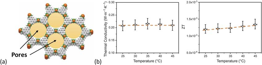
APL Materials                                                                                              PERSPECTIVE                  scitation.org/journal/apm

    investigated by a second-order process.41 In our own experimental                       of 8.31 × 10⁻³ W m−1 K−2 .45 In addition, the thermal conductiv-
    studies, it was also pointed out that inconsistencies exist between                     ity was also quite low with a value of around k = 0.21 W m−1 K−1 ,
    the electronic-conducting mechanism proposed by these authors                           where kL (lattice thermal conductivity) appears to be responsible
    and the experimentally established positive sign of the Seebeck-                        for the main contribution; see Fig. 5(b). These measured values
    coefficient, which is a clear indication of a p-type conducting mech-                   yielded an overall ZT of ≈1.25 × 10⁻³ at room temperature; see
    anism.42 Furthermore, we discovered that charge transfer and con-                       Fig. 5(b).45
    ductivity are highly anisotropic in MOF thin films. In this endeavor,
    we were be able to measure the Seebeck coefficient in polycrystalline                   Non-porous coordination polymers (CPs)
    samples but not in highly oriented HKUST-1 thin films; see also
    Fig. 4(c).43                                                                                  In contrast to porous MOFs, non-porous coordination
          Here, we have investigated the electrical properties of pristine                  polymers (CPs), such as poly[Cux (Cu-ethylenetetrathiolate)],46
    HKUST-1 and TCNQ loaded compact HKUST-1 SURMOF films                                    poly[Nax (Ni-ett)], and poly(Kx [Ni-ett]),47 should also be considered
    with Seebeck coefficient measurements.42 The compact MOF thin                           within the scope of this review; see Figs. 6(a)–6(c). These com-
    films were grown on pretreated Si substrates and on nonconductive                       pounds consist of repeating units of metal–organic complexes.46,47
    borosilicate substrates using liquid phase epitaxy (LPE) in conjunc-                    An entire series of this promising hybrid thermoelectric mate-
    tion with a spray process already reported in our previous stud-                        rial has been successfully synthesized. In fact, the CP poly(Kx [Ni-
    ies.42 This process yields MOF film thicknesses in the range of ≈40–                    ett]) is composed of Ni(II) ions, which are chemically bound to
    100 nm, depending on the number of spraying cycles used. SUR-                           1,1,2,2-ethenetetrathiolate (ett), where potassium K+ is used to bal-
    MOF films were characterized using x-ray diffraction and IRRAS                          ance the charge.47 However, for the present time, these coordina-
    measurements.                                                                           tion polymers hold the record for n-type coordination polymers
                                                                                            (CPs) with the highest ZT of around 0.2 at room temperature; see
                                                                                            Fig. 6(b).47
    MOG—Ni3 (HITP)2
                                                                                                  For poly[Cux (Cu-ethylenetetrathiolate)], the experimentally
         A significant increase in the ZT has been reported through lay-                    determined Seebeck coefficient rises as a function of increasing tem-
    ered Ni3 (2,3,6,7,10,11-hexaimino-triphenylene)2 [Ni3 (HITP)2 ].45                      perature, the positive Seebeck coefficient sign implies p-type charge
    These materials can be described as a layered 2D lattice composed                       carriers in the polymer, and the thermal conductivity also rises with
    of Ni2+ ions, which are connected to (HITP3− ) ligands, forming                         increasing temperature.46 At 300 K, the following details have been
    a honeycomb-like structure; see Fig. 5(a).45 The individual layers                      reported: the power factor PF and ZT are 4.17 W m−1 K−2 and 2.66
    are stacked, forming a graphite-like material, which are also known                     × 10−3 W m−1 K−2 , respectively, while the corresponding electri-
    as Molecular-Organic Graphene (MOG) with 1.5 nm-wide tubu-                              cal conductivity, Seebeck coefficient, and thermal conductivity have
    lar pores running parallel to the c-direction.45 Therefore, a high                      been reported as σ = 10.7 S cm−1 , S = 62.5 V K−1 , and κ = 0.47 W
    anisotropic electrical conductivity (σ) of ∼50 S cm−1 was reported at                   m−1 K−1 , respectively. At 400 K, the parameters reached the follow-
    room temperature, one of the highest among polycrystalline MOF                          ing values: (σ) 25.8 S cm−1 , (S) 77.5 V K−1 , and (κ) 0.57 W m−1 K−1 ,
    hybrid materials. This very high electrical conductivity also leads                     thereby resulting in a power factor PF of 15.5 W m−1 K−2 and a ZT
    to a 17-fold improvement of the ZT in comparison with HKUST-                            of 0.011.46 For the CP poly[Nax (Ni-ett)], ZT is 0.042 at 300 K and
    1@TCNQ systems.45                                                                       the ZT can reach up to 0.10 at 440 K. For all the reported coor-
         The material was characterized as pressed pellet powder with a                     dination polymers (CPs), it appears that the power factor PF and
    negative room temperature Seebeck coefficient (S) of −11.9 V K−1 ,                      the ZT tend to increase as a function of increasing temperature.
    describing an n-type conductivity semiconductor behavior.45 Fur-                        Furthermore, it has been reported that the ZT value of poly[Cux (Cu-
    thermore, the Seebeck coefficient S was shown to be quite constant                      ett)] varies between 0.002 and 0.014 in the temperature range from
    over the measured temperature range, yielding a power factor (PF)                       230 K to 400 K.46 This is the highest reported ZT value around

      FIG. 5. (a) Schematic drawing of layered porous Ni3 (2,3,6,7,10,11-hexaimino-triphenylene)2 [Ni3 (HITP)2 ] MOG adapted from Ref. 45. (b) Thermal conductivity and ZT of
      Ni3 (HITP)2 pressed powder pellets adapted with permission from Sun et al., Joule 1, 168 (2017). Copyright 2017 Elsevier.45

APL Mater. 8, 060902 (2020); doi: 10.1063/5.0004699                                                                                                                 8, 060902-7
© Author(s) 2020
APL Materials PERSPECTIVE scitation.org/journal/apm
FIG. 6. (a) Schematic drawing of non-porous coordination polymers (CPs) poly[Cux (Cu-ethylenetetrathiolate)] adapted from Ref. 46. (b) Seebeck coefficient and ZT of CPs
poly[Nax (Ni-ett)] and poly(Kx [Ni-ett]) adapted from Ref. 47.
0.014 (at 380 K), about one-order lower in comparison to that of coefficient (S) and the Power Factor (PF) have not been reported
nickel complexes poly[Nax (Ni-ett)] and poly[Kx (Ni-ett)]; see also in that study. Nanocomposites with an enhanced electrical conduc-
Fig. 6(b).47 tivity with lowered thermal conductivity are promising for novel
hybrid thermoelectric nanocomposite materials and thermoelectric
Polymer MOF based hybrid systems generator (TEG) applications.48
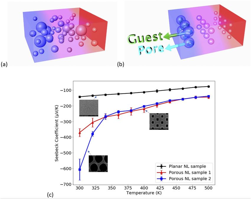
Recently, nanocomposites prepared from MOF films and con-
Screening platform: ZT chips form new
ducting polymers have been reported.48 The polymers such as
thermoelectric hybrid materials
polypyrrole (PPy) and poly3,4-ethylenedioxythiophene (PEDOT)
have been polymerized in situ in the voids of a UiO-66.48 The For screening purposes and in search for optimized future ther-
polymerization has been characterized by various analytical tech- moelectric porous hybrid and MOF materials, a complete in-plane
niques as well as HRTEM, revealing the successful incorporation electric and thermoelectric characterization was successfully applied
of polymer fibers inside the voids of the framework. Furthermore, to spin-coated conductive PEDOT:PSS organic thin films.49 To this
it was reported that in the polymerized UiO-66 composites, such end, a ZT lab-on-a-chip platform has been used; see Fig. 7(a) based
as UiO-66-PPy and UiO-66-PEDOT, the thermal conductivity (κ) on the Völklein geometry.50 By utilizing such a ZT test chip, the
was significantly reduced.48 The thermal conductivity for UiO-66 electrical conductivity (σ), the resistivity (ρ), the Seebeck coefficient
was determined as κ ≈ 0.8 W m−1 K−1 , which is significantly lower (S), the thermal conductivity (κ), the specific heat capacity (cp ), and,
in the case of UiO-66-PPy and UiO-66-PEDOT with values of κ consequently, the power factor (PF) and ZT values have been deter-
≈ 0.4 W m−1 K−1 and κ ≈ 0.3 W m−1 K−1 .48 However, the elec- mined simultaneously as a function of temperature with one single
trical conductivity was significantly increased by the incorporation measurement run; see Fig. 7(b).49 In addition, Hall measurements
of conductive polymers within the UiO-66 MOF.48 The Seebeck are possible with the same test chip design, which provides further
FIG. 7. (a) ZT test chip design for full electric and thermoelectric characterizations of conductive organic thin films adapted from Ref. 49. (b) Measured electrical and
thermal conductivity and Seebeck coefficient and calculated ZT value of a 15 μm PEDOT:PSS thin film within the temperature range 110–420 K. The 15 μm thick poly(3,4-
ethylenedioxythiophene) doped with a poly(styrene sulfonate) (PEDOT:PSS) film was prepared by drop casting.51
APL Mater. 8, 060902 (2020); doi: 10.1063/5.0004699 8, 060902-8
© Author(s) 2020APL Materials PERSPECTIVE scitation.org/journal/apm
8
details on the mobility (μ) as well as the charge carrier concentration D. Beretta, N. Neophytou, J. M. Hodges, M. G. Kanatzidis, D. Narducci,
(n) of the examined thermoelectric materials.49 M. Martin-Gonzalez, M. Beekman, B. Balke, G. Cerretti, W. Tremel, A. Zevalkink,
Such ZT test chip tools will be deployed to efficiently test and A. I. Hofmann, C. Müller, B. Dörling, M. Campoy-Quiles, and M. Caironi, Mater.
Sci. Eng., R 138, 100501 (2019).
prescreen which porous hybrid materials or MOF film composition 9
L. F. Llin and D. J. Paul, in ICT—Energy Concepts for Energy Efficiency and
possess the requisite properties for further material optimization Sustainability (InTechOpen, 2017), Chap. 9.
toward real device applications.49 The application potential includes 10
Z.-G. Chen, G. Han, L. Yang, L. Cheng, and J. Zou, Prog. Nat. Sci.: Mater. Int.
custom designed thermoelectric thin film generators powered solely 22, 535 (2012).
by the use of human body heat. 11
X. Chen, P. Lin, K. Zhang, H. Baumgart, B. Geist, and V. Kochergin, ECS J. Solid
State Sci. Technol. 5(9), P503–P508 (2016).
12
E. Altenkirch, “Über den nutzeffekt der thermosäule,” Phys. Z. 10, 560
LOOKING FORWARD—FUTURE OUTLOOK ON NOVEL (1909).
THERMOELECTRIC MATERIALS 13
A. F. Ioffe, L. S. Stil’bans, E. K. Iordanishvili, T. S. Stavitskaya, and A. Gelbtuch,
Phys. Today 12(5), 42 (1959).
Thermoelectric materials based on porous hybrid and MOFs 14
J. Mao, Z. Liu, and Z. Ren, “Size effect in thermoelectric materials,” npj
constitute a very recent development, with many new and undis- Quantum Mater. 1, 16028 (2016).
covered phenomena for the research field. It is anticipated that 15
D. M. Rowe, Thermoelectrics Handbook: Macro to Nano (Taylor & Francis Ltd.,
especially the inherent porosity can be used advantageously in the 2006), pp. 54–112.
design and simulation predictions of future thermoelectric mate- 16
H. Jin, J. Li, J. Iocozzia, X. Zeng, P. C. Wei, C. Yang, N. Li, Z. Liu, H. He, T. Zhu,
rials. In principle, porous hybrid and MOF materials can comply J. Wang, Z. Lin, and S. Wang, Angew. Chem., Int. Ed. 58, 15206 (2019).
17
with most of the requirements of an ideal and tunable future ther- M. Culebras, C. M. Gómez, and A. Cantarero, Materials 7, 6701 (2014).
18
moelectric (TE) material. In contrast to traditional inorganic semi- F. Völklein, H. Reith, T. W. Cornelius, M. Rauber, and R. Neumann, Nanotech-
conductor (SC) materials, porous hybrid materials and MOFs have nology 20, 325706 (2009).
19
C. Wood, “Materials for thermoelectric energy conversion,” Rep. Prog. Phys.
been demonstrated to be able to overcome the laws of physics gov-
51, 459 (1988).
erning bulk thermoelectric materials. These classes of novel materi- 20
G. A. Slack, “Design concepts for improved thermoelectric materials,” in MRS
als offer new approaches to the design of complex and hierarchical Online Proceedings Library Archive (Cambridge University Press, Cambridge, UK,
porous structures, possessing ultra-low thermal conductivity, which 1997), Vol. 478.
are able to trap and localize phonons, thus resulting in a new gen- 21
R. H. Tarkhanyan and D. G. Niarchos, APL Mater. 2, 076107 (2014).
eration of thermoelectric materials with a high ZT (figure of merit) 22
G. Romano, A. Di Carlo, and J. C. Grossman, J. Comput. Electron. 11(1), 8
number. (2012).
23
Therefore, as there are hardly any upper limits on the fig- G. Romano and J. C. Grossman, Appl. Phys. Lett. 105(3), 033116 (2014).
24
ure of merit (ZT), the quest for new and unexplored novel future M. Nomura, Y. Kage, J. Nakagawa, T. Hori, J. Maire, J. Shiomi, R. Anufriev,
thermoelectric materials is on. D. Moser, and O. Paul, Phys. Rev. B 91(20), 205422 (2015).
25
M. Nomura, Y. Kage, D. Müller, D. Moser, and O. Paul, Appl. Phys. Lett.
This work demonstrates recent results of MOF TE materials
106(22), 223106 (2015).
and provides a vision and a future outlook for the search for tomor- 26
X. Chen and H. Baumgart, Materials 13, 1283 (2020).
row’s novel thermoelectric MOF materials, which could be part of an 27
S. R. Batten, N. R. Champness, X.-M. Chen, J. Garcia-Martinez, S. Kitagawa,
anticipated green sustainable energy revolution with novel materials L. Öhrström, M. O’Keeffe, M. Paik Suh, and J. Reedijk, Pure Appl. Chem. 85, 1715
of high ZT values. (2013).
28
F. Kübel and J. Strähle, Z. Naturforsch., B 37, 272 (1982).
29
D. Venkataraman, S. Lee, J. S. Moore, P. Zhang, K. A. Hirsch, G. B. Gardner,
ACKNOWLEDGMENTS A. C. Covey, and C. L. Prentice, Chem. Mater. 8, 2030 (1996).
30
E.R. acknowledges financial support by the Deutsche B. F. Abrahams, M. J. Hardie, B. F. Hoskins, R. Robson, and E. E. Sutherland,
J. Chem. Soc., Chem. Commun. 1994, 1049.
Forschungsgemeinschaft (DFG) within the Priority Program 31
H. Li, M. Eddaoudi, M. O’Keeffe, and O. M. Yaghi, Nature 402, 276 (1999).
COORNET (Grant No. SPP 1928). H.B. acknowledges financial help 32
S. S. Y. Chui, S. M. F. Lo, J. P. H. Charmant, A. G. Orpen, and I. D. Williams,
from Old Dominion University. The authors would like to thank Science 283, 1148 (1999).
Donghui Chen for designing the images in Figs. 3(a) and 3(b). 33
K. J. Erickson, F. Léonard, V. Stavila, M. E. Foster, C. D. Spataru, R. E. Jones,
B. M. Foley, P. E. Hopkins, M. D. Allendorf, and A. A. Talin, Adv. Mater. 27, 3453
(2015).
REFERENCES 34
D. H. Chen, R. Haldar, B. L. Neumeier, Z. H. Fu, C. Feldmann, C. Wöll, and
1
D. M. Rowe, Thermoelectrics Handbook: Macro to Nano (Taylor & Francis Ltd., E. Redel, Adv. Funct. Mat. 29, 1903086 (2019).
35
2006), pp. 1–23. A. A. Talin, R. E. Jones, and P. E. Hopkins, MRS Bull. 41(11), 877–882
2
T. J. Seebeck, Magnetic Polarization of Metals and Ores by Temperature Differ- (2016).
36
ences (Abhandlungen der Königlichen Akademie der Wissenschaften zu, Berlin, R. Dong, P. Han, H. Arora, M. Ballabio, M. Karakus, Z. Zhang, C. Shekhar,
1822), pp. 265–373. P. Adler, P. S. Petkov, A. Erbe, S. C. B. Mannsfeld, C. Felser, T. Heine, M. Bonn,
3
F. J. DiSalvo, Science 285, 703 (1999). X. Feng, and E. Cánovas, Nat. Mater. 17, 1027 (2018).
4 37
P. M. Peltier, Ann. Chim. Phys. 56, 371 (1834). J. Liu and C. Wöll, Chem. Soc. Rev. 46, 5730 (2017).
5 38
W. Thomson, “On a mechanical theory of thermo-electric currents,” Proc. R. A. Dragässer, O. Shekhah, O. Zybaylo, C. Shen, M. Buck, C. Wöll, and D. Schlet-
Soc. Edinburgh 3, 91–98 (1851). twein, Chem. Commun. 48, 663 (2012).
6 39
R. He, G. Schierning, and K. Nielsch, Adv. Mater. Technol. 3, 1700256 (2018). A. A. Talin, A. Centrone, A. C. Ford, M. E. Foster, V. Stavila, P. Haney, R. A.
7
C. J. Vineis, A. Shakouri, A. Majumdar, and M. G. Kanatzidis, Adv. Mater. 22, Kinney, V. Szalai, F. El Gabaly, H. P. Yoon et al., Science 343, 66 (2014).
40
3970 (2010). V. Stavila, A. A. Talin, and M. D. Allendorf, Chem. Soc. Rev. 43, 5994 (2014).
APL Mater. 8, 060902 (2020); doi: 10.1063/5.0004699 8, 060902-9
© Author(s) 2020APL Materials PERSPECTIVE scitation.org/journal/apm
41 46
T. Neumann, J. Liu, T. Wächter, P. Friederich, F. Symalla, A. Welle, V. P. Sheng, Y. Sun, F. Jiao, C. Liu, W. Xu, and D. Zhu, Synth. Met. 188, 111
Mugnaini, V. Meded, M. Zharnikov, C. Wöll, and W. Wenzel, ACS Nano 10, 7085 (2014).
(2016). 47
Y. Sun, P. Sheng, C. Di, F. Jiao, D. Qiu, and D. Zhu, Adv. Mater. 24, 932
42
X. Chen, Z. Wang, Z. M. Hassan, P. Lin, K. Zhang, H. Baumgart, and E. Redel, (2012).
48
ECS J. Solid State Sci. Technol. 6, P150 (2017). A. Jadhav, K. Gupta, P. Ninawe, and N. Ballav, Angew. Chem., Int. Ed. 59, 2215
43
X. Chen, Z. Wang, P. Lin, K. Zhang, H. Baumgart, E. Redel, and C. Wöll, ECS (2020).
49
Trans. 75, 119 (2016). V. Linseis, Z. M. Hassan, H. Reith, J. Garcia, K. Nielsch, H. Baumgart, E. Redel,
44
X. Chen and H. Baumgart, private communication (2017). and P. Woias, Phys. Status Solidi A 215, 1700930 (2018).
45 50
L. Sun, B. Liao, D. Sheberla, D. Kraemer, J. Zhou, E. A. Stach, D. Zakharov, V. Linseis, F. Völklein, H. Reith, P. Woias, and K. Nielsch, J. Mater. Res. 31,
V. Stavila, A. A. Talin, Y. Ge, M. D. Allendorf, G. Chen, F. Leonard, and M. Dincă, 3196 (2016).
51
Joule 1, 168 (2017). V. Linseis, Linseis Company, private communication (2018).
APL Mater. 8, 060902 (2020); doi: 10.1063/5.0004699 8, 060902-10
© Author(s) 2020You can also read