Enhanced condensation heat transfer using porous silica inverse opal coatings on copper tubes
←
→
Page content transcription
If your browser does not render page correctly, please read the page content below
www.nature.com/scientificreports
OPEN Enhanced condensation heat
transfer using porous silica inverse
opal coatings on copper tubes
Solomon Adera1,2,3*, Lauren Naworski1, Alana Davitt1, Nikolaj K. Mandsberg1,5,
Anna V. Shneidman1, Jack Alvarenga1 & Joanna Aizenberg1,2,4*
Phase-change condensation is commonplace in nature and industry. Since the 1930s, it is well
understood that vapor condenses in filmwise mode on clean metallic surfaces whereas it condenses
by forming discrete droplets on surfaces coated with a promoter material. In both filmwise and
dropwise modes, the condensate is removed when gravity overcomes pinning forces. In this work,
we show rapid condensate transport through cracks that formed due to material shrinkage when a
copper tube is coated with silica inverse opal structures. Importantly, the high hydraulic conductivity
of the cracks promote axial condensate transport that is beneficial for condensation heat transfer.
In our experiments, the cracks improved the heat transfer coefficient from ≈ 12 kW/m2 K for laminar
filmwise condensation on smooth clean copper tubes to ≈ 80 kW/m2 K for inverse opal coated copper
tubes; nearly a sevenfold increase from filmwise condensation and identical enhancement with
state-of-the-art dropwise condensation. Furthermore, our results show that impregnating the porous
structure with oil further improves the heat transfer coefficient by an additional 30% to ≈ 103 kW/
m2 K. Importantly, compared to the fast-degrading dropwise condensation, the inverse opal coated
copper tubes maintained high heat transfer rates when the experiments were repeated > 20 times;
each experiment lasting 3–4 h. In addition to the new coating approach, the insights gained from this
work present a strategy to minimize oil depletion during condensation from lubricated surfaces.
Vapor-to-liquid phase change condensation is routinely observed in numerous industrial p rocesses1–11. For
example, in fossil-fueled or coal-fired steam power plants, the low pressure steam that exits the turbine enters a
condenser unit and changes its phase to liquid. In a similar fashion, distillation towers sequentially liquefy vapor
mixtures into various component liquid hydrocarbons by employing a condenser. The distilled hydrocarbons
are later used as energy sources for powering various industries including land, sea, and air transportation.
Desalination12 is another example that gained traction in recent years due to increased concerns of global water
scarcity13. The widely used multi-stage flash desalination p lants5 employ condensers to produce potable water
by condensing the vapor that is generated from saltwater (brine). Condensation is equally important in nature.
It is observed when plant leaves collect dew in the early morning hours of the summer or when fog forms on
windowpanes on humid days. Condensation processes require that the enthalpy of phase change be removed by
the working fluid. Compared to other working fluids, water has a significantly higher enthalpy of phase change
(2.257 MJ/kg at 373.15 K and 1 atm)14,15. Due to its impact in power and process engineering16–20, condensation
is still an active area of research in spite of its long history that spans over a century.
Phase-change condensation commences when the wall temperature of a surface is decreased below the satura-
tion temperature. In a pure vapor environment where noncondensable gases (NCG) are absent21–28 the required
subcooling (the degree to which the condenser surface is cooled relative to the surrounding vapor) to initiate
condensation is low. NCGs are non-target species such as oxygen and nitrogen gases that do not condense or
liquefy at the saturation temperature of water vapor (100 °C at 1 atm). Instead, NCGs, which are driven along
with the target species to the liquid–vapor interface due to convection, accumulate near the condensing surface
and create a diffusion barrier for phase change condensation26. Consequently, when the vapor mixture contains
1
John A. Paulson School of Engineering and Applied Sciences, Harvard University, Cambridge,
Massachusetts 02138, USA. 2Wyss Institute for Biologically Inspired Engineering, Harvard University, Cambridge,
Massachusetts 02138, USA. 3Department of Mechanical Engineering, University of Michigan, Ann Arbor,
Michigan 48109, USA. 4Department of Chemistry and Chemical Biology, Harvard University, Cambridge,
Massachusetts 02138, USA. 5Department of Health Technology, Technical University of Denmark, 2800 Kongens
Lyngby, Denmark. *email: sadera@umich.edu; jaiz@seas.harvard.edu
Scientific Reports | (2021) 11:10675 | https://doi.org/10.1038/s41598-021-90015-x 1
Vol.:(0123456789)
www.nature.com/scientificreports/
Figure 1. Schematic depictions of different modes of condensation. (a) Filmwise condensation (FWC) where
the condensate forms a continuous liquid film on a chemically clean (high surface energy) surface. The wall
is maintained at a lower temperature (Tw ) than the surrounding saturated vapor (Tsat). The temperature and
velocity profiles are shown for laminar film condensation where the flow-rate based Reynolds number is < 30.
(b) Dropwise condensation (DWC) on hydrophobic (low surface energy) surface. It is essential for dropwise
condensation that some promoter material, for example organic compound, be present on the surface.
Periodic removal of large droplets clears the surface for renewed droplet nucleation and growth. (c) Inverse
opal condensation (IOC) on a porous inverse opal structure. Condensate seeps into the porous structure by
displacing the air in the pores. Preferential condensate transport through high hydraulic conductivity micro
cracks improves the heat transfer rate. (d) Condensation on a slippery liquid-infused porous surface (SLIPS).
The porous interstices are impregnated with a chemically matched oil. Compared to DWC, droplets depart with
smaller radius and higher frequency in SLIPS condensation.
not only the condensing species but also one or more NCGs, the phase change heat transfer coefficient is signifi-
cantly lower than when the NCGs are absent. In the presence of NCGs, the condensation rate is lower because the
condensing species must first diffuse through the concentration boundary layer that coats the vapor side of the
interface. The condensing species must first overcome the mass transfer resistance posed by the concentration
boundary layer created by accumulation of gases near the liquid–vapor interface29.
There are two clearly distinguishable ideal modes of condensation of water vapor on cold metallic surfaces,
namely, filmwise condensation (FWC)-when the condensed vapor is distributed as a continuous liquid film with
characteristic thickness ≈ 100 μm (Fig. 1a), and dropwise condensation (DWC)-when the condensate liquid is in
the form of discrete droplets (Fig. 1b). A series of publications in 1934 and 1935 by Nagle et al.30–33 established
that pure steam condensing on a chemically clean surface always forms a continuous film and that the presence
of impurities which render the surface nonwetting is essential for the formation of discrete droplets. Since then,
it is well understood that FWC occurs on high surface energy metallic surfaces and their o xides34–36. Whereas
DWC occurs when the surface is coated with a promoter material (for example, chemical treatment with a hydro-
phobic silane or fluorocarbon)37–40. In the design of condensers, the function of which is to cool a vapor stream
in order to convert it to liquid phase, there is a great incentive to promote the breakup of the condensate film into
discrete droplets. Numerous studies have demonstrated that phase-change heat transfer during DWC is nearly an
order of magnitude higher than FWC in a pure vapor environment since in the latter mode of condensation, the
continuous liquid film increases the overall thermal resistance by adding a conduction resistance. In both FWC
and DWC, condensate liquid is drained vertically when gravity overcomes pinning forces. For DWC, this occurs
when the drop radius becomes comparable to the capillary length of water (≈ 2.7 mm at 25 °C and 1 atm). The
periodic surface clearing and sweeping action performed by the large droplets renews finite-size regions of the
surface for restart of the time-dependent condensation process, thereby reactivating nucleation sites to improve
the overall condensation heat transfer.
Unfortunately, the promoter materials or hydrophobic coatings that are commonly used for DWC have
proven to have finite lifetime. They wear off rather quickly due to viscous drag or friction exerted on the coating
by the sweeping action of the droplet. Depending on the working condition inside the condenser, the perfor-
mance benefits of hydrophobic coatings could last only few h ours37,41. Especially under harsh industrial working
conditions (for example, pressurized superheated steam), promoters can breakdown with minor impurities in
the steam or due to erosion by water droplets. For example, Hampson and O zisiks41 showed that a brass surface
treated with oleic acid exhibits dropwise condensation of saturated steam for only ≈ 3 h. Industrial condenser
surfaces, however, are required to last longer than what has been demonstrated thus far using surface treat-
ment techniques. Much research has been devoted in understanding the time interval during which promoter
Scientific Reports | (2021) 11:10675 | https://doi.org/10.1038/s41598-021-90015-x 2
Vol:.(1234567890)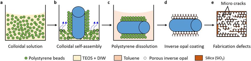
www.nature.com/scientificreports/
Figure 2. Schematic depiction of the fabrication procedure to produce inverse-opal-coated copper tubes.
(a) Colloidal solution is prepared by adding 0.5 wt% colloidal polystyrene particles (395 nm diameter) into a
solution of 99.4 wt% deionized water and 0.1 wt% tetraethyl orthosilicate (TEOS). (b) A copper tube coated
with silica via atomic layer deposition (ALD) and oxygen plasma cleaned is inserted vertically in the colloidal
solution to allow colloidal self-assembly as the solution evaporates. (c) The polystyrene beads are dissolved by
immersing the copper tube in toluene. (d) A porous inverse opal structure composed of a network of voids is
created when the sacrificial polystyrene beads dissolve in toluene. (e) During the drying stage, interconnected
micro cracks featuring large hydraulic conductivity form between islands of inverse opals.
coatings remain effective. The manner of their breakdown in industrial conditions has since been undertaken
with the aim to produce long-lived or near permanent dropwise condensation. Thick hydrophobic coatings can
mitigate the problem of wear-and-tear. But simply increasing coating thickness is generally not favorable since
such an approach increases the overall conduction resistance. Prior studies have shown that due to the increase
in conduction resistance, hydrophobic coatings in excess of 20 μm tend to offset the heat transfer augmentation
effect obtained from DWC. Despite numerous studies since it was first reported in the 1 930s42, creating durable
hydrophobic coatings for DWC is still a challenge that is not resolved to date.
In this work, we demonstrate a different approach that does not require a chemical functionalization with a
hydrophobic coating. We create a porous silica structure known as an inverse opal to allow vapor to condense
in its energy favorable state as shown in Fig. 1c. The condensate liquid that instantaneously spreads and seeps
into the porous structure is transported away from the surface through micro cracks that arise naturally dur-
ing the fabrication process. Due to the hydrophilic nature of the substrate and inner pore surfaces, these cracks
have high hydraulic conductivity (low flow resistance) that favors rapid preferential condensate transport in the
axial direction that is beneficial for phase change. Hereinafter, we refer this mode of condensation as inverse
opal condensation (IOC). This material design provides a durable solution by eliminating the need for a pro-
moter coating. The concept of actively controlling the thickness of the condensate film using porous structures
has been reported in previous s tudies43–48. The current work validates the concept by conducting heat transfer
measurements, through which we show that the porous inverse opal coatings on copper tubes show comparable
heat transfer rates to state-of-the-art hydrophobic-coated surfaces for DWC, a sevenfold increase compared to
surfaces exhibiting FWC. Furthermore, we chemically functionalized and impregnated the porous structure with
a lubrication film to create slippery liquid-infused porous surfaces (SLIPS) for condensation, shown schematically
in Fig. 1d. Droplet shedding was facilitated significantly (i.e., faster droplet shedding at smaller length scale and
higher frequency compared to those in DWC). Due to improved droplet mobility, the vapor-side heat transfer
rate was improved further in SLIPS condensation compared to both DWC and IOC. The insights gained from
this work present an opportunity to solve one of the long-standing durability concerns of modern condenser
surface coatings.
Sample fabrication. Using a bottom-up colloidal co-assembly technique49–51, we coated a copper tube
(length = 60 mm, external diameter = 6.35 mm, internal diameter = 4.57 mm) with inverse opal structures, a
highly porous material coating consisting of sub-micron voids in a support matrix, here silica. In brief, the cop-
per tube is wet-cleaned using solvents (acetone, ethanol, isopropanol, and deionized water sequentially) and a
thin (≈ 4 nm) layer of silica is deposited on the surface using atomic layer deposition (ALD). Additional wet-
cleaning and oxygen plasma cleaning are performed in order to facilitate wetting of the colloidal solution and
subsequent self-assembly on the copper surface. The clean silica-coated copper tube is immersed in a colloidal
solution consisting of templating polystyrene beads together with tetraethyl orthosilicate (TEOS), the precursor
for the background matrix, as shown in Fig. 2a. The colloids self-assemble into a face-centered cubic lattice (fcc)
as the solution evaporates (Fig. 2b) with hydrolyzed TEOS forming a silica network in the interstitials between
the assembled spheres. The polystyrene beads are then dissolved in toluene (Fig. 2c) resulting in a porous silica
coating (Fig. 2d). During the drying stage, fabrication defects arise in the form of interconnected micro cracks
between islands of inverse opals as shown in top-down schematic view of the porous inverse opal structure
(Fig. 2e). See “Materials and methods” for more details regarding material synthesis and fabrication.
Typical scanning electron micrograph (SEM) images of the porous silica inverse opal coating at different
magnifications are presented in Fig. 3a–d. During co-assembly of the polystyrene beads (≈ 395 nm diameter),
the contact area that remained dry (i.e., without being wetted by the solution) resulted in interconnected network
of holes/voids (≈ 215 nm diameter) as shown in Fig. 3d. Since silicon dioxide is intrinsically h ydrophilic52, the
resulting inverse opal coating is superhydrophilic and a millimeter size water droplet spreads with vanishing
Scientific Reports | (2021) 11:10675 | https://doi.org/10.1038/s41598-021-90015-x 3
Vol.:(0123456789)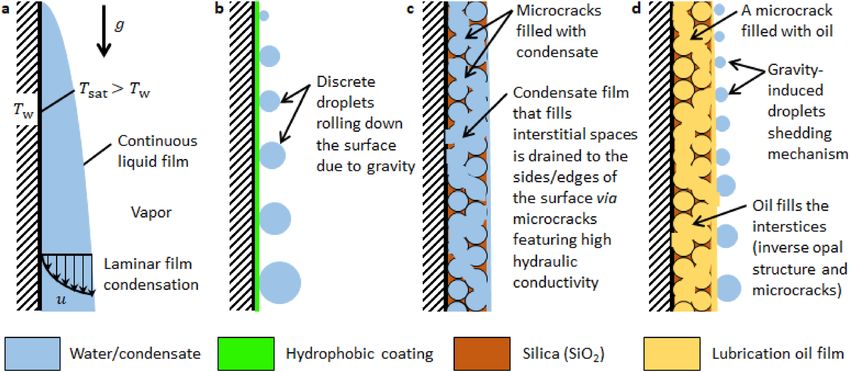
www.nature.com/scientificreports/

                                            Figure 3.  Scanning electron microscope (SEM) images of an inverse opal coating at different magnifications.
                                            The low magnification SEM images in (a) and (b) show fabrication defects (cracks) that formed when the
                                            supporting matrix shrank during drying. The inset in (a) shows a vanishing contact angle for a water droplet
                                            deposited on the porous structure. The high magnification images in (c) and (d) show the pores which resulted
                                            from dissolution of the sacrificial polystyrene beads (≈ 395 nm diameter). The contact points between the
                                            polystyrene beads that was not wetted by the solution during co-assembly created interconnected pores
                                            (≈ 215 nm diameter).

                                            apparent contact angle (θapp) as shown by the inset in Fig. 3a. Material shrinkage-induced cracks formed between
                                            islands of inverse opals (Fig. 3a,b). Surface wettability studies (Fig. S1) and additional SEM images including post
                                            condensation SEM characterization (Fig. S2) are provided in Supporting Material Section S1.
                                                Based on the SEM measurements, the typical thickness of the inverse opal coating is ≈ 8–12 μm.. Looking at
                                            the fluidic transport mechanism, small coating thickness gives rise to larger flow/viscous resistance. Inversely,
                                            increasing the coating thickness increases the conduction resistance for heat transfer. Consequently, both of these
                                            effects (i.e., coupled momentum and energy equations) need to be considered to optimize coating thickness for
                                            condensation, which can be achieved in the assembly process. For example, the size of the beaker containing
                                            the copper tube can be increased to reduce the influence of the beaker walls and thus reduce the thickness. To
                                            increase the thickness, multiple colloidal assembly steps can be performed in sequence.

                                            Results and discussion
                                            We built an experimental setup to measure the heat transfer rate and visualize droplet nucleation, growth, and
                                            departure. The main components are an environmental chamber, vapor generator, and cooling system (Fig. 4).
                                            In addition to maintaining the chamber at saturated conditions (saturated temperature at the corresponding
                                            pressure), the custom-made stainless steel environmental chamber is designed to eliminate non-condensing gases
                                            from the system. The chamber is externally insulated using low thermal conductivity fiberglass sheet (9333K71,
                                            McMaster-Carr) to reduce heat loss to the surrounding environment. During the experiment, the chamber walls
                                            were heated slightly above the saturation temperature by turning on a rope heater that is wrapped around the
                                            chamber under the insulation. This was necessary to prevent droplet condensation on the internal walls of the
                                            chamber which can potentially interfere with visualization. Images of droplet nucleation, growth, and departure
                                            were captured at 0.2 frames per second (fps) using a DSLR camera. Details of the environmental chamber and

          Scientific Reports |   (2021) 11:10675 |               https://doi.org/10.1038/s41598-021-90015-x                                                   4

Vol:.(1234567890)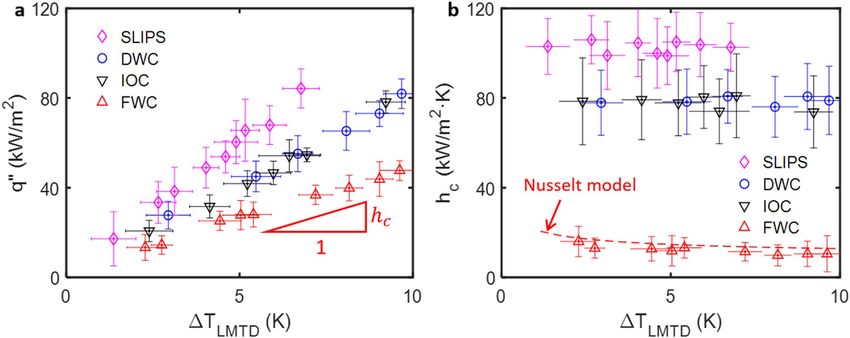
www.nature.com/scientificreports/

                                  Figure 4.  Schematic of the experimental setup constructed for phase change condensation study. The
                                  environmental chamber maintains saturation condition by eliminating NCGs from the system. The vapor
                                  that enters the chamber condenses on the copper tube that is maintained below the saturation temperature
                                  by circulating chilled water from a water bath heat exchanger. To minimize heat loss to the surrounding
                                  environment, both the chamber and the vapor generator are insulated using a fiberglass sheet. The chamber has
                                  a view port to observe droplet nucleation, growth, and departure.

                                  associated instrumentation is discussed in Supporting Material Section S2, Fig. S3. Additionally, typical images
                                  showing the different modes of condensation is given in Fig. S4 (Supporting Material Section S2).
                                      In preparation for the experiment, the water in the vapor generator was degassed via vigorous boiling. The
                                  degassed water in the vapor generator was maintained at saturated conditions at ≈ 85 °C and ≈ 58 kPa. After
                                  attaching the coated copper tube to the cooling water circulation line, the entire system was evacuated using a
                                  roughing pump to remove NCGs. The absence of NCGs was confirmed by matching the chamber saturation
                                  temperature with the corresponding saturation pressure. During the experiment, hot steam (vapor) was allowed
                                  to enter the chamber from the vapor generator by slowly opening a needle valve. Vapor inlet was controlled to
                                  allow saturation conditions inside the chamber. The copper tube was maintained below the chamber saturation
                                  temperature by circulating chilled water whose inlet and outlet temperatures were measured using calibrated
                                  thermocouples as shown in Fig. S5 (Supporting Material Section S3). For reliable heat transfer measurements,
                                  a 0.2–2.5 °C temperature difference was maintained between incoming and outgoing cooling water by control-
                                  ling the flow rate of the coolant. In addition to the temperature of the working fluid, the wet-bulb and dry-bulb
                                  temperatures of the chamber, flow rate, and chamber pressure were measured and recorded using a data acquisi-
                                  tion system.
                                      Different modes of condensation ensue depending on the type of the surface coating (Fig. 5). When the
                                  smooth copper tube was oxygen plasma treated, steam condensed by forming a continuous liquid film (Fig. 5a).
                                  The condensate film shown by the arrow at t = 0 s grew large and sheds due to gravity at t = 20 s. When the
                                  smooth copper tube was hydrophobized via silane treatment (trichloro(1H,1H,2H,2H-perfluorooctyl)silane,
                                  Sigma Aldrich), vapor condensed by forming discrete water droplets (arrow, t = 0 s, Fig. 5b). Condensate drop-
                                  lets detached when their radius reached the capillary length (≈ 2.7 mm for water). In both the filmwise mode
                                  (Fig. 5a) and dropwise mode (Fig. 5b), condensate was drained vertically due to gravity. Additional images are
                                  available in Fig. S4 (Supporting Material).
                                      When the copper tube was coated with porous silica inverse opals, the condensate seeped into the inter-
                                  connected pores since both the underlying substrate (silica-coated copper) and silica inverse opal matrix are
                                  inherently hydrophilic. Importantly, the condensate was transported rapidly in the axial direction through the
                                  interconnected cracks to the ends of the tube. The droplet shown by the arrow in Fig. 5c (t = 10 s) moved to the
                                  left (t = 20 s) even though we observed condensate transport to the right or to the left depending on the dimen-
                                  sion, geometry and orientation of the cracks. We attribute the axial transport to the high hydraulic conductivity
                                  of the cracks when compared to the interstitial pores. This condensate transport mechanism is distinctively dif-
                                  ferent from FWC (Fig. 5a) and DWC (Fig. 5b) wherein the condensate film is drained vertically due to gravity.
                                      The droplet shedding mechanism reported recently by Anderson et al.53 is also different from our observation.
                                  Here the coating has homogeneous wettability (due to the superhydrophilic character of the inverse opal coating)
                                  whereas Anderson et al.53 used biphilic surfaces (hydrophilic base with hydrophobic tips) to connect nucleat-
                                  ing droplets via liquid bridges. When the inverse opal structure was chemically functionalized with silane and
                                  impregnated with silicone oil (100 cSt at 25 °C, Sigma Aldrich), vapor condensed by forming highly mobile water
                                  droplets that depart at smaller length scale (Fig. 5d). Compared to the classical DWC, prior studies have shown

Scientific Reports |   (2021) 11:10675 |              https://doi.org/10.1038/s41598-021-90015-x                                                  5

                                                                                                                                            Vol.:(0123456789)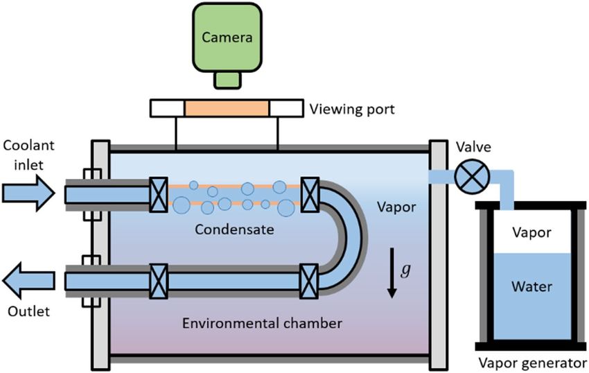
www.nature.com/scientificreports/
Figure 5. Time-lapse images of water condensation on copper tubes subject to varying surface treatments,
showing different modes of condensation. (a) FWC on a smooth plasma treated copper tube, (b) DWC
on smooth hydrophobized copper tube, (c) IOC on silica inverse opal-coated copper tube, and (d) SLIPS
condensation on oil-impregnated porous structure. In all cases except IOC, condensate was drained vertically
downwards when gravity overcame pinning forces. During IOC, however, the condensate was transported
preferentially in the axial direction through the cracks. Depending on the geometry, size, and orientation of the
crack, the condensate moved axially to the right or to the left, but never vertically.
that SLIPS condensation improves the heat transfer rate by reducing the departure radius by nearly 50%54,55. In
addition to enhancing condensation, the dynamic liquid–liquid interface56 in SLIPS has been demonstrated for
other applications, for example, water h arvesting57,58, ice a dhesion59,60, and biofouling61,62.
Since our experiments were neither constant temperature (isothermal) nor constant heat flux (isoflux),
we used logarithmic mean temperature difference as a measure for the average temperature difference driv-
ing the phase-change process. For the inlet (T1) and outlet (T2 ) coolant temperatures (Fig. S6, Support-
ing Material) and chamber temperature (Tsat ), the logarithmic mean temperature difference is defined as
�TLMTD = (T2 − T1 )/ ln (�T2 /�T1 ) where T2 = T2 − Tsat and T1 = T1 − Tsat . The heat rejected by the
steam per unit area or heat flux (q′′ ) was calculated from internal flow analysis. The heat released by the vapor
during condensation (Fig. S7, Supporting Material) was carried away by the chilled water. All data were acquired
at steady-state conditions where all temperature fluctuations (wet-bulb, dry-bulb, inlet and outlet) and chamber
pressure fluctuations were ≤ 0.25 °C/min and ≤ 0.1 kPa/min, respectively. The acquired steady-state data was
time-averaged to yield a single data point shown in Fig. 6 (see Supporting Material Section S4 for details regard-
ing data reduction).
The heat flux as a function of logarithmic mean temperature for the different modes of condensation is shown
in Fig. 6a. The smooth copper tube was plasma cleaned for FWC, whereas it was silane treated for DWC. In our
experiments, both DWC and IOC demonstrate higher heat transfer coefficient than FWC. Among the different
modes of condensation, SLIPS condensation performed the best since it removed high heat fluxes at relatively
smaller logarithmic mean temperature difference (Fig. 6a). The slope of heat flux versus logarithmic mean
temperature difference is the heat transfer coefficient (hc ), which measures the rate at which heat is removed
per unit area per unit temperature difference or s ubcooling15. The heat transfer coefficient as a function of the
logarithmic mean temperature difference for the different modes of condensation is shown in Fig. 6b. In our
measurements, the heat transfer coefficient for DWC and IOC were nearly identical (within measurement uncer-
tainty) at 79 ± 14 kW/m2 K and 78 ± 17 kW/m2 K, respectively. This is nearly a sevenfold increase from FWC
(12 ± 6 kW/m2 K) and agrees with prior models for DWC17,18,63. We attribute the high heat transfer rates in IOC
to preferential condensate transport in the axial direction featuring high hydraulic conductivity cracks. When
Scientific Reports | (2021) 11:10675 | https://doi.org/10.1038/s41598-021-90015-x 6
Vol:.(1234567890)www.nature.com/scientificreports/
Figure 6. Heat transfer measurement. (a) Heat flux and (b) heat transfer coefficient as a function of logarithmic
mean temperature difference. The slope in (a) is the heat transfer coefficient (hc ). The heat transfer coefficient for
DWC and IOC are nearly identical at ≈ 80 kW/m2 K; a sevenfold increase from FWC (≈ 12 kW/m2 K). The heat
transfer coefficient increased further by ≈ 30% to ≈ 103 kW/m2 K when the silica pores were impregnated with
oil (SLIPS condensation). The classical Nusselt model for laminar film condensation is used to validate our heat
transfer measurements.
the porous inverse opal coating was functionalized and impregnated with a lubrication film, the phase-change
heat transfer coefficient increased by an additional 30% to 103 ± 13 kW/m2 K. This enhancement in heat transfer
rate agrees with prior studies64. We attribute the improvements in heat transfer rate in SLIPS to smaller departure
radius and higher departure frequency of falling droplets when compared to DWC. The solid–liquid composite
material design in SLIPS improved droplet mobility (≈ 1–2° contact angle hysteresis) by providing an atomically
smooth and chemically homogeneous liquid–liquid interface65,66. We validated our measurements by comparing
the heat transfer coefficient for FWC on a smooth oxygen plasma treated copper tube with the classical Nusselt
model (Supporting Material Section S5, Fig. S8) for laminar thin film condensation (red dashed line, Fig. 6b)36.
The error bars in Fig. 6 are calculated through error propagation analysis by combining systematic and random
errors for one standard deviation (Table S1, Supporting Material Section S6).
We tested the durability of the coating by repeating the experiments for > 20 times with each condensation
experiment lasting 3–4 h. The performance benefits of the smooth hydrophobic silane coating on the copper tube
did not last long. Initially, the smooth hydrophobized (silane treated) copper tube exhibited dropwise condensa-
tion. However, the condensation resorted to a mixed mode (filmwise and dropwise) after 5–8 experimental runs
likely due to the deterioration of the hydrophobic coating. In our measurements, the heat transfer coefficient
for the first, fifth, and eighth experiments were 79 kW/m2 K, 30 kW/m2 K and 13 kW/m2 K (Fig. 7a). The per-
formance enhancement from inverse opal coating with or without oil impregnation lasted significantly longer
(Fig. 7b,c). The heat transfer coefficient for IOC (≈ 80 kW/m2 K, Fig. 7b) and SLIPS condensation (≈ 102 kW/
m2 K, Fig. 7c) remained nearly constant when the experiments were repeated for the tenth and twentieth times.
In addition to the heat transfer measurements, we characterized the tube surface post-condensation using SEM
(Supporting Material Section S1). We did not observe noticeable topographical changes on the inverse opal
coating; suggesting its durability.
In addition to heat transfer measurements, we visualized phase-change condensation using an environmental
scanning electron microscope (ESEM, EVO 50 ESEM, Carl Zeiss Microscopy GmbH). For this in-situ charac-
terization, the ESEM was maintained at saturated conditions at 7.4 °C and 1015 Pa. After securely attaching the
test sample to a water-cooled Peltier stage (Deben TM-1000 Coolstage, Deben UK Limited) using a vacuum-
compatible carbon tape, the chamber was evacuated to remove NCGs. The cold stage was maintained 2 °C
below the chamber saturation temperature. Backscatter detection mode (CZ-BSD) with high gain and a 25 kV
beam potential was used for visualization/imaging. The probe current was maintained at ≤ 2.0 nA to suppress
evaporation induced by the beam power. To improve visualization, a 500 μm fixed pressure lower aperture was
aligned in series with a 1000 μm variable pressure upper aperture. Using the built-in camera, images of droplet
nucleation and growth were captured at 10 fps.
The time-lapse images in Fig. 8 show that droplet nucleation starts preferentially near fabrication defects. The
cracks which were empty at t = 0 started to fill with condensate water at t = 32 s. As condensation continued, the
condensate liquid started to overflow from the cracks as shown in the time-lapse images at t = 44 s and t = 74 s.
When vapor supply was discontinued, the condensate that filled the cracks receded into the interconnected
pores (t = 88 s). Eventually, the surface dried out at t = 92 s when the condensate seeped into the porous structure
and drained through the cracks or evaporate from the surface. Faster condensate removal through the cracks
refreshed the surface and prepared it for renewed droplet nucleation and growth. These results suggest that
Scientific Reports | (2021) 11:10675 | https://doi.org/10.1038/s41598-021-90015-x 7
Vol.:(0123456789)www.nature.com/scientificreports/
Figure 7. Coating durability. (a) The silane coating on the copper tube degraded after 5–8 experimental runs.
The heat transfer coefficient for DWC decreased from ≈ 79 kW/m2 K (first experiment) to ≈ 13 kW/m2 K
(eighth experiment). The enhanced heat transfer coefficient for the inverse opal coated copper tube (b) and the
oil-impregnated copper tube (c) remained nearly the same at ≈ 80 kW/m2 K (IOC) and ≈ 102 kW/m2 K (SLIPS)
when condensation experiments were conducted for the first, tenth, and twentieth times. This result shows the
durability of our coating.
Figure 8. Environmental SEM. The test sample was attached to a cold stage that was subcooled by 2 °C. Time-
lapse images show that vapor condensed preferentially near cracks (t = 32 s and 44 s). When condensation
continued, the condensate overflowed (t = 74 s) the porous structure. The condensate was transported through
the cracks (t = 88 s) and the surface dried out (t = 92 s) when vapor supply was discontinued.
hierarchical (two-level) porosity, which can be achieved by engineering cracks in colloidal c rystals51, has a poten-
tial for faster condensate removal that can translate to improved phase-change condensation heat transfer rate.
Conclusions
In summary, we coated copper tubes with silica inverse opals (≈ 8–12 μm thickness) and characterized the phase-
change heat transfer rate. This approach does not require a hydrophobic coating; instead it takes advantage of
the hydrophilicity of the porous structure to allow vapor to condense in its energy favorable state. Importantly,
our material design facilitates condensate removal by enabling preferential condensate transport in the axial
direction through fabrication defects which were created fortuitously due to material contraction during the
drying stage of the fabrication protocol. Experimentally, we observed condensate transport axially along the
copper tube. We attribute the enhanced condensate transport to the large hydraulic conductivity of the cracks
when compared to the pores in the inverse opal structure. This preferential axial condensate transport is dis-
tinct from typical FWC and DWC where condensate is drained vertically due to gravity. After validating our
heat transfer measurements with the classical Nusselt model for laminar thin film condensation, condensation
experiments on inverse opal coated copper tubes were conducted. The heat transfer coefficient for inverse opal
condensation was ≈ 80 kW/m2 K; a sevenfold increase from filmwise condensation (≈ 12 kW/m2 K). This heat
transfer rate is nearly the same to state-of-the-art DWC. We attribute the high condensation heat transfer rates
in inverse opal coated copper tubes to the preferential condensate transport in the axial direction. Importantly,
Scientific Reports | (2021) 11:10675 | https://doi.org/10.1038/s41598-021-90015-x 8
Vol:.(1234567890)www.nature.com/scientificreports/
when condensation experiments were repeated > 20 times with each experimental run lasting 3–4 h, the inverse
opal coated tubes maintained high heat transfer rate (≈ 80 kW/m2 K), indicating durable material design due
to the absence of the degradable hydrophobic coating necessary for DWC. In-situ ESEM visualization shows
that condensate droplets that form preferentially near fabrication defects are transported away from the con-
densing surface through micro cracks featuring high hydraulic conductivity. When the pores were chemically
functionalized and impregnated with a lubrication film, the heat transfer coefficient increased further by an
additional 30% to 103 kW/m2 K. In practice, which surface to use (IOC vs SLIPS) will depend on the constraints
of the application, for example whether lubricant is compatible with the application and if replenishment of the
lubricant is feasible, as it naturally depletes over time. Miscibility of the lubrication film with the condensate is
another concern that has to be taken into consideration when selecting the appropriate mode of condensation
for a particular application. The insights gained from this work can be used to guide material design for durable
condenser surfaces for industrial application. It will be interesting to understand how the crack size and shape
affect the discussed properties in order to optimize the vapor-side condensation heat transfer coefficient. The
pore dimension may also be a critical length scale that requires optimization. Further testing of the longevity
and mechanical properties of the coating will be essential for industrial applications, depending on the actual
temperature and pressure the condensing surface may be exposed to.
Materials and methods
Colloidal suspension. Colloidal suspension composed of 0.5 wt% colloids (395 nm diameter, –COOH ter-
minated polystyrene spheres), 0.1 wt% hydrolyzed tetraethoxy silane solution (TEOS, Si(OC2H5)4) and 99.4 wt%
de-ionized water (DIW) was prepared. The hydrolyzed TEOS solution was prepared by mixing TEOS, ethanol,
and 0.1 M hydrochloric acid (HCl) at 1:1:1 ratio. The solution was thoroughly mixed by stirring it for 24 h using
a magnetic stirrer at 550 rev/min (rpm). Finally, the solution was added to the colloidal suspension before insert-
ing the 15 min plasma treated copper tubes inside the solution for colloidal co-assembly.
Silica inverse opals. Copper tubes (length = 60 mm, external diameter = 6.35 mm, internal diame-
ter = 4.57 mm) were sonicated (Branson M8800, Thermo Fisher Scientific) in an acetone bath for 15 min. This
was followed by sequential cleaning using acetone, ethanol, isopropanol (IPA), DIW and blow-drying with com-
pressed air. Next, the copper tubes were coated with ≈ 4 nm silicon dioxide (SiO2) via ALD. During ALD, the
tubes were lifted slightly on one end by a metal wire to ensure uniform coverage. After ALD, the copper tubes
were oxygen plasma treated (PE-200, Plasma Etch) for 15 min and immersed in a 12 ml glass vial filled with
colloidal suspension. The assembly was placed in a constant temperature (65 °C) convection oven on a vibra-
tion free table. After allowing the solution to evaporate fully for > 3 days, the colloidal coated copper tubes were
taken out of the oven and immersed in toluene (C6H5CH3, Sigma Aldrich) for > 24 h to dissolve the sacrificial
polystyrene beads. Typical thickness of the porous silica inverse opal coating deposited on the copper tubes was
≈ 8–12 μm based on SEM imaging.
Hydrophobic coating. The inverse opal coated copper tubes were oxygen plasma treated for 15 min.
Immediately after plasma treatment, the tubes were placed inside a desiccator (2204K5, McMaster-Carr) along
with few drops of silane (trichloro(1H,1H,2H,2H-perfluorooctyl)silane, Sigma Aldrich) in a polystyrene petri
dish (Falcon™ 351008, Thermo Fisher Scientific). The pressure inside the desiccator was lowered by connecting
it to a vacuum/suction line. Once low pressure was established inside the container, silane started to evaporate
at which point the vacuum line was disconnected. Intermittently, the vacuum line was reconnected to allow all
the liquid silane to evaporate. The evaporated silane in vapor phase was adsorbed on the plasma treated surface
and rendered the copper tube hydrophobic.
Oil impregnation (SLIPS). The inverse opal coated and hydrophobized copper tube was impregnated with
a chemically matched silicone oil (100 cSt at 25 °C, Sigma Aldrich). After impregnation, the tube was oriented
vertically upwards for > 12 h to drain the excess lubrication oil via gravity. The lubrication oil that infiltrated the
pores was immobilized by capillary forces. The lubricated tube was inspected visually for the absence of excess
oil prior to experiment.
Data availability
All data generated or analyzed during this study are included in this published article and/or the Supplementary
material.
Received: 31 January 2021; Accepted: 16 April 2021
References
1. Beér, J. M. High efficiency electric power generation: The environmental role. Prog. Energy Combust. Sci. 33, 107–134 (2007).
2. Hung, T.-C., Shai, T. & Wang, S. K. A review of organic Rankine cycles (ORCs) for the recovery of low-grade waste heat. Energy
22, 661–667 (1997).
3. Reifert, V., Sardak, A., Grigorenko, S. & Podbereznyj, V. Heat exchange at dropwise condensation in heat exchangers of desalination
plants. Desalination 74, 373–382 (1989).
4. Luijten, C., Van Hooy, R., Janssen, J. & Van Dongen, M. Multicomponent nucleation and droplet growth in natural gas. J. Chem.
Phys. 109, 3553–3558 (1998).
5. Khawaji, A. D., Kutubkhanah, I. K. & Wie, J.-M. Advances in seawater desalination technologies. Desalination 221, 47–69 (2008).
6. Humplik, T. et al. Nanostructured materials for water desalination. Nanotechnology 22, 292001 (2011).
Scientific Reports | (2021) 11:10675 | https://doi.org/10.1038/s41598-021-90015-x 9
Vol.:(0123456789)www.nature.com/scientificreports/
7. Boreyko, J. B. & Chen, C.-H. Self-propelled dropwise condensate on superhydrophobic surfaces. Phys. Rev. Lett. 103, 184501–
184504 (2009).
8. Boreyko, J. B., Zhao, Y. & Chen, C.-H. Planar jumping-drop thermal diodes. Appl. Phys. Lett. 99, 234105 (2011).
9. Pérez-Lombard, L., Ortiz, J. & Pout, C. A review on buildings energy consumption information. Energy Build. 40, 394–398 (2008).
10. Peters, T. B. et al. Design of an Integrated Loop Heat Pipe Air-Cooled Heat Exchanger for High Performance Electronics. IEEE
Trans. Compon., Packag., Manuf. Technol. 2, 1637–1648 (2012).
11. Li, J., Lin, F., Wang, D. & Tian, W. A loop-heat-pipe heat sink with parallel condensers for high-power integrated LED chips. Appl.
Therm. Eng. 56, 18–26 (2013).
12. Subramani, A. & Jacangelo, J. G. Emerging desalination technologies for water treatment: A critical review. Water Res. 75, 164–187
(2015).
13. Mekonnen, M. M. & Hoekstra, A. Y. Four billion people facing severe water scarcity. Sci. Adv. 2, e1500323 (2016).
14. Bejan, A. Advanced Engineering Thermodynamics. 3rd edn, (Wiley, 2006).
15. Mills, A. F. Basic Heat and Mass Transfer. 2nd edn, (Prentice-Hall, 1999).
16. Adera, S. et al. Depletion of lubricant from nanostructured oil-infused surfaces by pendant condensate droplets. ACS Nano 14,
8024–8035 (2020).
17. Miljkovic, N., Enright, R. & Wang, E. N. Effect of droplet morphology on growth dynamics and heat transfer during condensation
on superhydrophobic nanostructured surfaces. ACS Nano 6, 1776–1785 (2012).
18. Miljkovic, N. & Wang, E. N. Condensation heat transfer on superhydrophobic surfaces. MRS Bull. 38, 397–406 (2013).
19. Paxson, A. T., Yagüe, J. L., Gleason, K. K. & Varanasi, K. K. Stable Dropwise condensation for enhancing heat transfer via the
initiated chemical vapor deposition (iCVD) of grafted polymer films. Adv. Mater. 26, 418–423 (2014).
20. Anand, S., Paxson, A. T., Dhiman, R., Smith, J. D. & Varanasi, K. K. Enhanced condensation on lubricant-impregnated nanotextured
surfaces. ACS Nano 6, 10122–10129 (2012).
21. Huang, J., Zhang, J. & Wang, L. Review of vapor condensation heat and mass transfer in the presence of non-condensable gas.
Appl. Therm. Eng. 89, 469–484 (2015).
22. Ma, X.-H., Zhou, X.-D., Lan, Z., Yi-Ming, L. & Zhang, Y. Condensation heat transfer enhancement in the presence of non-
condensable gas using the interfacial effect of dropwise condensation. Int. J. Heat Mass Transfer 51, 1728–1737 (2008).
23. Peterson, P., Schrock, V. & Kageyama, T. Diffusion layer theory for turbulent vapor condensation with noncondensable gases. J.
Heat Transfer 115, 998–1003 (1993).
24. Corradini, M. L. Turbulent condensation on a cold wall in the presence of a noncondensable gas. Nucl. Technol. 64, 186–195 (1984).
25. Kroger, D. G. & Rohsenow, W. M. Condensation heat transfer in the presence of a non-condensable gas. Int. J. Heat Mass Transfer
11, 15–26 (1968).
26. Minkowycz, W. & Sparrow, E. Condensation heat transfer in the presence of noncondensables, interfacial resistance, superheating,
variable properties, and diffusion. Int. J. Heat Mass Transfer 9, 1125–1144 (1966).
27. Bum-Jin, C., Sin, K., Chan, K. M. & Ahmadinejad, M. Experimental comparison of film-wise and drop-wise condensations of
steam on vertical flat plates with the presence of air. Int. Comm. Heat Mass Transfer 31, 1067–1074 (2004).
28. Sparrow, E. & Lin, S. Condensation heat transfer in the presence of a noncondensable gas. J, Heat Transfer 86, 430–436 (1963).
29. Bejan, A. Convection heat transfer. (John wiley & sons, 2013).
30. Nagle, W. U., Bays, G., Blenderman, L. & Drew, T. Heat-transfer coefficients during dropwise condensation of steam. Trans. Am.
Inst. Chem. Eng. 31, 593–621 (1935).
31. Nagle, W. M. & Drew, T. The drop-wise condensation of steam, Massachusetts Institute of Technology, Dept. of Chemical Engineer-
ing, (1935).
32. Nagle, W. & Drew, T. The dropwise condensation of steam. Trans. Am. Inst. Chem. Eng. 30, 217–254 (1934).
33. Drew, T., Nagle, W. & Smith, W. The conditions for dropwise condensation of steam. Trans. Am. Inst. Chem. Eng. 31, 605–621
(1935).
34. Sparrow, E. M. & Gregg, J. L. A boundary-layer treatment of laminar-film condensation. J. Heat Transfer 81, 13–18 (1959).
35. Shekriladze, I. G. & Gomelauri, V. Theoretical study of laminar film condensation of flowing vapour. Int. J. Heat Mass Transfer 9,
581–591 (1966).
36. Nusselt, W. Die Oberflachenkondensation des Wasserdamphes. Z. Ver. Dtsch. Ing. 60, 541–546 (1916).
37. Le Fevre, E. & Rose, J. An experimental study of heat transfer by dropwise condensation. Int. J. Heat Mass Transfer 8, 1117–1133
(1965).
38. Tanaka, H. A theoretical study of dropwise condensation. J. Heat Transfer 97, 72–78 (1975).
39. Wilke, K. L. et al. Polymer infused porous surfaces for robust, thermally conductive, self-healing coatings for dropwise condensa-
tion. ACS Nano 14, 14878–14886 (2020).
40. Le Fevre, E. & Rose, J. Heat-transfer measurements during dropwise condensation of steam. Int. J. Heat Mass Transfer 7, 272–273
(1964).
41. Hampson, H. & Özişik, N. An investigation into the condensation of steam. Proc. Instn. Mech. Engrs. 167, 282–294 (1952).
42. Schmidt, E., Schurig, W. & Sellschopp, W. Versuche über die Kondensation von Wasserdampf in Film-und Tropfenform. Forsch.
Ingenieurwes. 1, 53–63 (1930).
43. Oh, J. et al. Thin film condensation on nanostructured surfaces. Adv. Funct. Mater. 28, 1707000–1707009 (2018).
44. Wang, R. & Antao, D. S. Capillary-enhanced filmwise condensation in porous media. Langmuir 34, 13855–13863 (2018).
45. Preston, D. J. et al. Gravitationally driven wicking for enhanced condensation heat transfer. Langmuir 34, 4658–4664 (2018).
46. Degan, G., Sanya, A. & Akowanou, C. Laminar film condensation along a vertical plate embedded in an anisotropic porous medium
with oblique principal axes. Heat Mass Transfer 52, 2119–2128 (2016).
47. Sanya, A. S., Akowanou, C., Sanya, E. A. & Degan, G. Liquid film condensation along a vertical surface in a thin porous medium
with large anisotropic permeability. Springerplus 3, 659–668 (2014).
48. Al-Nimr, M. & Alkam, M. Film condensation on a vertical plate imbedded in a porous medium. Appl. Energy 56, 47–57 (1997).
49. Hatton, B., Mishchenko, L., Davis, S., Sandhage, K. H. & Aizenberg, J. Assembly of large-area, highly ordered, crack-free inverse
opal films. Proc. Natl. Acad. Sci. U. S. A. 107, 10354–10359 (2010).
50. Mishchenko, L., Hatton, B., Kolle, M. & Aizenberg, J. Patterning hierarchy in direct and inverse opal crystals. Small 8, 1904–1911
(2012).
51. Phillips, K. R. et al. Fabrication of photonic microbricks via crack engineering of colloidal crystals. Adv. Funct. Mater. 30, 1908242–
1908211 (2020).
52. Raj, R., Maroo, S. C. & Wang, E. N. Wettability of graphene. Nano Lett. 13, 1509–1515 (2013).
53. Anderson, D. M. et al. Using amphiphilic nanostructures to enable long-range ensemble coalescence and surface rejuvenation in
dropwise condensation. ACS Nano 6, 3262–3268 (2012).
54. Xiao, R., Miljkovic, N., Enright, R. & Wang, E. N. Immersion condensation on oil-infused heterogeneous surfaces for enhanced
heat transfer. Sci. Rep. 3, 1988–1993 (2013).
55. Sett, S. et al. Stable dropwise condensation of ethanol and hexane on rationally designed ultrascalable nanostructured lubricant-
infused surfaces. Nano Lett. 19, 5287–5296 (2019).
56. Zhan, K. & Hou, X. Tunable microscale porous systems with dynamic liquid interfaces. Small 14, 1703283 (2018).
57. Park, K.-C. et al. Condensation on slippery asymmetric bumps. Nature 531, 78–82 (2016).
Scientific Reports | (2021) 11:10675 | https://doi.org/10.1038/s41598-021-90015-x 10
Vol:.(1234567890)www.nature.com/scientificreports/
58. Dai, X. et al. Hydrophilic directional slippery rough surfaces for water harvesting. Science advances 4, eaaq0919 (2018).
59. Subramanyam, S. B., Rykaczewski, K. & Varanasi, K. K. Ice adhesion on lubricant-impregnated textured surfaces. Langmuir 29,
13414–13418 (2013).
60. Kim, P. et al. Liquid-infused nanostructured surfaces with extreme anti-ice and anti-frost performance. ACS Nano 6, 6569–6577
(2012).
61. Leslie, D. C. et al. A bioinspired omniphobic surface coating on medical devices prevents thrombosis and biofouling. Nat. Biotech-
nol. 32, 1134–1140 (2014).
62. MacCallum, N. et al. Liquid-infused silicone as a biofouling-free medical material. ACS Biomater, Sci. Eng. 1, 43–51 (2015).
63. Miljkovic, N., Enright, R. & Wang, E. N. Modeling and optimization of superhydrophobic condensation. j. Heat Transfer 135,
111004–111017 (2013).
64. Gulfam, R., Orejon, D., Choi, C.-H. & Zhang, P. Phase-change slippery liquid-infused porous surfaces with thermo-responsive
wetting and shedding states. ACS Appl. Mater. Interfaces 12, 34306–34316 (2020).
65. Wang, C., Yan, Y., Du, D., Xiong, X. & Ma, Y. WO3-based slippery liquid-infused porous surfaces with long-term stability. ACS
Appl. Mater. Interfaces 12, 29767–29777 (2020).
66. Zhang, C., Adera, S., Aizenberg, J. & Chen, Z. Why Are Water Droplets Highly Mobile on Nanostructured Oil-Impregnated
Surfaces? ACS Appl. Mater. Interfaces 13, 15901−15909 (2021).
Acknowledgements
The work is supported by the Office of Naval Research, U.S. Department of Defense, under Grant No. N00014-17-
1-2913 (experiment) and by the NSF Materials Research Science and Engineering Center (MRSEC) at Harvard
University under Award No. DMR 1420570 (modeling). We acknowledge the use of the facilities at the Harvard
Center for Nanoscale Systems (CNS) supported by the NSF under Grant No. ECS-0335765. N.K.M. is supported
by the Fulbright, Danmark-Amerika Fondet, Weibel Scientific, Augustinus Fonden, and an Excellence PhD
Scholarship from DTU Health Tech. S.A. would like to thank Prof. Michael J. Aziz and Dr. Diana De Porcellinis
for allowing equipment use and Adam Graham from CNS for training and assistance with ESEM.
Author contributions
S.A. and J.Aizenberg conceived the idea and planned execution of the project. J.Aizenberg supervised the work.
S.A., L.N., A.D., and J.Alvarenga conducted the experiments. N.K.M. and A.V.S. fabricated the sample. All authors
agreed on the final version.
Competing interests
The authors declare no competing interests.
Additional information
Supplementary Information The online version contains supplementary material available at https://doi.org/
10.1038/s41598-021-90015-x.
Correspondence and requests for materials should be addressed to S.A. or J.A.
Reprints and permissions information is available at www.nature.com/reprints.
Publisher’s note Springer Nature remains neutral with regard to jurisdictional claims in published maps and
institutional affiliations.
Open Access This article is licensed under a Creative Commons Attribution 4.0 International
License, which permits use, sharing, adaptation, distribution and reproduction in any medium or
format, as long as you give appropriate credit to the original author(s) and the source, provide a link to the
Creative Commons licence, and indicate if changes were made. The images or other third party material in this
article are included in the article’s Creative Commons licence, unless indicated otherwise in a credit line to the
material. If material is not included in the article’s Creative Commons licence and your intended use is not
permitted by statutory regulation or exceeds the permitted use, you will need to obtain permission directly from
the copyright holder. To view a copy of this licence, visit http://creativecommons.org/licenses/by/4.0/.
© The Author(s) 2021
Scientific Reports | (2021) 11:10675 | https://doi.org/10.1038/s41598-021-90015-x 11
Vol.:(0123456789)You can also read