Towards Dexterous Manipulation with Augmented Adaptive Synergies: the Pisa/IIT SoftHand 2 - Centro E. Piaggio
←
→
Page content transcription
If your browser does not render page correctly, please read the page content below
IEEE TRANSACTIONS ON ROBOTICS, VOL. XX, NO. Y, JANUARY 2018                                                                                                 1

                     Towards Dexterous Manipulation with
              Augmented Adaptive Synergies: the Pisa/IIT SoftHand 2
        Cosimo Della Santina1 , Cristina Piazza1 , Giorgio Grioli2 , Manuel G. Catalano2 and Antonio Bicchi1,2

   Abstract—In the recent years, a clear trend towards simplifi-
cation emerged in the development of robotic hands. The use of
soft robotic approaches has been a useful tool in this prospective,
enabling complexity reduction by embodying part of grasping
intelligence in the hand mechanical structure. Several hand pro-
totypes designed according to such principles have accomplished
good results in terms of grasping simplicity, robustness, and
reliability. Among them, the Pisa/IIT SoftHand demonstrated
the feasibility of a large variety of grasping tasks, by means
of only one actuator and an opportunely designed tendon driven
differential mechanism. However, the use of a single degree of
actuation prevents the execution of more complex tasks, like fine
pre-shaping of fingers and in-hand manipulation. While possible
in theory, simply doubling the Pisa/IIT SoftHand actuation
system has several disadvantages, e.g. in terms of space and
mechanical complexity. To overcome these limitations we propose
a novel design framework for tendon driven mechanisms, where
the main idea is to turn transmission friction from a disturbance
into a design tool. In this way the degrees of actuation can be
doubled with little additional complexity.
   By leveraging on this idea we design a novel robotic hand,
the Pisa/IIT SoftHand 2. We present here its design, modeling,
control, and experimental validation. The hand demonstrates that
by opportunely combining only two degrees of actuation with
hand softness, a large variety of grasping and manipulation tasks
can be performed only relying on the intelligence embodied in
the mechanism. Examples include rotating objects with different
shapes, opening a jar, pouring coffee from a glass.
  Index Terms—Dexterous Manipulation, Multifingered Hands,
Biologically-Inspired Robots, Mechanism Design, Underactuated
Robots.                                                                          Figure 1. The Pisa/IIT SoftHand 2 is a novel anthropomorphic robotic
                                                                                 hand. It implements two degrees of actuation in a compact design, thanks
                                                                                 to a mechanism which exploits frictional effects. The hand free motions
                        I. INTRODUCTION                                          shown in the top part of the figure, are designed so to resemble the main
                                                                                 natural postural synergies. As a result, the Pisa/IIT SoftHand 2 combines
   Notwithstanding the many advances, designing dexterous                        good grasping performance, and dexterous in-hand manipulation capabilities.
robotic hands remains one of the biggest challenges in                           A few examples are depicted in the bottom. Here the hand performs a pinch
                                                                                 grasp, a power grasp of multiple objects, and it pushes a button by using the
robotics. Over the years, several design methods and proto-                      extended index.
types have been proposed. One approach followed by many
researchers consists in attempting to closely replicate the
features of human hands with sophisticated designs integrating                   and lines of code to program the control. One of the most
many actuators and sensors (e.g. [1] [2] [3]). A second                          effective and widely used tools for mechanical simplification
approach, followed mostly by designers of gripping devices                       is under-actuation [8], by which designers can reduce the
for industrial or prosthetic applications, consists in developing                number of degrees of actuation (DoAs) of robotic hands while
non-anthropomorphic, simple and rugged devices, designed                         maintaining a large number of degrees of freedom (DoFs).
on purpose to solve a restricted class of tasks (e.g. [4]                        Notable examples of this line of research are [9], [10], [11],
[5] [6] [7]). A third trend aspires to make hands retaining                      [12], [13].
advantages of the anthropomorphic design, while drastically                         In this regard, principles from human motor control are
reducing complexity in terms of number of actuators, sensors,                    often used as inspiration to guide hand design. Postural syner-
                                                                                 gies are a valuable example of this approach. They specify
   This research has received funding from the European Unions Horizon 2020
Research and Innovation Programme under Grant Agreement No. 645599
                                                                                 a reduced set of principal directions in hand configuration
(Soma), No. 688857 (SoftPro).                                                    space, describing the most commonly observed postures in
   1 Research Center “Enrico Piaggio”, University of Pisa, Largo Lucio Laz-
                                                                                 human hand movements [14]. By constraining the motion
zarino 1, 56126 Pisa, Italy                                                      of artificial hands along these directions, simplification in
   2 Soft Robotics for Human Cooperation and Rehabilitation, Istituto Italiano
di Tecnologia, Via Morego 30, 16163, Genova, Italy                               programming [15] and design [16] can be achieved. However,
   cosimodellasantina@gmail.com                                                  a rigidly prescriptive, purely geometric model of synergies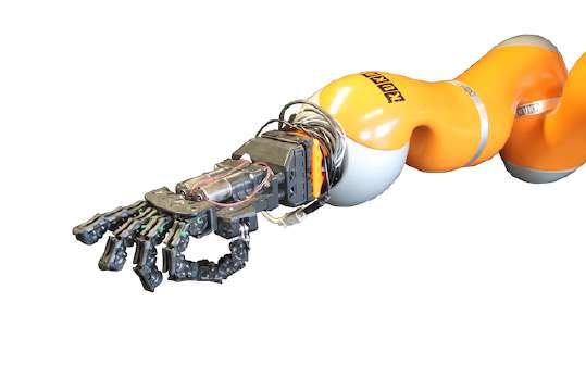
IEEE TRANSACTIONS ON ROBOTICS, VOL. XX, NO. Y, JANUARY 2018 2
was recognized to be not ideal for describing the extremely
adaptive nature of human hands in grasping and manipulating
objects. In the soft synergy model [17] the issue is addressed
by considering postural synergies as only prescribing motion
of a virtual reference hand toward which the physical hand is
dynamically attracted. The actual hand posture emerges as an
equilibrium between environment resistance to penetration and
hand compliance. In [18] some of the authors of the present
paper showed that a system of differential transmissions and
compliant elements can be designed so as to implement a
combination of any number of soft synergies. The idea of
designing force distribution mechanisms that replicate the soft
synergy model was called adaptive synergies. Its application
brought to the development of Pisa/IIT SoftHand [19] (see
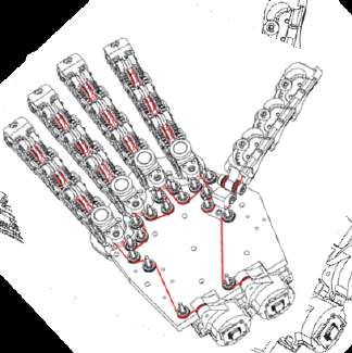
figure 3(a)), an anthropomorphic robotic hand implementing Figure 2. Schematic of a robotic hand with adaptive synergies grasping
one soft synergy. Even with such a small actuation space, the an object. The prime movers, on the left (in green) generate motion
hand was able to realize a vast range of grasps, thanks to its acting on the angles σ . Those motions are mapped to the hand joint
physical adaptiveness and compliance. angles q through the matrix R, which collects the transmission ratios.
The final posture of the hand depends on the external wrenches fext =
[ f1T , f2T , ...]T , the internal torques τa = [τ1 , τ2 , ...]T and the springs
However, while very effective in many practical conditions, elasticity (matrix E collects all the stiffness in its elements ei, j ).
Pisa/IIT SoftHand presents obvious limitations in terms of
dexterity if compared to its natural counterpart. So, facing
the need of augmenting the dexterity of these kind of simple II. BACKGROUND
hands, the following problem arises: how to increase the
The simplest definition of postural synergies is an ordered
hand functionalities without sensibly increasing mechanical
basis of the vector space of joint variables q ∈ Rn , resulting
complexity?
from Principal Component Analysis of the covariance matrix
obtained from experimental measurements of human subjects
This paper deals with this complexity-dexterity trade off by
during normal hand use [25]. The eigenvectors of the covari-
proposing a novel framework for the design of tendon driven
ance matrix ordered by their eigenvalues form the columns of
underactuated hands, which in continuity with our previous
the synergy matrix S, so that it holds
work, we will refer to as augmented adaptive synergies. The
main idea behind this approach is to exploit friction effects to q = Sσ , (1)
generate extra motions with minimal changes in the original
mechanics. Using this approach we present the design and val- where σ ∈ Rns represents the posture in the synergy basis
idation of a novel self-contained robotic hand, named Pisa/IIT S ∈ Rn×ns . While the complete description of the joint space
SoftHand 2 (called hereinafter SoftHand 2). This novel hand would require ns = n, experimental evidences suggest that
is able to perform both precision and power grasps (Fig. 1), as a reduced basis is sufficient to explain a large part of the
well as to manipulate objects while maintaining a stable grasp covariance of grasp postures during common grasping tasks
through autonomous finger motions dictated by its mechanical [25]. These experiments however were conducted while sub-
intelligence. Note that to implement in-hand manipulation in jects mimed grasp, without physically interacting with objects,
fully actuated hands, sophisticated algorithms [20], [21], [22] as hand deformations due to contact forces would confound
and sensing strategies [23] are generally required. In contrast, results. As a consequence, the synergy model in (1) is adequate
SoftHand 2 can manipulate objects of different shapes with to describe pre-shaping phases of grasp, but fails to predict
just two degrees of actuation, and requires only a very simple how grasping forces are actually generated in contact.
control strategy. To address this issue, [17] proposed to use the synergy
model to generate reference motions for the hand. It also
The paper is organized as follows. After recalling the introduced a model of compliance of the hand to account for
main elements of the adaptive synergy framework in Sec. II, forces arising from resistance to inter-penetration of bodies.
we introduce and discuss the augmented adaptive synergies This soft synergy model postulates that under such attraction
framework in Sec. III for a generic tendon-driven mechanism. and repulsion forces, the hand reaches the equilibrium config-
Sec. IV presents SoftHand 2 mechanical design. In Sec. V uration described by
we derive a dynamical model of the proposed hand, to per- q = Sσ −CJ T fext , (2)
form simulations motivating the considered control policy and
corroborating the analytical results. SoftHand 2 performance where C represents the grasp compliance and the term J T fext
are tested through several experiments in Sec. VI. The present collects all contact forces acting on the hand (see Fig. 2).
paper extends [24], where the proposed actuation principle was Due to technological difficulties, the realization of an ar-
preliminarily introduced and implemented in an exploratory tificial hand implementing the model (2) was not obtained
prototype. directly. Instead, [18] introduced the design technique of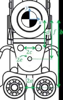
IEEE TRANSACTIONS ON ROBOTICS, VOL. XX, NO. Y, JANUARY 2018                                                                               3

                                                                              III. AUGMENTED ADAPTIVE SYNERGIES
                                                                        A. From Friction Effects to Actuation Augmentation
                                                                           The ideal model presented in section II does not account for
                                                                        dissipative effects that are encountered in any real mechanism.
                                                                           Fig. 4(a) shows a sketch of a robotic finger, driven by a
                                                                        unique tendon, with significant quantities marked. In a tendon
                                                                        driven differential mechanism, one of the main source of
                                                                        nonlinearity is the friction generated by pulleys guiding the
                                                                        tendon throughout the hand transmission system.
                                                                           To mathematically describe the effects of friction we con-
        (a) Original Pisa/IIT SoftHand.    (b) THE Second Hand.         sider the m + 1 tendon segments, delimited by the m pulleys.
                                                                        We assume inextensible tendons, and thus constant speed and
Figure 3. Robotic hands designed through adaptive synergies: Pisa/IIT
SoftHand integrates one DoA in a compact setup, while THE Second Hand   tension within each segment. Let T j and v j be the tension and
implements four synergies at the cost of a cumbersome structure.        speed of the j −th segment, and v ∈ Rm+1 and T ∈ Rm+1 be the
                                                                        two vectors collecting these terms. We refer to the j −th pulley
                                                                        radius as r j . To write compact expressions in the following
adaptive synergies, which exploits differential mechanisms and          we also define ri, j as the radius r j of the j − th pulley, if the
the space of self-motions to adapt to the external world. For           pulley is part of joint i, i.e. if a change in qi is reflected in a
a hand which is actuated by means of t tendons connected                change of the length of the j − th segment. The value of ri, j
to as many motors through a differential mechanism with                 is zero otherwise. Fig. 4(b) shows the j − th portion of the
transmission distribution matrix R, one can write a relation            transmission mechanism, composed by two successive tendon
between the tendon positions x ∈ Rt and joint variables as              segments, and the pulley which separates them. By balancing
                               Rq = x ,                           (3)   velocities at j − th pulley we obtain m equations in m + 1
                                                                        unknowns, in the form
and, by kineto-static duality, infer                                                                                    n
                                                                                                    dl j (q)
                             τ = RT τM ,                          (4)               v j = v j−1 +            = v j−1 + ∑ r j,i q̇i ,    (8)
                                                                                                      dt               i=1
where τ is the joint torque vector and τM is the tendon tension         where v j is the velocity of the j − th segment, and l j (q) its
vector. The equilibrium of the joint torques is obtained by             length. Note that the length of the segment changes only if it
including a linear elastic force in joint space (−Eq), and the          passes through a joint. In that case a variation of joint angle
contribution of external forces (J T fext )                             is reflected in a proportional variation of the segment length.
                        J T fext = RT τM − Eq .                   (5)      We complete the velocity balance through a boundary
                                                                        equation defined as
Finally, combining (3) and (5) and solving yields
                                                                                                          v0 + vm
       q =(−E −1 + E −1 RT (RE −1 RT )−1 RE −1 )J T fext +                                       ṡ = −           .                     (9)
                                                                  (6)                                        2
                 −1 T       −1 T −1
            +E      R (RE      R ) x,                                   Where v0 and vm are the velocities of first and last segments
which can be made equivalent to the soft synergies Eq. (2)              of the tendon, and ṡ is the residual sliding speed. Note that the
by identifying the tendon position with the synergy reference           variable s is an extra degree of freedom independent from the
variable (i.e. x = σ ), and by properly designing the parameters        joint angles q, which describes the relative motion of the two
in R and E so that                                                      ends of the tendon. Consider indeed that when all the degrees
                                                                        of freedom of the hand are constrained (i.e. q̇ ≡ 0), the tendon
        S = E −1 RT (RE −1 RT )−1 = R+
                                     E
                                                                  (7)   can still slide along its path, being all pulleys idle.
       C = E −1 − E −1 RT (RE −1 RT )−1 RE −1 = PR⊥ E −1 .                 Analogous considerations can be done for the balance of
This method was used for the design of the Pisa/IIT SoftHand            tensions at the j − th pulley
(Fig. 3(a)), where the differential mechanism is obtained using
a single motor (i.e. t = 1) which actuates all joints at the same                             T j = T j−1 −V j (v j ) ,                (10)
time through a tendon. The physical parameters were chosen              where T j is the tension on the j −th segment. The tension loss
such as to implement the first soft synergy of grasp [25]. With         V j (v j ) is due to friction on the j −th pulley. We complete the
the same method it is possible to add more synergies to the             tension balances through the m + 1-th equation
hand by adding other tendons in parallel to the first one. As
a proof of concept of multi-synergy hands, a prototype was                                          τM = T0 + Tm ,                     (11)
presented in [18] (see Fig. 3(b)). However, multi-synergies
hands require multiple tendons to be independently routed               which accounts for the total pulling force τM applied by the
through all hand joints, hence a large number of pulleys and            motor on the synergy σ . T0 and Tm are the tensions of first
an overall increase in size, weight, and complexity.                    and last portions of the tendon.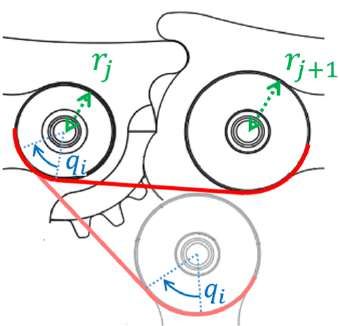
IEEE TRANSACTIONS ON ROBOTICS, VOL. XX, NO. Y, JANUARY 2018 4
where we defined the transmission maps
(
RT = −R̄T ev
(16)
D(q̇, ṡ) = −R̄T (−M −1V (M −1 R̄q̇ − 2 ev ṡ)) .
Eq. (15) clearly introduces the possibility of using tendon
sliding ṡ as an actuation, with the non-linear input field D(q̇, ṡ).
This is in addition to the input τM mapped as in Eq. (4), de
facto doubling the amount of DoA realized by each tendon.
To simplify the transmission model D(q̇, ṡ), it is instru-
mental to define a specific model for the friction force V (v).
Consider initially a dynamic Coulomb-like friction model (as
e.g. described in [26])
(a) Finger
V (v) = Vmax tanh(v) = Vmax tanh(M −1 R̄q̇ − ev ṡ) , (17)
where tanh(·) is intended component-wise for vectors. In
section V-A we discuss different friction models. Assuming
the system in equilibrium (i.e. q̇ ≡ 0), and considering ev =
[1, 1 · · · 1]T , (16) yields
D(ṡ) = −R̄T (M −1Vmax tanh(2ev ṡ))
(18)
= −R̄T M −1Vmax ev tanh(2ṡ).
Introducing Eqs. (15) and (18) in the force balance (5), we
(b) Pulley obtain
Figure 4. Panel (a) presents the scheme of an adaptive finger actuated through J T fext = RT u1 + RTf u2 − Eq , (19)
a tendon, with main variables highlighted. Panel (b) shows a portion of the
mechanism. It is composed by two tendon segments, and the pulley that where u1 = τM , u2 = tanh(2ṡ), and
separates them. qi is the i −th joint angle, v j and T j are the speed and tension, (
respectively, of each segment of the tendon along its routing, r j,i is the radius RT = −R̄T ev
r j of the j − th pulley when it is on joint i, or 0 otherwise. (20)
RTf = −R̄T M −1Vmax ev .
In analogy to section II, we define a synergy-like input σf
Finally we impose the map between tensions and joint (
torques, i.e. Rq = σ
(21)
m+1 Rf q = σf .
τi = − ∑ r j,i Tj , (12)
j=1 Rewriting Eqs. (19) and (21) in matrix form we obtain
T T
T
where r j,i is defined as in Eq. (8), and τi is the torque applied −E [R Rf ] q J fext
R u1 = σ , (22)
by the tendon on the i − th joint. 0/
We rewrite the previous equations in matrix form as Rf u2 σf
where the left term matrix is always non singular. Through
MT +V (v) + eτM = 0
block inversion the solution of (22) can be written as
Mv − R̄q̇ = −2eṡ (13) +
R σ ⊥ −1 T
τ = −R̄T T, q= + PR,R f E J f ext , (23)
Rf E σf
where M ∈ Rm+1×m+1 , R̄ ∈ Rn×m+1 and e = [0, 0, ..., 0, 1]T ∈ which explicitly specifies the relationship between synergistic
Rm+1 . Note that the element ( j, i) of R̄ is r j,i . Note also that inputs and hand configurations, supporting our proposed idea
V (v) is a vector function, with j − th element V j (v j ). to exploit friction to enhance the controllability of the hand.
From (13) we explicit the velocity and tension distributions
v and T as B. Effect of routing changes
(
v = +M −1 R̄q̇ − 2 ev ṡ We consider here the possibility of changing the routing of
(14) the tendon, i.e. the order by which the tendon passes through
T = −M −1V (v) − M −1 eτM = −M −1V (v) + ev τM ,
pulleys, as an additional design parameter to shape the hand
where ev = −M −1 e = [1, 1, . . . 1, 1]T . Combining (14) with the closure. Fig. 5 shows an example of two hands with the same
third equation in (13), the overall relation between ṡ, τM , and structure but different routing.
joint torque vector τ yields To describe the routing we introduce the permutation matrix
P ∈ Rm+1×m+1 . Its rows identify the hand pulleys, and the
τ = −R̄T (−M −1V (M −1 R̄q̇ − ev ṡ) + ev τM ) columns identify the tendon portions. Pi, j = 1 if the j-th portion
(15)
= RT τM + D(q̇, ṡ) . of the tendon is driven by the i-th pulley, Pi, j = 0 otherwise.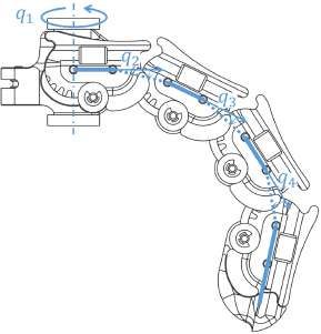
IEEE TRANSACTIONS ON ROBOTICS, VOL. XX, NO. Y, JANUARY 2018 5
All the derivations of the previous section can be generalized
by substituting v and T with their reorganized counterparts Pv
and PT respectively. Thus the overall effect is to modify Eq.
(13), into
M P T +V (P v) + eτM = 0
M P v − R̄q̇ = −2eṡ (24)
T
τ = −R̄ PT .
The two directions of actuation R, Rf become
(
RT = −R̄T ev
(25)
RTf = −R̄T PM −1 PT Vmax ev .
It is worth noticing that the effect of a different routing reflects
just in a change of the second direction of actuation Rf , leaving
R unchanged.
(a) Routing 1 (b) Routing 2
C. Design Remarks Figure 5. A simple adaptive hand with main quantities highlighted. qi is the
i −th joint angle. v0 , v17 and T0 , T17 are the speed and the tension at the two
The method of Adaptive Synergies [19] was motivated by ends of the tendon. ri is the radius of the i − th pulley. We consider here two
the idea of using Eq. (7) for designing parameters R, E such possible routings, i.e. orders in which the tendon passes through pulleys.
that a desired synergy basis S could be obtained. Here, we
extended this method including the possibility of designing
where 0/ is a zero matrix and 0̄ is a zero vector of opportune
also the friction parameters in Vmax and the tendon routing
dimensions. The block R̄i refers to the i-th finger, and it
P. To clarify the Augmented Adaptive Synergies approach,
contains the radii of the pulleys acting on that finger joints.
consider the simple example of Fig. 5; a hand with three
The friction effects matrix Vmax has the diagonal form
fingers. This hand has a total of 6 joints and 17 pulleys. They
0 ... 0 0
V
divide the tendon into 18 segments, each with constant velocity 1
0 V2 ... 0 0
and tension. T , v, q are tensions, velocities and joint angles
Vmax = ... .. .. .. ..
∈ R18×18 , (30)
vectors respectively . . . .
0 0 0 V17 0
T1 v1 q1 0 0 0 0 0
T = ... , v = ... , q = ... . (26)
where Vi is the friction coefficient associated with the i-th
T18 v18 q6 pulley. Note that the last row of R̄, Vmax and M reflect Eq.
We start by considering the routing in panel (a), which (9) and Eq. (11). From Eq. (20), we obtain the vectors R, Rf
corresponds to a P equal to the identity. So to describe hand representing the two directions of actuation
structure we specify in the following the matrices in (13). r1 + r5
Independently from the hand structure, M presents the form r2 + r4
−1 1 0 . . . 0 0 T
r6 + r10
R = , (31)
0 −1 1 ... 0 0 r7 + r9
.. .. .. .. .. .. r13 + r17
M= ∈ R18×18 . (27)
. . . . . .
r14 + r16
0 0 0 ... −1 1
1 0 0 ... 0 1 4 17
r1 − r5 r1 + r5
∑ Vi + ∑ Vi
The two matrices incorporating hand structure are R̄ and Vmax .
2 i=1 2 i=5
The transmission between tendon and joints is described by r2 − r4 3 17
r2 + r4
the matrix
∑ Vi + ( ∑ Vi −V1 )
2 i=2 2 i=4
R̄1 0/ 0/
r6 − r10 9 r6 + r10 17 5
0/ R̄2 0/
∈ R18×6 , + ( ∑ Vi − ∑ Vi )
R̄ =
0/ 0/ R̄3
(28)
2 ∑ Vi 2
i=6 i=10 i=1
RTf =
. (32)
0̄ 0̄ 0̄ r −r 8
7 9 r7 + r9 17 6
∑ Vi + ( ∑ Vi − ∑ Vi )
2 2
with i=7 i=9 i=1
0 0
r − r 16 r13 + r17 12
13 17 + (V17 − ∑ Vi )
r1 0
r6
0
0 0 2 ∑ Vi 2
i=13 i=1
0 r2 0 r7 r13 0
r14 − r16 15 r14 + r16 17 13
R̄1 = R̄2 = R̄3 = ∑ Vi + ( ∑ Vi − ∑ Vi )
0 0 0 0 0 , (29)
r14 2 i=14 2 i=16 i=1
0 r4 0 r9 0 0
From (31) clearly results that R can be designed through the
r5 0 r10 0 0 r16
r17 0 choice of pulley radii semi-sum. Additionally, (32) shows that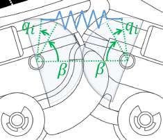
IEEE TRANSACTIONS ON ROBOTICS, VOL. XX, NO. Y, JANUARY 2018 6
Rf can be shaped independently from R through pulley radii
semi-differences and friction coefficients. We consider here
equal pulley radii, friction and elastic effects, i.e. ri = r̄, Vi = V̄
∀i, and E = k I. From Eq. (23), the free-closure configuration
space is
1 17
1 17
1 2
Span , . (33)
1 2
1 −19
−19
1
The first direction is a coordinate closure of all angles, while
the second one corresponds roughly to a closure of the first
finger and an opening of the third, or vice versa.
As an example of independent design of closure directions,
we change the friction on pulley 11 (i.e. V11 = α V̄ ) and the Figure 6. The Pisa/IIT SoftHand 2 evolves Pisa/IIT SoftHand through the
semi-difference of pulley radii acting on the joint q3 (i.e. r6 = introduction of an additional DOA, powered by a friction based transmission
system. The hand design is self-contained, including the whole actuation
r̄ +β and r10 = r̄ −β ). The resulting free-closure configuration system, sensors, power and control electronics.
space is
1 16 1 −1
1 16 1 −1
transmission system. Pisa/IIT SoftHand 2 has 19 joints. Five
1 1 1 β 5
Span 1 , 1 + α 1 + −1 ,
(34) of them are simple revolute joints, and they implement the
r adduction/abduction movement of each finger. The remaining
1 −17 −2 −1
1 −17 −2 −1
14 joints are compliant rolling-contact element joints [27] (see
appendix A for more details). This choice strongly increases
where α ∈ (0, +∞), β ∈ (−r̄, +r̄). Hence we can use friction
the hand robustness, such as the similarity between its kine-
to modulate differences in closure between one finger and the
matics and the one of the human hand. Elasticity is introduced
others, and radii variations to modulate joint closure on a same
in each joint as discussed in appendix B. A single tendon
finger.
moves from the palm base, through all the fingers. Two motors
To clarify the effect of a routing change, we consider the actuate the tendon, pulling it from its two sides. If the motors
routing in Fig. 5(b). The corresponding matrix P is move in the same direction, the tendon length is shortened,
0/ Π5 × 5 0/ and the SoftHand 2 closes. This corresponds to a σ command
P = Π5 × 5 0/ 0/ , (35) in Eq. (23). If instead the two motors move in opposition the
0/ 0/ I8 × 8 tendon slides (i.e. ṡ 6= 0), and the hand moves according to
the friction-driven DoA. This corresponds to a σf command
where each block represents a finger, I8 × 8 ∈ R8 × 8 is the in Eq. (23). Fig. 1 graphically represents these two degrees of
identity matrix and Π5 × 5 ∈ R5 × 5 is the matrix with all actuation.
zero elements except to the ones on the anti-diagonal (i.e.
These two free closures are designed through the proposed
Πi,6−i = 1 ∀ i ∈ {1 . . . 5}, and 0 otherwise).
Augmented Adaptive Synergies framework. Their choice is
Hence, from Eq. (25), tacking equal pulleys and elastic
motivated by a trade-off between human inspiration and sim-
effects (i.e. ri = r̄, Vi = V̄ ∀i, E = k I), the following free closure
plicity of implementation. For the closure related to the first
configuration space results
degree of actuation σ we target a coordinate closure of all
1 2 fingers analogous to the first synergy of grasp in humans
1 2
[25]. This seems to be a very fundamental ingredient of
1 17
Span , . (36) human hand control, since the same synergy was discovered
1 17
during analysis of haptic exploration [28] and environmental
1 −19
−19 constraint exploitation [29]. For the second DoA, we target
1
a behavior similar to the one extensively described in the
Thus the net effect of this routing change is to leave the first
toy example of Sec. III-C. Indeed, the relative opening and
direction unchanged, and to modify the second, reorganizing
closing of left fingers w.r.t. right ones (and vice versa) is found
its elements.
in the second and third postural synergies of grasp [25][30],
in the second manipulation synergy in [31], in the second
IV. AN AUGMENTED SYNERGY DRIVEN HAND: synergy of haptic exploration [28], and in the third synergy of
THE PISA/IIT SOFTHAND 2 environmental constrain exploitation in [29]. So the intuition
We present here the Pisa/IIT SoftHand 2, an anthropo- that we follow here is that the implementation of a similar
morphic robotic hand evolving the Pisa/IIT SoftHand by motion could be a key ingredient for embedding an higher
the introduction of a friction mediated DoA. Fig. 6 shows level of dexterous capabilities. This was tested in extensive
the hand prototype, while Fig. 7(a) shows a sketch of the experiments, presented in Sec. VI.
IEEE TRANSACTIONS ON ROBOTICS, VOL. XX, NO. Y, JANUARY 2018                                                                                                     7

                        (a) Routing                                              (b) Exploded sketch                              (c) Motor and encoder

Figure 7. Sketches of SoftHand 2 prototype. The red line in panel (a) highlights the tendon route. Panel (b) presents main components of SoftHand 2: (1)
are the two motors, (2) are the four encoders, (3) is the control and power electronics. Panel (c) reports a 2D section of the motor and encoder assembly.

                                        (a)                                                                             (b)

Figure 8. Pisa/IIT SoftHand 2 presents a completely self contained design, i.e. motors, sensors and electronics are all on-board. This enables an easy integration
in robotic manipulators. As an example panel (a) shows SoftHand 2 mounted on Kuka LWR. Panel (b) shows instead the application of SoftHand 2 as a
prosthesis. The hand is here integrated with a custom socket designed for sEMG prosthetics.

   We designed custom pulleys with equal radii 3.5mm.                             from Austrian Microsystem. Two encoders are included for
All are made of the same material, with a friction constant                       each motor, as depicted in Fig. 7(b). This choice is due to the
                                   N
approximately of v̄ ' 0.3 mm           [32]. We made the elastic                  necessity of having an absolute measurement of motor angles,
elements of Natural Rubber with the addition of Carbon                            robust to possible unexpected switching off of the electronics.
                                   N
Black, to obtain k ' 1.2 mm           . Neglecting the four long                  The number of tics of the two encoders is selected to be
fingers abduction joints (see Sec. V for more details) and                        coprime. The absolute angle is then derived integrating the two
considering a linear elastic field, the input directions of the                   measurements through the Chinese remainder theorem [33].
two DoAs results from Eq. (20) as the span of [1, . . . , 1]T N and                 The firmware is implemented on a custom electronic board,
[33, 33, 33, 17, 17, 17, 1, 1, 1, −15, −15, −15, −31, −31, −31]T N.               mounted on the bottom part of the hand. Its schematics are
As      prescribed        by    (23),    the   free-closure    con-               openly released, and they are available on-line as part of
figuration space is the span of [1, . . . , 1]T and                               the Natural Machine Motion Initiative [34]. The implemented
[2, 2, 2, 1, 1, , 1, 0, 0, 0, −1, −1, −1, −2, −2, −2]T ,                          control algorithm is discussed in Sec. VI-A.
compatibly with physical joint limits. Thus both closures are
                                                                                     We designed the geometry of hand bottom part, to guarantee
in line with the desired ones. We will test the ability of the
                                                                                  an easy connection with standard mechanical interfaces. It is
proposed design to present such behavior through accurate
                                                                                  worth noticing that thanks to the proposed actuation principle,
simulations in the next section, and experimentally in Sec.
                                                                                  combined with the discussed mechanical design, SoftHand 2
VI.
                                                                                  is completely self-contained. Motors, electronics, and sensors
   Fig.s 7(a) and 7(b) show two CAD views of SoftHand                             are all on-board, and only the energy supply is external to
2, with main components highlighted. The hand includes                            the hand. This compact design allows the easy plug-and-play
two MAXON DC-X 22s 24V motors, mounted on the back.                               integration of the SoftHand 2 with robotic manipulators. Fig.
We also included 86 : 1 gearboxes, characterized by 15W of                        8(a) shows the integration of Pisa/IIT SoftHand 2 with a Kuka
continuous output power. A single Dyneema tendon runs in                          LWR. This was made possible by the introduction of just two
the whole hand.                                                                   custom elements: a ROS node and a 3D printed flange (both
   The motor positions are acquired using magnetic sensors                        available at [34]).
IEEE TRANSACTIONS ON ROBOTICS, VOL. XX, NO. Y, JANUARY 2018 8
κj cj
Another application enabled by the hand self-contained where Σ and Λ collect r2j
and r2j
terms. θ ∈ R117 and z ∈ R117
design is the prosthetic one [35]. A preliminary example is are vectors collecting θ j and z j . Thus, by substituting the novel
shown in Fig. 8(b), where the SoftHand 2 is integrated with a friction balance in Eq. (16), the following friction driven input
socket. The mechanical interface is a standard Ottobock Quick field results
Disconnect Wrist. Two surface Electromyographic sensors
(sEMGs) are integrated in the socket. We used the on-board D(θ , z, q̇, ṡ) = RT M −1 (Λ (M −1 Rq̇ − ev ṡ) + Σ(θ − z)) , (40)
electronics to implement sEMG signal analysis and hand
control. Future work will be devoted to the further evolution where R has the same role of R̄ of Eq. (16), and it is derived
of the SoftHand 2 in the prosthetic direction, which is here in Appendix C. To complete the model, it remains to relate
R
θi
presented just as a proof-of-concept. to joint angles. This can be done by combining ri θi = vi dt,
Eq. (14), and by dividing for pulley radii
V. SOFTHAND 2 DYNAMIC MODEL AND
NUMERICAL SIMULATION θ = N(M −1 R q − ev s), (41)
To achieve a more complete understanding of Pisa/IIT Soft-
Hand 2 behavior, we develop in this section a numerical model, where N is the diagonal matrix having as i − th diagonal
including hand specific details. We describe in the following element r1i . Combining with (40), it yields to
the derivation of friction-related terms. The derivation of the
other terms is reported in the appendices. D(z, q, q̇, s, ṡ) = RT M −1 (Λ (M −1 Rq̇ − ev ṡ)
(42)
+Σ(N(M −1 Rq − ev s) − z))
A. Friction Terms
Thus, in presence of static friction (i.e. Σ 6= 0)
/ also a constant
In section III we modeled friction effects through a
sliding (i.e. s 6= 0 and ṡ ≡ 0) can serve as an actuation. It
Coulomb-like model [26]. The simplicity of the model was
is worth noticing that in accordance to the analytical model
instrumental for obtaining a closed form solution. However,
proposed in Sec. III, the input field RT M −1 Λ ev is equal to RTf
since the Pisa/IIT SoftHand 2 actuation system is based on
(Vmax and Λ have identical structure). Similar considerations
friction exploitation, we consider here a more accurate, yet
can be drawn for Σ N M −1 ev . However, the dependency on z
still computationally tractable, model of this effect. In this way
prevents from expressing the solution in closed form.
the analytical results can be tested in a realistic simulation
environment. Such model also clarifies the dependence of
the actuation from both the sliding s and its derivative ṡ, B. Overall resulting model
informing the control strategy, as it will be discussed in the
next subsection. Including dynamics effects, a generic robotic system driven
Considering the tension balance in Eq. (10), we model here by augmented adaptive synergies can be modeled as
the tension loss V (·) as the sum of viscous and static friction.
The viscous friction loss is a linear function of the tendon B(q)q̈ +W (q, q̇)q̇ + Γ(q) = Q(q)u + J(q)T fext , (43)
portion speed vi ci , where ci is the viscous friction coefficient.
For static friction we make use of the model proposed in where z dynamics is Eq. (37), q are hand joint angles, with
[36], which is able to combine good accuracy and limited their derivatives q̇, q̈. B(q) is the inertia matrix. W (q, q̇) col-
computational costs. The main idea is to introduce a virtual lects centrifugal, Coriolis and dissipative effects. Γ(q) collects
angle z j for each variable subjected to friction θ j . These elastic forces. J(q)T fext collects the
torque action
T on joints as
variables evolve according to the dynamic an effect of external forces. u , τM s ṡ collects inputs,
Q(q) is the transmission ratio from u to joint torques. In the
max if θ ≤ z − ∆max
θ j + ∆ j
j j j case of the Pisa/IIT SoftHand 2, these terms can be expressed
+ max
zj = θj −∆j if θ j ≥ z j + ∆max
j (37) as
zj otherwise,
W (q, q̇) , C(q, q̇) + F + RT M −1 Λ
where θ j is the angle describing the rotation of the j − th
Γ(q)
, G(q) − RhT M −1 Σ (N M −1 R q − z)
pulley, z j is the virtual angle at a certain time instant, and z+j T M −1 1
i
(44)
j Q(q) , R 2 M e v Σ N e v −Λ ev
is its value in the subsequent instant. ∆max is the friction range.
h iT
Friction force on the j − th pulley is (θ j − z j ) κ j , where κ j u
, τM s ṡ ,
takes into account the amount of friction. Note indeed that the
j
maximum static friction torque at the j − th pulley is ∆max κ j. where the derivation of B(q) and C(q, q̇) is described in
Combing these friction models with Eq. (10), the resulting Appendix A, the elastic field G(q) is described in Appendix
tension balance at the j − th portion is B, the transmission ratio R is described in Appendix C. We
cj κj consider friction on joint level as the linear function of the
T j = T j−1 − v j 2 − (θ j − z j ) 2 , (38)
rj rj joint derivatives F q̇, with F ∈ R19×19 diagonal. The remaining
terms are friction-related terms introduced in Sec. V-A. The
or, in matrix form,
MatLab code implementing the proposed model is available
MT + Λv + Σ(θ − z) + eτM = 0, (39) at the Natural Machine Motion Initiative website [34].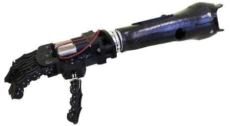
IEEE TRANSACTIONS ON ROBOTICS, VOL. XX, NO. Y, JANUARY 2018 9
0.8
0.8 0.6
0.6
0.5
0.6 0.4
0.4
0.4 0.3 0.2
0.2
0.2 0
0.1
Little 3
Little 3 -10 Little 2
Little 3 Little 2 Little 1
0 Little 2 Little 1 Ring 3
Little 1 0 Ring 3 Ring 2
Ring 3 Ring 2 -5 Ring 1
-10 Ring 2 -10
Ring 1 Ring 1 Middle 3
Middle 3 Middle 3 Middle 2
-5 Middle 2 -5 Middle 2 0 Middle 1
Middle 1 Middle 1 Index 3
0 Index 3 0 Index 3 Index 2
Index 2 Index 2 5 Index 1
5 Index 1 5 Index 1 Thumb 2
Thumb 2 Thumb 2 Thumb 1
Thumb 1 Thumb 1 10
10 10
(a) (b) (c)
6
6 6
4
4 4
2 2
2
5
0 5 0 0
0 5
0
20 0 20
40 50 0 40
60 60 80 -5
80 -5 -5 100
100 100 120
120
(d) (e) (f)
Figure 9. Effect of sliding in the steady state posture of SoftHand 2 (Panels (a,b,c)) and corresponding distributions of tension on the tendon (Panels (d,e,f)),
according to the proposed model. A constant force τM = 6N is applied in all the cases. In panel (a,d) a constant sliding speed ṡ is considered, which ranges
from − 5π mm 5π mm
2 s to 2 s . The final postures and tensions are polarized among two limit configurations, in accordance to Sec. III. Panels (b,e) present instead
the case of a constant sliding, i.e. s ranges from − 5π 5π
2 mm to 2 mm. In this case, postures and tensions change continuously from a limit posture to the other.
Panels (c,d) report a simulation analogous to the previous one, but where a constant force of 2 N is applied to the fingertip of the index finger. In panels (a,b,c)
abduction angles are omitted for the sake of clarity. Positive angles correspond to hand closure. In panels (d,e,f), the tensions corresponding to ṡ ∈{− 5π 2 ,
− 5π
4 , 0, 5π 5π mm
4 , 2 } s and s ∈{− 5π
2 , − 5π
4 , 0, 5π 5π
4 , 2 }mm are highlighted with black solid lines.
C. Identification a sliding with constant velocity ṡ can actuate the hand in
As already discussed in previous sections, we fixed pulley a novel direction of actuation. Fig. 9(a) shows the final
radii ri and spring stiffnesses ki by design. Geometric dimen- posture of SoftHand 2 when τM = 6N, and ṡ is constant with
sions are known too from the design, i.e. Ri β in Eq. (46), values ranging from − 5π mm 5π mm
2 s to 2 s . Fig. 9(d) presents the
a b c d in Eq. (50), phalanxes lengths in Appendix A. We corresponding tension distribution of the tendon. Results are
also make the simplifying assumption for friction coefficients in accord with indications of the theoretical model in Sec.
ci ,κi in Eq. (38), to be equal for each pulley. We estimate IV, i.e. the constant sliding generates a tension redistribution,
these values through an identification procedure. We also which produces a coordinated closure of ring and little, and
estimate abduction joint stiffnesses of Eq. (47). The dataset opening of the thumb and index fingers, when ṡ > 0, and vice
was collected through PhaseSpace system1 , an active led based versa when ṡ < 0.
motion capture system, with a sample time of 0.021sec and In Fig. 9(b) we report the results of an analogous simulation,
sub-millimeter precision. We placed a led on each phalanx where instead of constant ṡ, we consider a step variation of s
and five on the back of the palm. We close for 5 times by with values ranging from − 5π 5π
2 mm to 2 mm. Fig. 9(e) presents
applying a constant force (τM = 15N) and no sliding (s = 0). corresponding tension distribution on tendon. Interestingly
The data were filtered with a low pass filter with 2 poles the effect is similar to the constant sliding. However, these
in −20 Hz. The identification was performed by searching simulations demonstrate how, thanks to static friction, the
for the model parameters which generated in simulation a entire range of postures between the two extremes can be
closing behavior as close as possible to the one measured. achieved statically, using as control input s.
The considered distance measure was the 2−norm between To conclude the analysis, we present an example of how
the joint evolutions. an external force affects both hand posture (in Fig. 9(c)) and
tension distribution (in Fig. 9(f)). The input torque and sliding
is the same as in the latter simulation, but we introduced here a
D. Simulative Results 2N constant force applied orthogonally to index fingertip. The
Using the proposed identified model, we performed simu- most evident effect is, according to the introduced framework,
lations to test predictions of the analytical model of Sec. III. that index finger remains almost completely straight (angles
According to the Augmented Adaptive Synergy framework, equal to zero), while the other fingers close more. The most
affected finger is the thumb, which is near to the index and
1 http://www.phasespace.com/ with lower inertia w.r.t. the middle, which instead closes
IEEE TRANSACTIONS ON ROBOTICS, VOL. XX, NO. Y, JANUARY 2018                                                                                               10

Figure 10. Control architecture of Pisa/IIT SoftHand 2. Two Proportional-
Integral controllers regulate the angles of the two motors. No measurement        Figure 12. Sketch of the SoftHand 2 human-machine interface. It enables
from the hand posture is required. The references are expressed as σ and s.       an user to easily experiment with the robotic hand. The main subsystems are
                                                                                  highlighted in figure. The Interface includes a battery, the only component
                                                                                  not already included on-board on the hand.

                                                                                  for motor pulley radius r. The motor angles θ1 and θ2 are
                                                                                  mapped into σ and s according to the definition, i.e. as semi-
                                                                                  sum and semi-difference. The control action is defined by an
                                                                                                                                                N
                                                                                  error based PD control, with proportional gain equals to 0.2 rad
                                                                                            Ns
                                                                                  and 0.015 rad (heuristically tuned). The control is mapped back
                                                                                  to motor inputs as semi-sum and semi-difference.
        (a)                (b)                 (c)                (d)
                                                                                     Fig. 11 shows two photo sequences of SoftHand 2 move-
                                                                                  ments obtained through the considered controller. In the first
                                                                                  row s = 0, and σ moves from 0 to π2 . Thus hand closes
                                                                                  according to the first soft synergy, the same implemented in
                                                                                  the original Pisa/IIT SoftHand [19]. In the second row σ = π2
                                                                                  and s moves from 5π               5π
                                                                                                       2 mm to − 2 mm. This is the movement
                                                                                  that characterize SoftHand 2 w.r.t. the previous version, and
                                                                                  that is completely conveyed by friction effects. Note that the
                                                                                  behavior is coherent with the design framework (Sec. IV) and
       (e)                 (f)                (g)                  (h)            with the one obtained in simulation (Sec. V-D).

Figure 11. Photosequences of the two movements corresponding to the two
degrees of actuation. The first degree (a,b,c,d) resembles the first synergy of   B. Human-machine Interface
grasp. It generates a coordinate opening-closing of all the fingers, and it can
be used to establish firm grasps. The second degree (e,f,g,h) instead generates      The SoftHand 2 can be controlled through a digital input
a reconfiguration of the relative posture of the fingers, and it can be used to   by a computer. However, to realize a more natural control
execute more complex tasks. It resembles high order synergies of grasping         by a human operator, we designed a mechanical interface
and manipulation. This DoA is driven by friction, and controlled through a
sliding of the tendon.                                                            (see Fig. 12). The operator, holding the handle, can move a
                                                                                  joystick (512 ADAFRUIT analog 2-axis joystick) using the
                                                                                  thumb. Upward direction is translated into an increase of
slightly less. It is also interesting to note that the second DoA                 the σ command (i.e. first DOA), in an integral fashion. The
(i.e. the change of s) still generates a relative reconfiguration                 downward direction corresponds to a decrease of σ instead.
of the finger angles. Finally note that, as expected, the force                   Left and right directions correspond to a similar change of s.
increases the tension in the tendon portion nearest to the index,                 Pressing the select button reset the hand to initial position.
i.e. approximately from portion 1 to portion 50.                                  The handle also holds a battery pack in the lower part. Using
                                                                                  the proposed interface, we were able to test the SoftHand
              VI. EXPERIMENTAL VALIDATION                                         2 performances independently from automatic planning and
A. Control                                                                        control performances.
   From the simulations, it results that a step variation of
the sliding s is as much effective as a step variation of                         C. Experiments
sliding speed ṡ in generating limit configurations, and while                      The proposed actuation mechanism equips SoftHand 2 with
it appears more effective in generating intermediate ones. We                     various skills, that we present here in several experiments.
thus consider here a simple control law defining motor torques,                   Using only the first degree of actuation σ and relying on hand
such that desired s and σ are achieved. Fig. 10 shows the block                   adaptability, SoftHand 2 effectively performs different kinds
scheme. We map sliding s to the equivalent angle by divining                      of power grasps, as presented in Fig. 13. Note that different
IEEE TRANSACTIONS ON ROBOTICS, VOL. XX, NO. Y, JANUARY 2018 11
(a) (b) (c)
(a) Cube (b) Sphere (c) Tetris (d) Tetris
Figure 13. Using the first DoA, Pisa/IIT SoftHand 2 establishes stable power
grasps for all considered object shapes, with characteristics depending on the
affordances of the object.
(d) (e) (f)
(a) Banknote (b) Banknote (c) Card (d) Card
(g) (h) (i)
Figure 14. Comparison of grasping capabilities, between one DoA and two
DoAs. The grasps (a) and (c) are obtained using the first DoA of the SoftHand
2. The second DoA enables more natural grasps when grasping small and/or
flat objects, as with the banknote and the credit card in panels (b) and (d).
grasps are achieved even for the same object if grasped
(j) (k) (l)
differently, as shown in panels (c,d). In Fig. 14, SoftHand
2 grasps two thin objects using the first DoA in panels (a,c). Figure 15. Photosequences of tasks performed by SoftHand 2 mounted on a
The grasp is correctly established, but power grasp is not fully Kuka LWR. In (a,b,c) and (d,e,f) a same object is grasped from two different
sides, achieving two different grasps. In (g,h,i) the robot performs a precision
coherent with the task (e.g. the banknote is stretched). In panel grasp, and in (j,k,l) it slides a paper through the use of the index finger.
(b,d) the hand grasps the same objects using a combination of
the two DoAs. Natural precision grasps are achieved in this
case. As discussed above, the SoftHand 2 has a completely
self-contained design, enabling easy integration with robotic
manipulators. To show that, in Fig. 15 we mount Pisa/IIT
SoftHand 2 on a Kuka LWR, and we perform tasks exploiting
both DoAs. Panels (a,b,c,d,e,f) show two power grasps of a
same object. Panels (g,h,i) show a pinch grasp. In (j,k,l) the
robot performs a non-prehensile manipulation of a paper sheet
using the extended index finger. In Fig. 16, the ability of (a) (b) (c)
closing separately the two parts of the hand is exploited to
Figure 16. Two distant objects are sequentially grasped by closing separately
sequentially grasp two objects physically distant from each left and right sides of the hand.
other. In Fig. 17, the operator grasps a receiver using the first
DoA, and places it to the right side of the phone. Then he
uses the second DoA to obtain a posture as in Fig. 11(h).
Through the extended index he dials a phone number. Finally,
a power grasp is used to grasp again the receiver as to use
it. In Fig. 18 SoftHand 2 extracts a pen from its package
by exploiting all the range of postures that the second DoA
provides. It is worth noticing that these tasks are all intuitively
accomplished by specifying in feedforward a value of σ and s. (a) (b) (c)
It is the intelligence embodied in the mechanics that provides Figure 17. SoftHand 2 grasps a receiver using both DoAs, and places it on
the necessary mechanical adaptation to the environment and the right side of the phone. Then the index finger is extended, and used to
the objects to be grasped or manipulated. dial a number. Finally the receiver is grasped as to use it.IEEE TRANSACTIONS ON ROBOTICS, VOL. XX, NO. Y, JANUARY 2018 12
Figure 18. SoftHand 2 extracts a pen from its package, by relying on the pre-shaping ability provided by the second DoA.
In Fig. 19 we present SoftHand 2 in-hand manipulation A PPENDIX A: H AND K INEMATICS
skills. In all the examples, the object is grasped using the Each one of the four long fingers of Pisa/IIT SoftHand 2
first DoA, and then manipulated through a feedforward input presents three inter-phalangeal joints and one abduction joint,
of ramp shape on the second DoA. This is done independently as shown in Fig. 22. The abduction joint is a revolute joint,
from the object shape and size. The hand shapes autonomously while inter-phalangeal joints are compliant rolling-contact
its posture and maintains the grasp during manipulation, with- element (CORE) joints [27]. They are kinematically equivalent
out the need of additional reactive control. Moving to more to an RR arm, with a virtual (i.e. no inertia) intermediate
complex daily living activities, we exploit the manipulation link with an equality constraint between the two joint angles
skills introduced by the second degree of actuation and the (see Fig. 23(a) and 23(b)). Hence the 4-joint robotic finger
hand mechanical intelligence, in opening a jar in Fig. 20, and dynamics is equivalent to a 7R arm with standard kinematics,
pouring some coffee from a cup in Fig. 21. Note that both plus three equality constrains which reduce the DoFs to 4.
tasks are performed without any compensation at the wrist This model describes index, middle, ring and little fingers of
level. the Pisa/IIT SoftHand. The thumb differs slightly, since it has
We point the reader to the video footage, which includes one phalanx less and the abduction axis is oriented differently
all the presented experiments, and additional demonstration (see Fig. 7).
material.
A PPENDIX B: J OINT I MPEDANCE
VII. CONCLUSIONS Fig. 24 shows a schematic representation of inter-phalangeal
elastic mechanism. The spring characteristic is considered
In this paper the complexity-dexterity trade off related to linear. The spring deflection w.r.t. qi is 2Ri (cos (βi + qi ) −
the design of multi-synergistic compliant hands is faced by cos (βi )). Gear envelope radius Ri is considered constant. The
the introduction of a novel actuation principle, exploiting the angle of the spring connection with respect to the segment
friction inevitably encountered in tendon systems to turn it connecting the envelope centers is referred as βi . Resulting
to advantage. We formalized this idea in a novel framework, spring energy is
called augmented adaptive synergy framework. From the appli-
4
cation of this idea we derived the design of the Pisa/IIT Soft-
E(q) = ∑ 2ki R2i (cos (βi + qi ) − cos (βi ))2 . (45)
Hand 2, an anthropomorphic robotic hand, with two degrees of i=2
actuation, and 19 degrees of freedom. The physical parameters
of the hand are designed so that its free motions reproduce the The inter-phalangeal elastic field Gi (q) is
first synergy of grasp [25] and a reconfiguration of the fingers Gi (q) = 4 ki R2i (cos (βi ) − cos (βi + qi )) sin (βi + qi ). (46)
closely related to higher order synergies [31][28][29]. We also
presented an accurate mathematical model of the robotic hand, The abduction elastic mechanism is modeled as a torsional
to perform simulations which corroborate the analytical model, linear spring
and drive the controller design. We validated the prototype G1 (q) = k1 (q1 − q̄), (47)
in several realistic conditions, both with the hand connected
to a robotic manipulator and operated through a mechanical where q̄ is abduction joint rest position.
interface. Among the various abilities shown, the capacity of
performing in-hand manipulation of objects of different sizes A PPENDIX C: T RANSMISSION R ATIO
is of particular interest. Indeed this is here obtained without Fig. 25 presents the left side of the inter-phalangeal joint
the need of any feedback, and completely relying on the actuation system. The variation of tendon length due to the
intelligence embodied in the hand mechanical structure. Future closure of i-th joint li (q) is (r j + r j+1 )qi , where r j , r j+1 are
work will focus on the development of high level control radii of the pulleys acting on the i-th joint left side. Hence
and planning algorithms, which can take fully advantage from from kineto-static relationship, the torque on the i − th joint
the demonstrated hand capabilities. We will also investigated due to the left side of the mechanism is equal to (r j + r j+1 )T j .
the possibility of combining the here proposed Augmented Total torque is obtained adding up right and left sides
Adaptive Synergies, with Dynamic Synergies [37], to further
increase the hand capabilities. τi = (r j + r j+1 )T j + (rk + rk+1 )Tk , (48)IEEE TRANSACTIONS ON ROBOTICS, VOL. XX, NO. Y, JANUARY 2018 13 Figure 19. Examples of in-hand manipulation. A same feedforward input allows to rotate objects with different shapes, relying on the intelligence embodied in the mechanism. Figure 20. Example of in-hand manipulation. We can use SoftHand 2 for opening a jar without main compensations on the wrist level. Figure 21. Example of in-hand manipulation. Following a feedforward input, SoftHand 2 pours coffee from a cup to another.
IEEE TRANSACTIONS ON ROBOTICS, VOL. XX, NO. Y, JANUARY 2018                                                                                                     14

                 (a) side view                         (b) top view
                                                                                 Figure 25. Schematic representation of inter-phalangeal actuation system, in
Figure 22. A finger of Pisa/IIT SoftHand 2. It can be kinematically described    its rest and flexed positions. The red lines represent the tendon. Hand closure
as a 7R arm with three equality constrains, resulting in a 4-DoFs model.         is associated to a reduction of tendon length proportional to the radii of pulleys
                                                                                 actuating the joint.

          (a) Rest position                      (b) Flexed position

Figure 23. The inter-phalangeal joint is a realization of a CORE joint. We                         (a)                                      (b)
model it as an RR arm, with a virtual (i.e. no inertia) intermediate link. The
pure revolute constraint between the two phalanxes translates into an equality
constraint between the two angles of the arm.

where τi is the total torque acting on the joint, and rk , rk+1 are
the radii of the two pulleys acting on the i-th joint right side.
Note that other tendon configurations are possible, as shown in
Fig. 26, with transmission ratio: (a) r j + r j+1 , (b) r j − r j+1 , (c)                          (c)                                      (d)
−r j + r j+1 , (d) −r j − r j+1 . This introduces an addition degree
of freedom in the mechanical design that we do not further                       Figure 26. Tendon configurations in interphalangeal actuation system. The
                                                                                 red lines represent the tendon. Each configuration enables to implement a
discuss further for the sake of space.                                           different, even negative, transfer ratio.
   A different structure is used to actuate the abduction joint.
Fig. 27 shows the mechanism in various configurations, with
significant quantities highlighted. We refer to ll (q1 ) and lr (q1 )             is the abduction angle. Here we neglect variations of l1 (q1 )
as the lengths of the left and right portions of the tendon. q1                  and l2 (q1 ) associated with changes of the tendon tangency
                                                                                  point. Joint torques depend on left and right side tension
                                                                                 hTL , TR throughi two different transmission ratios, X(q1 ) ,
                                                                                    ∂ l1 (q1 ) ∂ l2 (q1 )
                                                                                       ∂ q1 , ∂ q1        . Thanks to the symmetry of the mechanism
                                                                                  w.r.t. q1 , we consider only configurations (a-b) in Fig. 27, i.e.
                                                                                  q1 ≥ 0. The results are extended for q1 < 0, substituting |q1 |
                                                                                  to q1 , and inverting the order of the two terms.
                                                                                     There is a range of values of q1 for which there is no contact
                                                                                  between the central pulley (i.e. the one of radius e in Fig.
                                                                                  27(d)) and the tendon. Outside the interval the transmission
                                                                                  geometry changes. Thus derivation of l1 (q1 ) and l2 (q1 ) has to
                                                                                  be done separately for both cases. Transmission ratio is
           (a) Rest position                    (b) Flexed position                                            (
                                                                                                                 X − (q1 ), if q1 ≤ qcontact
Figure 24. Schematic representation of the inter-phalangeal spring                                    X(q1 ) ,                                  (49)
system, in rest (a) and flexed (b) positions. qi is the joint angle, β is                                        X + (q1 ), if q1 > qcontact ,
the angle of the spring connection with respect to the horizontal, Ri
is the envelope radium.                                                          where X − , X + are transmission ratio in no contact and contact
                                                                                 case, and qcontact = min{q∗ ∈ [0, π2 ] s.t.: X − (q∗ ) = X + (q∗ )}.
IEEE TRANSACTIONS ON ROBOTICS, VOL. XX, NO. Y, JANUARY 2018 15
R EFERENCES
[1] A. Kochan, “Shadow delivers first hand,” Industrial robot: an interna-
tional journal, vol. 32, no. 1, pp. 15–16, 2005.
[2] M. Grebenstein, A. Albu-Schäffer, T. Bahls, M. Chalon, O. Eiberger,
W. Friedl, R. Gruber, S. Haddadin, U. Hagn, R. Haslinger, et al., “The
dlr hand arm system,” in Robotics and Automation (ICRA), 2011 IEEE
International Conference on, pp. 3175–3182, IEEE, 2011.
[3] Z. Xu and E. Todorov, “Design of a highly biomimetic anthropomorphic
robotic hand towards artificial limb regeneration,” in Robotics and
Automation (ICRA), 2016 IEEE International Conference on, pp. 3485–
3492, IEEE, 2016.
[4] M. Zaremsky, L. E. Weiss, and T. A. Mutschler, “Servo robot gripper,”
Apr. 1 1986. US Patent 4,579,380.
[5] S. Montambault and C. M. Gosselin, “Analysis of underactuated me-
chanical grippers,” Journal of Mechanical Design, vol. 123, no. 3,
pp. 367–374, 2001.
[6] A. M. Dollar and R. D. Howe, “The highly adaptive sdm hand: Design
and performance evaluation,” The international journal of robotics
research, vol. 29, no. 5, pp. 585–597, 2010.
(a) q1 > 0 (b) q1 = 0 [7] G. Smit, R. M. Bongers, C. K. Van der Sluis, and D. H. Plettenburg,
“Efficiency of voluntary opening hand and hook prosthetic devices, 24
years of development?,” JRRD: Journal of Rehabilitation Research &
Development, 49 (4), 2012, 2012.
[8] L. Birglen, C. M. Gosselin, and T. Laliberté, Underactuated robotic
hands, vol. 40. Springer Science & Business Media, 2008.
[9] L. Zollo, S. Roccella, E. Guglielmelli, M. C. Carrozza, and P. Dario,
“Biomechatronic design and control of an anthropomorphic artificial
hand for prosthetic and robotic applications,” IEEE/ASME Transactions
On Mechatronics, vol. 12, no. 4, pp. 418–429, 2007.
[10] T. Laliberté, M. Baril, F. Guay, and C. Gosselin, “Towards the design
of a prosthetic underactuated hand,” Mechanical Sciences, vol. 1, no. 1,
pp. 19–26, 2010.
[11] L. U. Odhner, L. P. Jentoft, M. R. Claffee, N. Corson, Y. Tenzer, R. R.
Ma, M. Buehler, R. Kohout, R. D. Howe, and A. M. Dollar, “A com-
pliant, underactuated hand for robust manipulation,” The International
Journal of Robotics Research, vol. 33, no. 5, pp. 736–752, 2014.
[12] R. Deimel and O. Brock, “A novel type of compliant and underactuated
robotic hand for dexterous grasping,” The International Journal of
Robotics Research, p. 0278364915592961, 2015.
[13] N. Feng, Q. Shi, H. Wang, J. Gong, C. Liu, and Z. Lu, “A soft robotic
hand: design, analysis, semg control, and experiment,” The International
(c) q1 < 0 (d) Significant quantities Journal of Advanced Manufacturing Technology, pp. 1–15, 2018.
[14] M. Santello, G. Baud-Bovy, and H. Jörntell, “Neural bases of hand
Figure 27. Actuation system of the abduction joint. In (a-c) we present the synergies,” Frontiers in computational neuroscience, vol. 7, 2013.
joint in different configurations, the red lines represent the tendon. In (d) we [15] M. Ciocarlie, C. Goldfeder, and P. Allen, “Dexterous grasping via eigen-
highlight significant quantities, needed to derive the tendon length. grasps: A low-dimensional approach to a high-complexity problem,”
in Robotics: Science and Systems Manipulation Workshop-Sensing and
Adapting to the Real World, Citeseer, 2007.
[16] C. Y. Brown and H. H. Asada, “Inter-finger coordination and postural
Simple geometrical considerations (see Fig. 27) bring to the synergies in robot hands via mechanical implementation of principal
components analysis,” in Intelligent Robots and Systems, 2007. IROS
following expressions for tendon lengths 2007. IEEE/RSJ International Conference on, pp. 2877–2882, IEEE,
2007.
−a −c [17] A. Bicchi, M. Gabiccini, and M. Santello, “Modelling natural and
l1 (q1 ) = || − Rq1 ||
−b −d artificial hands with synergies,” Philosophical Transactions of the Royal
Society B: Biological Sciences, vol. 366, no. 1581, pp. 3153–3161, 2011.
a c
l2− (q1 ) = || − Rq1 || (50) [18] G. Grioli, M. Catalano, E. Silvestro, S. Tono, and A. Bicchi, “Adaptive
−b −d synergies: an approach to the design of under-actuated robotic hands,”
in Intelligent Robots and Systems (IROS), 2012 IEEE/RSJ International
a e c−e
l2+ (q1 ) = || − Rq1 || + || ||. Conference on, pp. 1251–1256, IEEE, 2012.
−b −f f −d [19] M. G. Catalano, G. Grioli, E. Farnioli, A. Serio, C. Piazza, and A. Bicchi,
“Adaptive synergies for the design and control of the pisa/iit softhand,”
where || · || is the Euclidean norm, and Rq1 is the clockwise The International Journal of Robotics Research, vol. 33, no. 5, pp. 768–
rotation matrix of an angle q1 . We obtain X(q) from (49) by 782, 2014.
[20] Z. Li, P. Hsu, and S. Sastry, “Grasping and coordinated manipulation
deriving (50). X(q), together with (48), specifies completely by a multifingered robot hand,” The International Journal of Robotics
matrix R. Research, vol. 8, no. 4, pp. 33–50, 1989.
[21] V. Kumar, E. Todorov, and S. Levine, “Optimal control with learned
local models: Application to dexterous manipulation,” in Robotics and
ACKNOWLEDGMENT Automation (ICRA), 2016 IEEE International Conference on, pp. 378–
383, IEEE, 2016.
The authors want to thank Alberto Brando, Andrea Di [22] J. Shi, J. Z. Woodruff, P. B. Umbanhowar, and K. M. Lynch, “Dynamic
Basco, Michele Maimeri, Alessandro Raugi, and Gaspare in-hand sliding manipulation,” IEEE Transactions on Robotics, 2017.
[23] H. Yousef, M. Boukallel, and K. Althoefer, “Tactile sensing for dexter-
Santaera for their really valuable support in the development ous in-hand manipulation in roboticsa review,” Sensors and Actuators
and validation of the prototype. A: physical, vol. 167, no. 2, pp. 171–187, 2011.You can also read


