Dissimilar Welding and Joining of Cemented Carbides - MDPI
←
→
Page content transcription
If your browser does not render page correctly, please read the page content below
metals
Review
Dissimilar Welding and Joining of
Cemented Carbides
Binghui Ma 1 , Xiaonan Wang 1 , Chunhuan Chen 2 , Dongran Zhou 3,4 , Peiquan Xu 1,3, * and
Xiujuan Zhao 2, *
 1   School of Materials Engineering, Shanghai University of Engineering Science, Shanghai 201620, China;
     mabinghui0129@163.com (B.M.); 15738773508@163.com (X.W.)
 2   School of Materials Science and Engineering, Dalian Jiaotong University, Dalian 116028, China;
     cch051@hotmail.com
 3   Shanghai Collaborative Innovation Center of Laser Advanced Manufacturing Technology, Shanghai 201620,
     China; dongran98@163.com
 4   MAHLE Holding (China) Co., Ltd., Shanghai 201401, China
 *   Correspondence: pqxu@sues.edu.cn (P.X.); zhaoxj@djtu.edu.cn (X.Z.);
     Tel.: +86-21-6779-1204 (P.X.); +86-411-8410-6863 (X.Z.)

 Received: 26 September 2019; Accepted: 21 October 2019; Published: 28 October 2019

 Abstract: Cemented carbides have been widely used in aerospace, biomedical/wearable sensor,
 automobile, microelectronic, and other manufacturing industries owing to their superior physical and
 chemical properties at elevated temperatures. These superior properties, however, make it difficult to
 process these materials using conventional manufacturing methods. In this article, an overview of the
 welding and joining processes of cemented carbide and steel is given, followed by a few examples of
 welding processes. Cemented carbides can be successfully joined by sinter-bonding, brazing and
 soldering, laser beam welding, tungsten inert gas (TIG) welding, diffusion welding, friction welding,
 electron-beam welding, and chemical vapor deposition. An overview of the benefits and drawbacks
 of brazing and soldering of cemented carbide and steel is presented, including reports on joint design,
 processes, and selection of brazing filler metals. The laser welding of cemented carbide and steel is
 addressed and reviewed, including reports on gap bridging ability, the inclusion/absence of filler
 metals, interlayers, and laser/TIG hybrid welding. Finally, a section is devoted to explaining the main
 issues remaining in the welding and joining of cemented carbide, corresponding solutions, and future
 work required.

 Keywords: cemented carbides; dissimilar welding; sinter-bonding; brazing; laser welding; metal-inert
 gas welding; diffusion bonding; tungsten carbides

1. Introduction
     Cemented carbide was patented by Karl Schröter in 1923 [1] as a composite material of a “soft”
binder metal, usually cobalt (Co), nickel (Ni), iron (Fe), or a mixture thereof, and “hard” carbides such
as tungsten carbide (WC), molybdenum carbide (Mo2 C), tantalum carbide (TaC), chromium carbide
(Cr3 C2 ), vanadium carbide (VC), niobium carbide (NbC), titanium carbide (TiC), hafnium carbide
(HfC), or their mixtures [2–5].
     The metallographic microstructure of cemented carbides includes tungsten carbide (α-phase),
a binder phase (for example, based on Co, Ni, Fe) (β-phase), and a carbide with a cubic lattice (e.g.,
TiC, TaC), which may contain other carbides (e.g., WC) in solid solution (γ-phase) [6–8]. Murakami’s
reagent can be used as an etchant for the identification of α-phases through attack of the WC phases.
The etchant can reveal the microstructures and is a freshly prepared solution of equal quantities of

Metals 2019, 9, 1161; doi:10.3390/met9111161                                    www.mdpi.com/journal/metals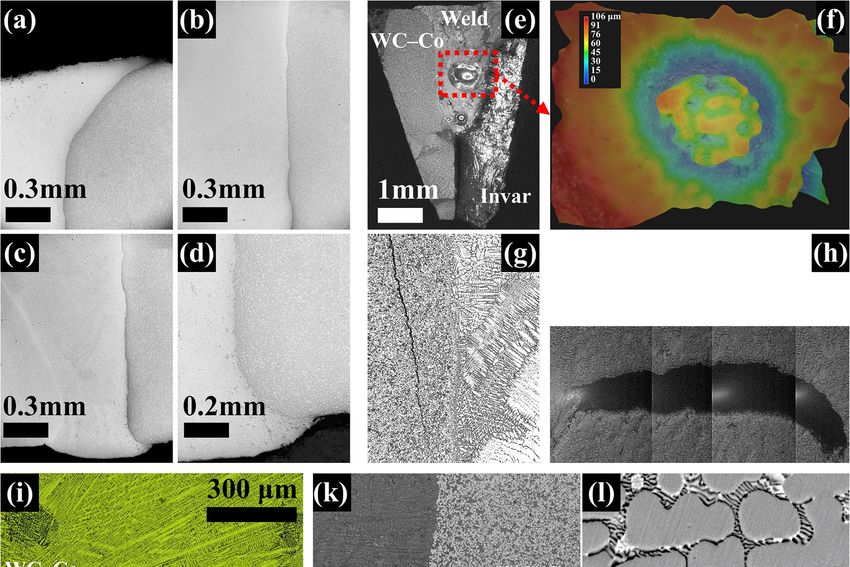
Metals 2019, 9, 1161                                                                                    2 of 21

10–20% (mass fraction) aqueous solutions of potassium hexacyanoferrate (III) [potassium ferricyanide]
and potassium or sodium hydroxide (10–20 g in 100 mL of water) [9]. The etching time is dependent
on the WC grain size. In general, the etching time is advised to be in the range of 5–6 min and increases
with the increasing grain size. To improve contrast, acid-based etchants, such as Nital (nitric acid and
ethanol), dilute hydrofluoric acid (HF), ferric chloride (FeCl3 ) solutions, or acidic mixtures such as
aqua regia (mixtures of nitric and hydrochloric acids) are used as additional etchants to attack the
binder phase.
     Cemented carbides are widely used for high-speed cutting, printed circuit board drilling, rolling,
and mining (die, rings, rolls, blades, slitters, totors, stators) as hard metal or hard metal–steel composites.
Moreover, the micro drills for printed circuit boards (PCBs), oil gas nozzle fuel pumps, and hydraulic
components in jet engines, as well as automotive components (fuel pumps, fuel injectors, compressors,
and valve trains), are fabricated from cemented carbides.

2. Weld Processes

2.1. Sinterbonding
     Sinterbonding is an important method used to join cemented carbides to other materials. Sintering
is the central process of powder metallurgy. Powders of most metals will sinter when heated to
approximately three-quarters of their absolute melting points while protected from oxidation or other
gaseous attack [10]. The metal flows viscously under the effect of surface tension and gas pressure [11].
Kuczynski et al. [12] suggests that the possible densification mechanism is (1) grain-boundary diffusion
or (2) volume diffusion with grain-boundary sinks. Generally, extensive grain-boundary sliding occurs
in most metals during deformation. In normal polycrystalline metals, such movements are very limited
because of blocking of neighboring grains. In a compact of compressed metal powder, Jones [13]
reported that neighboring grains were welded to each other at relatively few points and that, in the
early stages of sintering, considerable rearrangement of the relative disposition of the powder particles
under surface tension forces is possible by this mechanism [14]. Michalski and Rosiński [15] produced
sintered composites of diamond particles in a cemented carbide matrix prepared by pulse plasma
sintering (PPS) at high temperatures (Table 1). The transition layer consisted of a solid solution of
carbon and tungsten in cobalt. The diamond particles were observed to be strongly bonded with
the cemented carbide. Rodelas et al. [16] observed that sinterbonding WC–Co powder into a fully
dense nickel-iron tungsten heavy alloy (WHA) by hot pressing yielded a consolidated interface devoid
of porosity and voids. However, pressureless sintering is unsuitable because of debonding and
void formation resulting from differential sintering shrinkage. Co-rich η-carbides form preferentially
in regions of low carbon activity at the interface, which has been confirmed by a thermodynamic
evaluation of η-carbides as a function of carbon activity. The proposed WC–Co/WHA bonds can
be used to produce Friction Stir Welding (FSW) tools. Kitiwan et al. [17] fabricated WC and silicon
carbide-coated (SiC-coated) diamond composites by spark plasma sintering (SPS) at 1199–1600 ◦ C
for 300 s under 130 MPa under vacuum. The WC–diamond (SiC) composite exhibited high hardness
and fracture toughness. Michalski et al. [18] produced a WC–6Co/cBN composite at 1150 ◦ C under
a pressure of 100 MPa for 5 min using pulse plasma sintering (PPS). The melting cobalt film spread
over the surfaces of the WC and Cubic Boron Nitride (cBN) grains, and strong bonds formed between
them. The rapid heating rate was observed to lead to the generation of transient thermal compressive
stresses in the WC grains and subsequent grain refinement. The suitability of tungsten/steel joints
prepared by PPS has been demonstrated, and PPS is a promising method for fabricating components
of divertors [19,20]. The microwave sintering [21] time is too short to prevent grain coarsening and is a
useful technique to fabricate nano-sized cemented carbides. Partial transient liquid-phase bonding
(PTLP) [22] was also used to fabricate WC–Co/40Cr steel joints. Maizza et al. [23] reported a new
solid-state capacitor discharge sinter-welding (CDSW) process to obtain a WC–12Co/AISI M2 steel
joint. The advantages are that short processing times help to prevent the coarsening of steel or WC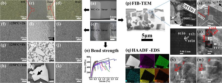
Metals 2019, 9, 1161                                                                                      3 of 21

grains and WC decomposition and minimize microstructural defects. These findings lay a foundation
for interface formation and surface science.

      Table 1. Dissimilar cemented carbide bonds prepared by sinter-bonding methods. PPS, pulse plasma
      sintering; SPS, spark plasma sintering; PTLP, partial transient liquid-phase bonding; CDSW, capacitor
      discharge sinter-welding.

                                                                                         Mechanical
                                                                           Temperature
  Hard Metals          Counterpart   Load (MPa)     Sintering Method                     Properties   Reference
                                                                              (◦ C)
                                                                                           (GPa)
    WC–Co            Diamond              -                PPS                 1000          23         [15]
    WC–6Co         W–3.5Ni–1.5Fe         30       Uniaxial Hot-Pressing        1325           -         [16]
      WC           Diamond (SiC)        130                SPS              1190–1600       30.5        [17]
    WC–6Co              cBN             100                PPS                 1150           -         [18]
      W            Eurofer97 steel        -                PPS                 1000           -         [19]
    W–La2O3             P91               -                PPS                  800           -         [20]
      WC                 Co               -        Microwave Sintering           -            -         [21]
    WC–10Co            40Cr             0.3               PTLP               950–1100         -         [22]
    WC–12Co           AISI M2             -              CDSW                    -            -         [23]
    WC–20Co            Invar              -       Liquid-phase sintering       1350           -         [24]

     As shown in Figure 1a, the sinter-bonding of Fe–36 wt.% Ni powder to WC–Co was performed
at 1300 ◦ C for 2, 8, and 16 h under vacuum [24]. The results indicate that the compacted Fe–36
wt.% Ni/WC–Co sinter-bonded powders yielded a consolidated interface comprised primarily of
hexagonal α-WC, cubic Fe0.64Ni0.36, and the presence of the Co3W3 complex (Figure 1b), whose
content increased as a function of holding time. Prolonged holding times promote bonding of the
WC–Co/Fe–Ni component. However, excessive holding times result in significant contractions and
failure by cracking. Normal grain growth (NGG) (Figure 1c) and abnormal grain growth (AGG)
(Figure 1d) occurred through the WC/Co/WC interfaces, not only in the liquid phase, but also in
the solid state, at lower temperatures. According to the results shown in Figure 1e,f, the abnormal
grains at the interface exhibited much larger grain sizes than the normal grains. AGG observed at the
WC–Co/Fe–Ni interface was characterized by a grain size of 6–9 µm. The maximal abnormal grains
were 6.5–8.5 times larger than the average grain size in the WC–Co base material in the vicinity of
the interface. The concentration gradient, together with a high stress imbalance at the WC–Co/Fe–Ni
interface, resulted in rotation, repacking, and rearrangement of the particles, which led to abnormal
grain formation (Figure 1g).
     The actual sintering temperatures are significantly lower than the melting points of cobalt or
tungsten carbide because of the formation of intergranular films (complexion) at the WC/Co interface
(Figure 1h). The nanosized powders are suggested to be the principal contributors to the initial rapid
grain growth because of the inherent large surface areas and short diffusion distances.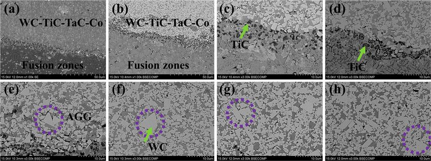
solid state, at lower temperatures. According to the results shown in Figure 1e,f, the abnormal grains
  at the interface exhibited much larger grain sizes than the normal grains. AGG observed at the WC–
  Co/Fe–Ni interface was characterized by a grain size of 6–9 µm. The maximal abnormal grains were
  6.5–8.5 times larger than the average grain size in the WC–Co base material in the vicinity of the
  interface. The concentration gradient, together with a high stress imbalance at the WC–Co/Fe–Ni
Metals 2019, 9, 1161                                                                                 4 of 21
  interface, resulted in rotation, repacking, and rearrangement of the particles, which led to abnormal
  grain formation (Figure 1g).

     Figure      Sinter-bonding
             1. 1.
        Figure     Sinter-bondingofofWC–Co
                                       WC–Cocemented
                                                 cemented carbide     and Invar
                                                             carbide and    Invaralloys.
                                                                                    alloys.(a)
                                                                                             (a)Schematic
                                                                                                 Schematic       illustration
                                                                                                              illustration  of of
     sinter-bonding
        sinter-bonding process. (b)(b)
                          process.  X-Rays
                                       X-RaysDiffraction   (XRD)
                                                 Diffraction       patterns
                                                               (XRD)          of sinter-bonded
                                                                       patterns   of sinter-bonded joints.  (c) Normal
                                                                                                        joints.            grain
                                                                                                                  (c) Normal
     growth.   (d) Abnormal
        grain growth.          grain growth.
                        (d) Abnormal            (e) Grain
                                       grain growth.    (e) size
                                                            Graindistribution  for specimens
                                                                   size distribution              far from
                                                                                       for specimens          interface
                                                                                                         far from         and (f)
                                                                                                                     interface
     at the
        andWC–Co/Fe–Ni       interface. (g,h)
             (f) at the WC–Co/Fe–Ni           Bright-field
                                         interface.           Transmission
                                                     (g–h) Bright-field       Electron Microscope
                                                                          Transmission                   (TEM) photographs
                                                                                           Electron Microscope         (TEM)
     using  FEI   Titan  Themis   200  TEM   microscope      (FEI,  Hillsboro,   OR,    USA)   and
        photographs using FEI Titan Themis 200 TEM microscope (FEI, Hillsboro, OR, USA) and high-    high-resolution        TEM
     photographs
        resolution TEM photographs showing the WC crystal lattices and the formation of intergranular films at
                     showing   the WC   crystal  lattices and   the formation    of intergranular     films   (complexion)
     the WC/Co interface. NGG, normal grain growth; AGG, abnormal grain growth. EDS, energy-dispersive
     X-ray spectroscopy. Adapted from [24], with permission from Elsevier, 2019.

2.2. Brazing

2.2.1. Background
     Brazing is one of the cheapest, most reliable, and efficient ways of making dissimilar joints, which
is one of the most important methods to join cemented carbide and steel. After fabricating a cemented
carbide, Schröter [25] patented the brazing method of producing a cemented carbide/steel joint.
The evolution of the cemented carbide joining method had the milestone significance in the history of
cemented carbides’ development. Table 2 summarizes the brazing processes and characteristic features
of the various types of brazing filler metals.

     Table 2. Chemical composition of filler metals and their brazing conditions and temperatures. OFHC,
     oxygen-free high conductivity; GTA, gas tungsten-arc.

                                                         Thickness      Body Material       Body         Temperature
        Composition             Brazing Conditions                                                                       Reference
                                                           (mm)              (1)          Material (2)      (◦ C)
   Cu-Borax/Mo/Cu-Borax/                   -                    -        Hard metal   Steel or iron          1100           [25]
  AuNi, Silver, AgCu, Copper          Vacuum                 0.127        WC–6Co          4340             810–1100         [26]
             WRe                     GTA braze                0.25         GE–15            -                   -           [27]
    CuAg, OFHC Copper             Sinter, hydrogen              -       WC–TiC/TaC–Co       -                1400           [28]
           CuMnCo                Induction, Argon           0.2/0.3         B30          40HM             1040–1120         [29]
            AgCuP                    Flame, flux                -           WC            steel            470–725          [30]
         AgCuZnCd                    Flame, flux                -         W–Co–Ti      AISI 4145            710–980         [31]
         AgCuZnCd                 Ultrasound, flux             0.2        WC–15Co        Be–Cu              640–750         [32]
       Zinc, AlSi-alloy         Ultrasound, fluxless            -           K10          T11302                 -           [33]
       AgZnCuNiMn                    GTA braze                  -         WC–10Co      AISI 1020              1300          [34]
            AgCu                      Vacuum                 0.8/2        WC–8Co        SAE1045            1100/850         [35]
         AgZnCuNi                     Vacuum                   0.3        WC–10Co     90MnCrV8                850           [36]
           CuZn(Ni)                        -                    -        WC-Co/Ni          410                  -           [37]
            CuZn                      Vacuum                   0.2        WC–8Co         3Cr13            1060–1100         [38]
           CuZnNi                     Vacuum                    -        WC–TiC–Co          -               940–960         [39]
             CuNi                     Vacuum                    -          WC–Co      Carbon steel              -           [40]
             CuNi                     Vacuum               0.1/0.04       WC–8Co          S45C               1050           [41]
           CuMnZn                     Vacuum                   0.2        WC–20Co        16Mn               940–980         [42]
     AgNi/CuZn/AgNi                Induction, flux            0.12        WC–15Co       35CrMo              710–770         [43]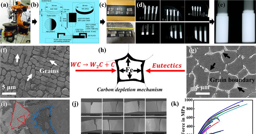
Metals 2019, 9, 1161 5 of 21
2.2.2. Joint Design
Joint design strongly affects the cooling rates of the weld metal and the heat-affected cemented
carbides. Joint design includes the section thickness, arrangement of the seams, geometry of the parts,
Metals 2019,
welded 9, x FOR
joint PEER REVIEW
geometry, and restraint of the welded joint. These variables determine the weldability 5 of 20
and the ease of fabrication of as-welded cemented carbides.
Figure
Figure 2a,b
2a,b present images of
present images of aa digging
digging machine
machine andand aa drag
drag pick.
pick. The
The cross-sectional
cross-sectional view
view along
along
section
section I–I at the top-right corner shows the brazed seam and joint geometry. The microstructures of
I–I at the top-right corner shows the brazed seam and joint geometry. The microstructures of
the
the cemented
cemented carbide
carbide base
base inin region
region “C”
“C” in
in Figure
Figure 2b
2b and
and the
the grain
grain size
size distribution
distribution are
are presented
presented in in
Figures 2c and
Figure 2c,d, d, respectively.
respectively. Compared Compared with as-welded
with as-welded cementedcemented
carbide with carbide
a highwith a high
cobalt cobalt
content, the
content,
magnified themicrostructures
magnified microstructures
in Figure 2e of in region
Figure“E”
2e of(Figure
region2b)
“E”reveal
(Figure 2b) reveal
a much a much
narrower narrower
intermediate
intermediate layer between the cemented carbide and fusion zone. Figure 2f shows
layer between the cemented carbide and fusion zone. Figure 2f shows the heterogeneous microstructures the heterogeneous
microstructures
in the fusion zone, in where
the fusion zone,carbide
tungsten where tungsten
exhibits acarbide
type ofexhibits
delicate amutual
type ofeffect
delicate
withmutual effect
multi-alloys.
with multi-alloys. The further magnified microstructures have cellular structures
The further magnified microstructures have cellular structures (Figure 2g). The electron back-scattered (Figure 2g). The
electron back-scattered diffraction (EBSD) (Hitachi S3400 N SEM with an HKL-EBSD,
diffraction (EBSD) (Hitachi S3400 N SEM with an HKL-EBSD, Tokyo, Japan) patterns in Figure 2h–j show Tokyo, Japan)
patterns in Figure 2h–j
the microstructures, show themaps,
orientation microstructures, orientation
and Smith factor. maps, and
The proposed Smith
joint factor.
design The proposed
(circular sandwich
joint design (circular sandwich structure: WC–Co/Cu–Ag/9SiCr) was concluded
structure: WC–Co/Cu–Ag/9SiCr) was concluded to be helpful for minimizing residual stresses. to be helpful for
minimizing residual stresses.
Figure 2.
Figure Joint design
2. Joint design and example of brazing of WC–Co cemented cemented carbide
carbide and and steel.
steel. (a) Digging
machine. (b) Drag pick. The joint geometry is shown in the top-right corner. (c)
machine. (b) Drag pick. The joint geometry is shown in the top-right corner. (c) Microstructures of Microstructures of
WC–Co
WC–Co cemented
cementedcarbide
carbide(region “C”“C”
(region in Figure 2b). (d)2b).
in Figure Coincidence site latticesite
(d) Coincidence (CSL) grain(CSL)
lattice boundaries.
grain
WC–Co/Cu–Ag/9SiCr joint (e) in region
boundaries. WC–Co/Cu–Ag/9SiCr joint“E”, (f)region
(e) in in region
“E”,“F”
(f) in
in Figure
region 2b,
“F”and (g) in the
in Figure 2b, fusion
and (g)zone in
in the
region “G” in Figure 2f. (h) Electron back-scattered diffraction (EBSD) pattern; the
fusion zone in region “G” in Figure 2f. (h) Electron back-scattered diffraction (EBSD) pattern; the top-top-right corner
showscorner
right the crystal
showspreferred
the crystalorientation. (i) EBSD orientation
preferred orientation. maps of heat-affected
(i) EBSD orientation WC–Co. WC–
maps of heat-affected Step
size: 150 nm. The colored areas are binders and tungsten carbides; different colors
Co. Step size: 150 nm. The colored areas are binders and tungsten carbides; different colors indicate indicate different
orientations
different (Euler angles)
orientations (Eulerand grains.
angles) (j)grains.
and Smith (j) factor.
Smith factor.
2.2.3. Processes
2.2.3. Processes
As shown in Table 2, tungsten and its alloys can be successfully brazed by vacuum brazing [26],
As shown in Table 2, tungsten and its alloys can be successfully brazed by vacuum brazing [26],
gas tungsten-arc (GTA) braze welding [27], sintered brazing in hydrogen [28], induction brazing with
gas tungsten-arc (GTA) braze welding [27], sintered brazing in hydrogen [28], induction brazing with
protective argon [29], flame brazing with flux [30,31], and ultrasound-assisted induction brazing with
flux [32] and without flux [33].
Thorsen et al. [28] discussed treatments to improve wettability while brazing cemented carbides
sintered in hydrogen furnaces with CuAg and oxygen-free high conductivity (OFHC) copper as filler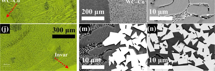
Metals 2019, 9, 1161                                                                                 6 of 21

protective argon [29], flame brazing with flux [30,31], and ultrasound-assisted induction brazing with
flux [32] and without flux [33].
      Thorsen et al. [28] discussed treatments to improve wettability while brazing cemented carbides
sintered in hydrogen furnaces with CuAg and oxygen-free high conductivity (OFHC) copper as filler
metals. The results revealed the wettability mechanism during brazing of cemented carbide. Pieczara
et al. [29] presented the brazing technology of B30 grade cemented carbide and 40HM steel with filler
metal Cu87Mn10Co3. The experimental joints were made with sandwich structures using distance
rods, steel mesh, and nickel mesh. The research provides guidance for the repeatability of the geometry
of the brazing process. Amelzadeh et al. [31] investigated the effect of the brazing filler metals on
WC–Co/steel joints. Additive nickel with a Na2B4O7 flux was observed to improve the strength of
the joints. Although the use of flux enables successful joining, it also generates voids within the joint,
which reduces the strength of the connection. Tillmann et al. [33] instead explored the feasibility of
brazing of cemented carbides to steel without a flux. The selected filler metals, Ag449, pure Zn, and an
AlSi-alloy, successfully wetted both materials and led to a dense connection.

2.2.4. Selection of Brazing Filler Metals
      Filler metals used for the brazing of cemented carbide included Zn-based, Ag-based [34–36], and
Cu-based [38–42] alloys, as well as “sandwich structure” alloys [43]. The main drawback of using
filler metals containing Silver (Ag) and Zinc (Zn) is the high potential of evaporation during soldering.
For this reason, in the most recently used filler materials, Zn is replaced by Stannum (Sn), Copper
(Cu), Nickel (Ni), Phosphorus (P), or Manganese (Mn), sometimes accompanied by small amounts of
Indium(In) or Sn, to decrease the melting temperature [30]. Cadmium (Cd) has been used to reduce
the brazing temperature and ensure a strong joint. Because of the restriction of using Cd, higher
temperatures are needed to produce sufficient joints with other filler metals; however, the process
became more complex by handling the residual stresses [36]. Cu reduces the stress levels because
of its higher ductility. Ni is an element that enters into complete solid solution with cobalt (Co) in
tungsten carbide. Chen et al. [37] fabricated a new functionally graded WC–Co/Ni component (FGWC)
with an Ni layer on the joining surface, which was designed to improve the wettability of solders on
the cemented carbide and relax the residual stresses [38]. This research lay the foundation for the
joining of cemented carbide and steels by introducing a functionally graded nickel wetted WC–Co/Ni
component. Lee et al. [40] patented a novel insert metal consisting of stacked (or double layered) Cu
alloy and amorphous Ni (MBF80) alloy. Increased amounts of Cr3 C2 were observed to be effective
in preventing the formation of the η phase (Co3 W3 C) and the coarsening of WC grains. Under the
same brazing conditions, the maximum shear strength was higher than that of a similar joint without
chromium carbide [41].
      Ag-based braze alloys result in excellent wettability of cemented carbide and steels, while the Co
is dissolved in the Ag-based filler metals [44]. Triantafyllou et al. [45] reported on a series of wetting
experiments on systems of pure Ag as well as Ag–Cu–Ti and Ag–Cu–Ni pseudo-alloys in contact
with widely used steels and ceramics to determine the interfacial properties of the above systems.
Pure Ag in air exhibited poor wettability with all the substrates with contact angles greater than 90◦ .
The Ag–Cu–Ti pseudo-alloy in vacuum exhibited improved wettability. The Ag–Cu–Ni pseudo-alloy in
air exhibited excellent wetting properties with contact angles of less than 10◦ . Ag-based braze alloys are
also used in dissimilar cermet brazing. Feng et al. [46] reported on a TiC cermet/Ag–31Cu–23Zn/steel
joint formed by vacuum brazing. Increasing the brazing temperature or time was observed to decrease
the amount of Ag-based solid solution in the middle of the braze alloy.
      Laansoo et al. [47] investigated the weldability of cermet (WC-15Co, TiC60/FeNi, TiC50/NiMo,
CrNi10, CrNi30) and steel (S45C, X10CrNi18-8) with 50–150 µm thick filler foils between the cermet–steel
parts prepared by induction brazing heated for 1 min under a pressure of 2–3 MPa. Northrop [48]
reviewed several braze alloys available for the brazing of cemented carbides to steel. The brazing
metals ranged from silver solders of low melting point to pure copper, with brazing temperatures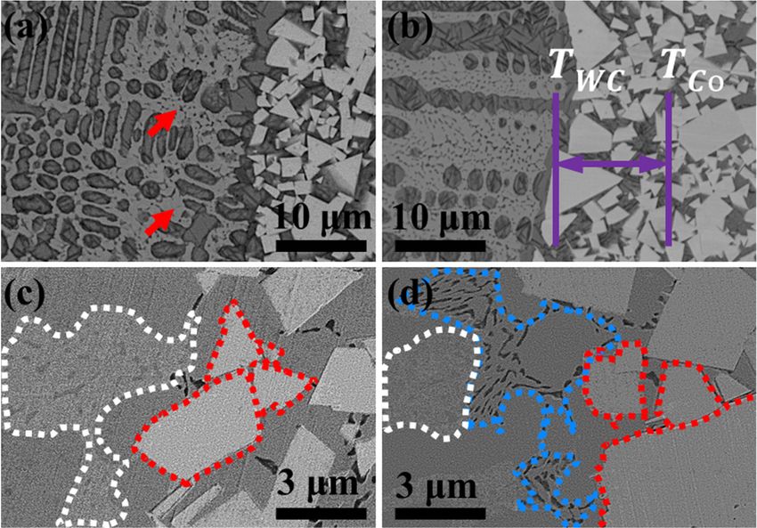
Metals 2019, 9, 1161                                                                                 7 of 21

from approximately 600 ◦ C to over 1050 ◦ C. The strength of the joints strongly depended on the braze
parameters [49].

2.2.5. Advantages and Application
     The main brazing techniques employed are torch brazing, induction brazing, and furnace
brazing [48]. To ensure slow and even heating and cooling, large structures should be furnace-brazed;
however, no technique can entirely eliminate the thermal stresses because of the differential contraction
that occurs as the assembly cools from the brazing temperature to ambient conditions. Smaller
components can be torch-brazed; however, most components are mass produced by induction brazing,
which is a clean, simple, and rapid method.
     Tungsten-based alloy and its welding lay a foundation for the application of dissimilar joints
of cemented carbide. Farrell et al. [50] and Lessman et al. [51] investigated the welding issues
and weldability of tungsten-based alloys. They showed that cracking is caused by the growth and
coalescence of small pores on the grain boundaries.

2.3. Laser Welding

2.3.1. Background
      Laser is an acronym for light amplification by stimulated emission of radiation (LASER). Alberta
Einstein established the theoretical foundations for the laser by optimizing Planck’s law of radiation
and the probability coefficients for the absorption, spontaneous emission, and stimulated emission of
electromagnetic radiation in 1917 [52]. A laser is made up of a laser medium (the material in which the
laser is generated), a pump source (provides the necessary activation energy to the laser medium), and
a laser resonator.
      The application of a laser on welding can decrease the distortion with lower heat input and high
efficiency and automation [53,54]. Laser welding is a competitive, high-efficiency process with high
user satisfaction and has been applied in a wide range of fields for steel, aluminum, titanium [55], and
magnesium alloys [56]. Laser welding is also a potential method to fabricate dissimilar WC–Co/steel
joints. The properties of laser-welded hard metals were considered to be sufficient for the fabrication
of values [57] or drag picks to be used in production in the rock mining industry or for oil and
gas applications.

2.3.2. Without Filler Metals
     Sandig et al. [58] reported on as-welded hard metals joints prepared by a laser and opened
the doors to further development of the use of lasers on hard metal. Tian et al. [59] fabricated a
dissimilar joint by wetting hard metal with molten steels and revealed the mechanism of dip soldering.
The plasma on the specimen surface increases the metallurgical bonding. Miranda et al. [60] reported
the application of the CO2 laser, neodymium/yttrium aluminum garnet (Nd/YAG), and fiber laser and
optimized the welding parameters. Nd/YAG (neodymium/yttrium aluminum garnet) was observed to
produce better as-welded joints. The research indicated that cobalt volatilization and overheating of
the cemented carbide were prevented by focusing the laser spot at the steel side.
     Figure 3 presents microstructures in a fusion boundary region in the joint prepared by laser
welding without filler metals. The research also indicated that laser is a potential technology for joining
cemented carbide and steel. The parameters, including heat input (laser power, scan speed), laser spot
position, defocusing amount, and local preheating by a “dry-run” of the laser scan, were observed to
affect the bead formation of a 2 mm thick plate. Within the range of parameter variations [61], for a
constant heat input, it appears that increasing the laser power has a greater effect on enhancing the
penetration and the bend strength than decreasing the laser scan speed.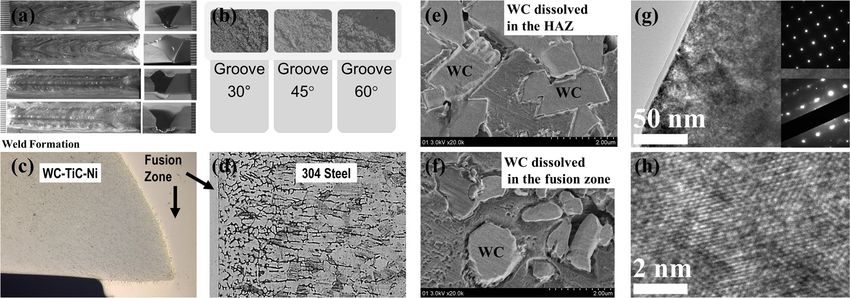
Metals 2019, 9, 1161                                                                                                8 of 21
Metals 2019, 9, x FOR PEER REVIEW                                                                                  8 of 20

             3. Laser welding of WC–Co cemented carbide and S45C carbon steel without filler metals. (a)
      Figure 3.
      Microstructures
      Microstructures in
                       in aa fusion
                             fusion boundary
                                     boundary region.
                                                 region. The
                                                          The red
                                                              red arrows
                                                                  arrows show
                                                                          show thethe mixed
                                                                                      mixed carbides.
                                                                                            carbides. (b) The higher
      temperature border
                   border (T   wc)) and lower temperature border (TCo
                             (Twc                                       Co)) of
                                                                             of the
                                                                                the fusion boundary region. (c), (d)
      Microstructures
      Microstructures and
                       and grain
                              grain growth
                                     growth in
                                             in aa fusion
                                                    fusion boundary
                                                           boundaryregion.
                                                                     region.

     At   a higher
      Another         magnification
                  study   on the laser in the literature,
                                       welding     of cementedthe microstructure
                                                                   carbide without(Figure     3a) consists
                                                                                      filler metals  by Costaof et
                                                                                                                 a al.
                                                                                                                   fusion
                                                                                                                       [63]
boundary      region   that  is several  WC     grains    wide  (≈  30  µm)   and  contained    more
indicated that the weldability increased with increasing cobalt content, because of its effect in      mixed    carbides.
The  higher and
improving      the lower    temperature
                     ductility              border of
                                and weldability.         the fusion boundary
                                                       Pre-heating,    post-heat region    are defined
                                                                                   treatment,            by the melting
                                                                                                 and nitridation      were
point  of tungsten
observed              carbidetoand
             to be helpful           the cobalt
                                  ensure   joint (Figure
                                                  integrity, 3b). The microstructure
                                                               increase   the strength,inandthe minimize
                                                                                                Figure 3c,dthe
                                                                                                             consists
                                                                                                                 residualof
half-dissolved     WC    (enclosed   by red   dotted    lines), iron-rich   face-centered   cubic
stresses [64]. Tungsten was observed to diffuse to the bead, inducing multiple W carbide formation (FCC)   (enclosed     by
white
in the dotted    lines),
        martensite       face-centered
                      structure          cubic (FCC)
                                  and contributing      tocobalt-rich
                                                            higher bead solid  solution, mixed carbide, and eutectic
                                                                           hardness.
microstructure
      Figure 4a–d   (enclosed
                        presentby a blue
                                    seconddotted    lines).(SE)
                                              electron        Brittle fracture during
                                                                  micrograph             bending occurred
                                                                                 and back-scattered           along
                                                                                                         electron       the
                                                                                                                     (BSE)
fusion  boundary     and   heat-affected  zone   (HAZ)     on the  cemented   carbide  side,
micrographs of laser-welded super-fine cemented carbide (WC–TiC–TaC–Co) and stainless steel  where   dissolution   of  WC
and  penetration
without             of Fe from
           filler metals.        the fusion
                           Although    blackzone    are believed
                                               titanium     carbidetograins
                                                                       have caused   embrittlement
                                                                             were observed     at the at the WC–matrix
                                                                                                      interface,  normal
interfaces.    Martensite    was  formed    in  the  fusion   zones
grain growth and abnormal grain growth were observed (Figure 4e–h).   and  exhibited   different  morphologies      in the
center of the fusion zone, near the cemented carbide, and on the steel side; the morphologies were
affected by the carbon [61,62].
     Another study on the laser welding of cemented carbide without filler metals by Costa et al. [63]
indicated that the weldability increased with increasing cobalt content, because of its effect in improving
the ductility and weldability. Pre-heating, post-heat treatment, and nitridation were observed to be
helpful to ensure joint integrity, increase the strength, and minimize the residual stresses [64]. Tungsten
was observed to diffuse to the bead, inducing multiple W carbide formation in the martensite structure
and contributing to higher bead hardness.
     Figure 4a–d present a second electron (SE) micrograph and back-scattered electron (BSE)
micrographs of laser-welded super-fine cemented carbide (WC–TiC–TaC–Co) and stainless steel
without filler metals. Although black titanium carbide grains were observed at the interface, normal
grain growth and abnormal grain growth were observed (Figure 4e–h).

      Figure 4. Laser welding of super-fine cemented carbide (WC–TiC–TaC–Co) and stainless steel
      without filler metals. (a) Second electron (SE) micrograph and back-scattered electron (BSE)
      micrographs (b–c) at low magnification and (d) high magnification showing the WC–TiC–TaC–
      Co/316L stainless steel interface. (e–h) Normal grain growth and abnormal grain growth (AGG) of
      WC grains near the interface.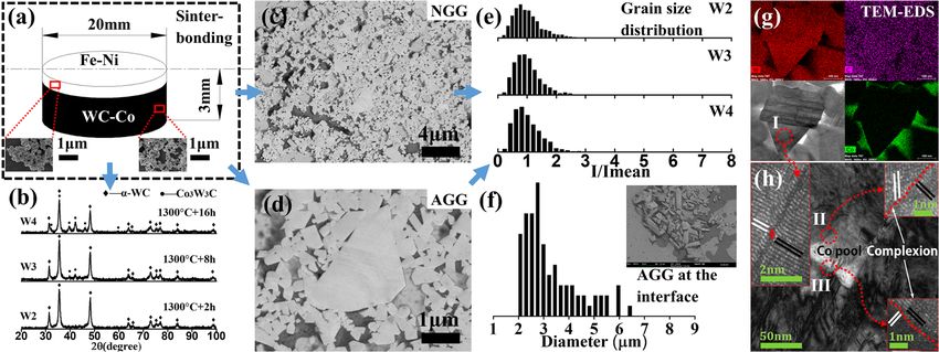
observed to be helpful to ensure joint integrity, increase the strength, and minimize the residual
stresses [64]. Tungsten was observed to diffuse to the bead, inducing multiple W carbide formation
in the martensite structure and contributing to higher bead hardness.
Figure 4a–d present a second electron (SE) micrograph and back-scattered electron (BSE)
micrographs of laser-welded super-fine cemented carbide (WC–TiC–TaC–Co) and stainless steel
Metals 2019, 9, 1161 9 of 21
without filler metals. Although black titanium carbide grains were observed at the interface, normal
grain growth and abnormal grain growth were observed (Figure 4e–h).
Figure 4. Laser welding of super-fine cemented carbide (WC–TiC–TaC–Co) and stainless steel without
Figure 4. Laser welding of super-fine cemented carbide (WC–TiC–TaC–Co) and stainless steel
filler metals. (a) Second electron (SE) micrograph and back-scattered electron (BSE) micrographs
without filler metals. (a) Second electron (SE) micrograph and back-scattered electron (BSE)
(b,c) at low magnification and (d) high magnification showing the WC–TiC–TaC–Co/316L stainless
micrographs (b–c) at low magnification and (d) high magnification showing the WC–TiC–TaC–
steel interface. (e–h) Normal grain growth and abnormal grain growth (AGG) of WC grains near
Co/316L stainless steel interface. (e–h) Normal grain growth and abnormal grain growth (AGG) of
the interface.
WC grains near the interface.
2.3.3. Buffered with Interlayers
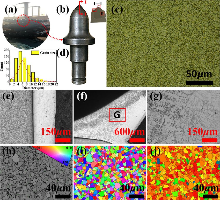
Guillaume first discovered the Invar effect in 1897 [65]. The Invar alloy has a low thermal
expansion coefficient over a wide temperature range [66,67]. Yu et al. [68] and Yao et al. [69] utilized an
Invar insert as a filler metal to join WC–Co cemented carbide and carbon steel prepared by fiber laser
welding. Figure 5 shows the laser welding of cemented carbide and steel with Invar as the interlayer.
Figure 5a shows the robotic welding systems used in the present search. The architecture of the
preparation of the WC–20Co/Invar/AISI 1045 welded joint consisted of the following: the dimensions
of the base metal were φ 58 × 3 mm, and the Invar interlayer was 0.5 mm thick. After welding,
the as-welded WC–Co/Invar/AISI 1045 specimens were evaluated using X-ray nondestructive testing
(Figure 5c). X-ray film maps (Figure 5d) were analyzed using image processing methods (Figure 5e).
The as-welded microstructures of the Invar fusion zones contained FCC primary dendrites γ
(nickel dissolved in γ-Fe), eutectic colonies, and mixed carbides. Figure 5f,g show the cellular grains
(white arrows) and grain boundaries (black arrows) between them, respectively. The Invar dendrites
may have further transformed from the bcc crystal structure to bcc → fcc constituents upon cooling [18].
Iron atoms play a key role in the formation of dendrites and eutectics. Driven by the carbon depletion
mechanism (Figure 5h), with decreasing welding speed and increasing heat input, it is evident that the
mixed carbides exhibited coarser eutectics and a higher value closer to the fusion boundary on the
WC–Co side.
Figure 5i shows the interfacial microstructures near the WC–Co/Invar interface. The areas
surrounded by red, blue, and white dotted lines indicate dissolving WC grains, the eutectic
microstructure, and the iron-rich solid solution, respectively. Figure 5j shows the effect on the
bend strength for different levels of welding speed. The fracture propagation paths for the face
bend-tested specimens are shown in Figure 5k. The 3 mm thick as-welded WC–Co/Invar/AISI
1045 specimens with lower heat input exhibited higher bend strength. Some specimens exhibited
transgranular cracking at the WC facet (Figure 5l,m). Cracks were observed to initiate from the HAZ,
propagate to the WC–20Co base metal, and finally fail in the HAZ near the cemented carbide. The
fracture of the other specimens was initiated from the fusion zone. In addition, the fractures occurred
in the fusion zone and propagated to the HAZ near the WC–Co cemented carbide. Dissolved and
half-dissolved WC was observed at the fracture surface (Figure 5n), with the red arrows indicating
the dissolved WC grains; cracks were also observed along the grain boundaries (Figure 5o). The
proportional limit [70] was also concerned.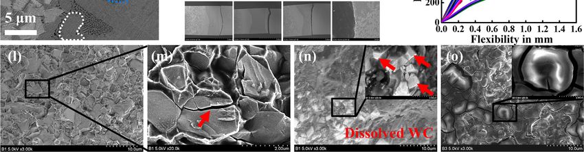
laser welding. Figure 5 shows the laser welding of cemented carbide and steel with Invar as the
 interlayer. Figure 5a shows the robotic welding systems used in the present search. The architecture
 of the preparation of the WC–20Co/Invar/AISI 1045 welded joint consisted of the following: the
 dimensions of the base metal were ϕ 58 × 3 mm, and the Invar interlayer was 0.5 mm thick. After
 welding, the as-welded WC–Co/Invar/AISI 1045 specimens were evaluated using X-ray
Metals 2019, 9, 1161                                                                          10 of 21
 nondestructive testing (Figure 5c). X-ray film maps (Figure 5d) were analyzed using image
 processing methods (Figure 5e).

      Figure5.5. Laser
     Figure       Laserwelding
                         weldingofofWC–Co
                                     WC–Cocemented
                                             cementedcarbide
                                                         carbideand
                                                                  andAISI
                                                                       AISI1045
                                                                            1045steels.
                                                                                  steels.(a)
                                                                                           (a)Robotic
                                                                                               Roboticwelding
                                                                                                       welding
     systems   for welding  of cemented  carbide and   carbon  steel. (b) Architecture  of  the preparation
      systems for welding of cemented carbide and carbon steel. (b) Architecture of the preparation of WC–  of
     WC–20Co/Invar/AISI 1045 welded joint: dimensions of φ 58 × 3 mm base metal, interlayer: 0.5 mm
      20Co/Invar/AISI 1045 welded joint: dimensions of ϕ 58 × 3 mm base metal, interlayer: 0.5 mm thick
     thick Invar. (c) X-ray nondestructive testing (NDT) of as-welded specimens. (d) X-ray detection film
      Invar. (c) X-ray nondestructive testing (NDT) of as-welded specimens. (d) X-ray detection film maps.
     maps. (e) Image processing showing the weld defect. (f,g) Grains and grain boundaries in the fusion
      (e) Image processing showing the weld defect. (f–g) Grains and grain boundaries in the fusion zone.
     zone. (h) Carbon depletion mechanism during welding. (i) Microstructures showing the grain growth
      (h) Carbon depletion mechanism during welding. (i) Microstructures showing the grain growth and
     and mixed carbide near the WC–Co/Invar interface. (j) Bend strength. (k) Face bend-tested specimens
      mixed carbide near the WC–Co/Invar interface. (j) Bend strength. (k) Face bend-tested specimens
     showing the fracture propagation path. (l–o) Bend fracture surface showing the interdendritic fracture
      showing the fracture propagation path. (l–o) Bend fracture surface showing the interdendritic fracture
     in the fusion zone and transgranular fracture in the heat-affected zone (HAZ). Adapted from [68], with
      in the fusion zone and transgranular fracture in the heat-affected zone (HAZ). Adapted from [68],
     permission from Elsevier, 2016.
      with permission from Elsevier, 2016.
     As shown in Figure 6a, the as-welded fusion zone exhibited larger plastic deformation than the
      The as-welded microstructures of the Invar fusion zones contained FCC primary dendrites γ
Invar base, which led to an increase in local strain fields and contributed to the dislocations (the white
 (nickel dissolved in γ-Fe), eutectic colonies, and mixed carbides. Figures 5f and 5g show the cellular
rectangle showing the deformation). Slip deformation indicated by the white line in Figure 6b–d
 grains (white arrows) and grain boundaries (black arrows) between them, respectively. The Invar
was considered to be a contributing deformation mechanism for the as-welded Invar Fe–Ni alloys.
Bright-field TEM image and high-resolution images show the dislocations and crystal lattice. Crystal
plane (111) is the priority.
[70] was also concerned.
As shown in Figure 6a, the as-welded fusion zone exhibited larger plastic deformation than the
Invar base, which led to an increase in local strain fields and contributed to the dislocations (the white
rectangle showing the deformation). Slip deformation indicated by the white line in Figure 6b–d was
Metals 2019, 9, 1161 11 of 21
Figure 6.
Figure 6. A
A typical
typical (a)
(a)TEM
TEMimage
image and
and (b)
(b)high-resolution
high-resolution TEM
TEM image
image ofof the
the as-welded
as-welded Fe–Ni
Fe–Ni samples
samples
with aaFourier
with Fourier transformation
transformation of white
of the the white rectangle
rectangle at the top-right
at the top-right corner showscorner shows
the slip the slip
deformation,
deformation,
and the inverse and the inverse Fourier-filtered
Fourier-filtered imagethe
image from inside from inside
white the white
rectangle rectangle
(c) in (a), and(c)
(d)inin(a),
(b)and (d)
shows
in (b)deformation,
slip shows slip deformation, Stacking
Stacking Faults (SFs) Faults
(white(SFs) (white
lines), lines), and dislocations
and dislocations (white T).from
(white T). Adapted Adapted
[69],
from permission
with [69], with permission from2017.
from Elsevier, Elsevier, 2017.
Mirski et al. [71] investigated and reviewed the application of laser welding on hard metals and
provided
provided aabasis
basisforfor
subsequent
subsequentresearch. The The
research. research showed
research the possibilities
showed of laser of
the possibilities joints between
laser joints
hard metals
between andmetals
hard carbonand steelcarbon
with Cu–Ag–Ni
steel withinterlayers
Cu–Ag–Niprepared using
interlayers a Triumpf
prepared discalaser.
using The laser
Triumpf disc
beam
laser. focusing
The laseron
beamthe steel surface
focusing onwas
the observed to bewas
steel surface helpful for avoiding
observed direct interaction
to be helpful for avoiding between
direct
the laser beam
interaction and hard
between the metal. Yin etand
laser beam al. [72]
hardreported
metal. on
Yinthe
et effect of the
al. [72] interlayer
reported thickness
on the effect on
of the
metallurgical bonding, microstructure, and bend strength. Figure 7a–d present cross-sectional views of
the microstructure of the as-welded specimens, base metal, joints, and HAZ. Figure 7e shows a typical
as-annealed specimen, and Figures 7f–h and 7i–k show the microstructures of the base metal and HAZ
annealed at 1250 ◦ C for 2 h, 8 h, and 16 h. The aggregates and grain growth were observed on the
cemented carbide side (Figure 7l–n). Increasing the thickness of the Invar interlayer from 1 to 1.5 mm
resulted in continuous metallurgical bonding, free of voids and oxide films. When the thickness was
increased to 2 mm, the porosity in the fusion zone increased and cracks developed near the fusion
boundary on the WC–Co side, reducing the strength. As shown in Figure 7o, the maximum bend
strength was achieved for 4 mm thick specimens with 1.5 mm thick Invar as the interlayer. The fusion
boundary, HAZ, and the fusion zone on the WC–Co side were susceptible to cracking.
The Focused Ion Beam (FIB) technique was used to prepare TEM samples (Figure 7p), and
the chemical compositions were measured using High angle Annular Dark Field (HAADF) energy
dispersive X-ray spectroscopy (EDS) (Figure 7q) [73]. The microstructures at the WC/M interface after
heat treatment were characterized using high-resolution TEM, revealing high densities of dislocations
(Figure 7r–w). Energy-dispersive X-ray spectroscopy (EDS) analysis suggested that long-range solute
diffusion occurred inside the WC grains and at the WC/Fe (Ni)/WC interfaces. These findings are
helpful for theoretical research on dissimilar cemented carbides and steels.The Focused Ion Beam (FIB) technique was used to prepare TEM samples (Figure 7p), and the
chemical compositions were measured using High angle Annular Dark Field (HAADF) energy
dispersive X-ray spectroscopy (EDS) (Figure 7q) [73]. The microstructures at the WC/M interface after
heat treatment were characterized using high-resolution TEM, revealing high densities of
dislocations (Figure 7r–w). Energy-dispersive X-ray spectroscopy (EDS) analysis suggested that long-
Metals 2019, 9, 1161 12 of 21
range solute diffusion occurred inside the WC grains and at the WC/Fe (Ni)/WC interfaces. These
findings are helpful for theoretical research on dissimilar cemented carbides and steels.
Figure7.7.Fiber
Figure Fiberlaser
laserwelding
weldingofofcemented
cementedcarbide
carbideand
andsteel
steelusing
usingInvar
Invarfiller
fillermetals.
metals.(a)(a)As-welded
As-welded
joint
joint(cross-sectional
(cross-sectionalview)
view)composed
composedofofWC–Co WC–Co(left
(leftside),
side),316L
316Lstainless
stainlesssteel
steel(right
(rightside),
side),and
andanan
Invar
Invarinterlayer
interlayer(middle).
(middle).Higher-magnification
Higher-magnification images
images of (b) base
of (b) material,
base (c) joint,
material, andand
(c) joint, (d) HAZ; (e)
(d) HAZ;
as-annealed joints
(e) as-annealed of WC–Co
joints of WC–Co(left(left
side) andand
side) 316316
L stainless
L stainless steel (right
steel side)
(right side)with
withananInvar
Invarinterlayer
interlayer
(middle) held at 1250 ◦ C; base materials held at 1250 ◦ C for (f) 2 h, (g) 8 h, and (h) 16 h; and HAZ held at
(middle) held at 1250 °C; base materials held at 1250 °C for (f) 2 h, (g) 8 h, and (h) 16 h; and HAZ held
1250 ◦ C for (i) 2 h, (j) 8 h, and (k) 16 h; and (l–n) carbide grain growth after annealing. (o) Bend strength.
at 1250 °C for (i) 2 h, (j) 8 h, and (k) 16 h; and (l–n) carbide grain growth after annealing. (o) Bend
(p) FIB–TEM
strength. (p)image,
FIB–TEM(q) HAADF–EDS images, and (r–w)
image, (q) HAADF–EDS images,bright–field
and (r–w) TEM and high-resolution
bright–field TEM and TEM high-
images showing structure and crystal lattice. Adapted from [72,73], with permission
resolution TEM images showing structure and crystal lattice. Adapted from [72,73], with permission from Elsevier, 2018.
from Elsevier, 2018.
2.3.4. Laser–TIG
InLaser–TIG
2.3.4. laser–TIG (tungsten-inert gas) hybrid welding, a laser beam interacts in the same molten pool as
the molten pool created by a secondary heat source. The first attempts to join a laser and conventional
In laser–TIG (tungsten-inert gas) hybrid welding, a laser beam interacts in the same molten pool
welding torch into one welding process were made in the late 1970s at Imperial College, London by a
as the molten pool created by a secondary heat source. The first attempts to join a laser and
group led by William Steen. The advantages of laser/TIG hybrid welding are as follows:
conventional welding torch into one welding process were made in the late 1970s at Imperial College,
1.London by a group led
High-efficiency by William
process (≥80%);Steen. The advantages of laser/TIG hybrid welding are as follows:
2.1. High-efficiency process (≥80%);
Ability to bridge relatively large gaps (≥0.5 mm);
3.2. Ability to bridge relatively
Slow cooling rates because of large gaps
lower (≥0.5 mm);
welding speed and higher heat input;
4.3. Slow cooling rates because of lower welding
Highly reflective materials are generally easy to speed
weldand
[74].higher heat hybrid
Laser/TIG input; welding of cemented
4. Highly
carbidereflective materialsthe
to steels followed arewetting
generally easy to weld [74]. Laser/TIG hybrid welding of cemented
mechanism.
carbide to steels followed the wetting mechanism.
Xu [75] reported on the dissimilar welding between cemented carbide and Invar alloy using a
CO2 laser beam and argon arc as heat sources. Taking 4 mm thick and 6 mm thick plates as examples,
Figure 8 shows the weld formation and cross-sectional views of WC–Co/steel joints prepared by
laser/TIG hybrid welding. Figure 8a–c show the microstructures on the top side, in the middle, and at
the bottom of the joint after parameter optimization. WC dissolving to the fusion zone is observed
in Figure 8d. The results in Figure 8e–h indicate that the main welding defects were porosities and
welding cracks. Cold cracks formed near WC–Co interface, especially in the HAZ on the WC–Co
side. However, hot cracks were always observed on the steel side. The main probable reasons for the
defects included insufficient heat generation at the beginning stage and a non-uniform laser beam or
tungsten arc. The microstructure in the fusion zone exhibited obvious crystal structures (Figure 8i,j).
The microstructures labeled I, II, and III in Figure 8k at the WC–Co/Invar interface are shown at
a higher magnification in Figure 8l–n and consisted of columnar crystals, cellular crystals, and a
eutectic structure with fir-tree crystals and dendritic crystals, respectively. The columnar crystals were
surrounded by many fir-tree crystals [57,76].However, hot cracks were always observed on the steel side. The main probable reasons for the
defects included insufficient heat generation at the beginning stage and a non-uniform laser beam or
tungsten arc. The microstructure in the fusion zone exhibited obvious crystal structures (Figure 8i,j).
The microstructures labeled I, II, and III in Figure 8k at the WC–Co/Invar interface are shown at
a h 2019, 9, 1161
Metals 13 of 21
Figure 8.
Figure 8. Laser–TIG hybrid
hybrid welding
welding ofof cemented
cemented carbide
carbide andand steel
steel without
without filler
filler metals.
metals. As-welded
As-welded
microstructures (cross-sectional
microstructures (cross-sectional view)
view)ofofthethe
(a)(a)
toptop
side, (b) middle,
side, and (c)
(b) middle, andbottom. (d) Higher-
(c) bottom. (d)
magnification image image
Higher-magnification showing the WC
showing the dissolution.
WC dissolution.(e–f)(e,f)
Porosities. (g–h)
Porosities. (g,h)Cracks.
Cracks.(i–j) Optical
(i,j) Optical
micrographs of
micrographs of the
the fusion
fusion boundary
boundary onon the
the WC–Co
WC–Co sideside and
and steel
steel side.
side. (k) SEM images
images ofof the
the fusion
fusion
boundary on
boundary onthe
theWC–Co
WC–Coside sideand
andmagnified
magnifiedimages
images ofof the
the microstructure
microstructure (l) (l) in the
in the fusion
fusion zone,zone,
(m)(m)
on
the fusion
on the boundary
fusion boundary on on
thethe
WC–Co
WC–Co side, and
side, (n)(n)
and ofof
the
thecemented
cementedcarbide.
carbide.Adapted
Adaptedfrom from[75],
[75], with
with
permission
permission from
from Elsevier,
Elsevier,2011.
2011.
Table 3 provides a summary of previous reports on dissimilar hard metals/steel joints fabricated
by laser welding. A disk laser, CO2 laser, Nd/YAG laser, laser diode (LD) laser, and fiber laser were
selected as heat sources. The laser-brazing method can be used for poor-weldability materials (such as
graphite [77]).Metals 2019, 9, 1161 14 of 21
Table 3. Comparison of previously reported laser welding methods of dissimilar hard metal/steel joints.
Nd/YAG, neodymium/yttrium aluminum garnet.
Hard Metals Counterparts Inserts Thickness (mm) Lasers Reference
L135 YG15 C45 6542 - 1.5/3 CO2 Laser [59]
K10 K40 1.7182 - 2.5 CO2 Laser Nd/YAG [60]
YG20 C45 - 2/3/4 Fiber Laser [62]
CO2 Laser
K10 K40 Hypoeutectoid steel - 2.5–2.9 Nd/YAG [63]
Fiber Laser
HM1-4 1.1231 - 1 Nd/YAG [64]
[68]
YG20 C45 Invar 3/4 Fiber Laser
[69]
H10S G10 C45 Cu–Ag–Ni / Disk Laser [71]
[75]
YG30 C45 - 6 CO2 Laser
[76]
10 × 10 × 2 YAG Laser
K10 Graphite Cu–Ag–Ti 5 × 5 × 3.5 Laser Diode [77]
3 × 3 × 0.1 (LD) laser
2.4. TIG Welding
TIG welding is a process used to join metals by heating them with an arc between a tungsten
electrode and the metals [78]. On the basis of previous investigations [79,80], Zhao et al. [81] and her
group [82–84] patented novel Ni–Fe–C filler metals. TIG welding was observed to have the bridge
ability to increase the metallurgical bonding. The addition of carbon to nickel–iron filler metals is
helpful for inhibiting the formation of mixed carbides and improving the bend strength of dissimilar
joints. When the plate is smaller or equal to 2 mm thick, single-side welding is adaptable. However, if
the thickness is increased to 4 mm, double-side welding is recommended.
2.5. Diffusion Bonding
Diffusion bonding [85] is a process that produces solid-state coalescence between two materials
under the following conditions:
1. Temperature is below the melting point.
2. Loads producing coalescence of contacting surfaces are below those that would lead to
macroscopic deformation.
3. Interlayer (foil or coating) can be used as a bonding aid.
During the fabrication of diffusion-bonded joints of cemented carbide and steel, interlayers such as
copper, silver, or nickel are used as a buffer. Cottenden et al. [86] investigated the metallurgical structure
and strength of dissimilar joints of cemented carbide and copper, cobalt, and nickel. Diffusion-bonded
joints exhibit superior mechanical properties compared with those of brazed joints [87]. These results
lay a foundation for revealing the mechanism of η-phase formation. The effect of a diffusion layer on
the interface strength depends on the following factors: the mechanical properties of the diffusion
layer [88], surface roughness and thickness of the interlayer [89], strength of the interfacial bond, and
mode of loading at the interface.
In addition to a nickel interlayer, silver [90], copper–nickel [91], and nickel–titanium [92] are also
used as the interlayer for diffusion-bonded joints. Functionally gradient cemented carbide [93] and
interlayers with “sandwich” structures [94] are helpful for reducing the difference in physical and
chemical properties between cemented carbide and steel.
2.6. Electron-Beam Welding
Electron-beam welding refers to electron processes in which a beam of electrons can be focused to
power densities high enough to melt and vaporize the metals being joined [95]. Vacuum is helpful to
avoid contamination of the weld by interstitials, and tungsten and its alloys can be successful joinedinterlayers with “sandwich” structures [94] are helpful for reducing the difference in physical and
chemical properties between cemented carbide and steel.
2.6. Electron-Beam Welding
Metals 2019, 9, 1161
Electron-beam welding refers to electron processes in which a beam of electrons can be focused 15 of 21
to power densities high enough to melt and vaporize the metals being joined [95]. Vacuum is helpful
to electron-beam
by avoid contamination
welding of[27].
the weld by interstitials,
Electron-beam welding andoftungsten
cemented and its alloys
carbides can beinterlayers
without successful
was confirmed to be effective [96]. The η phases were observed to be formed when a smallwithout
joined by electron-beam welding [27]. Electron-beam welding of cemented carbides beam
interlayers was confirmed to be effective [96]. The η phases were observed
current and low welding speed were used. Carbon depletion in the W–C–Co system and elemental to be formed when a small
beam current and low welding speed were used. Carbon depletion
(carbon and iron) diffusion between the cemented carbide and the fusion zones were the mainin the W–C–Co system and
elemental (carbon and iron) diffusion between the cemented carbide and
influencing factors for mixed carbide formation. When using Ni–Fe [97] or Ag–Cu–Ti [98] as the the fusion zones were the
main influencingelectron-beam
interlayer/solder, factors for mixed carbide formation.
welding–brazing can beWhen
usedusing
to joinNi–Fe [97] orcarbide
cemented Ag–Cu–Ti and[98] as
steel.
the interlayer/solder, electron-beam welding–brazing can be used to join cemented
The electron-beam-welded joints were confirmed to be satisfactory fusion welds and brazing joints. carbide and steel.
The electron-beam-welded joints were confirmed to be satisfactory fusion welds and brazing joints.
2.7. MIG Welding
2.7. MIG Welding
Metal-inert gas (MIG) welding employs an electric arc established between a consumable wire
Metal-inert
electrode and thegas (MIG) welding
workpiece employs
to be joined. Asan electric arc
illustrated inestablished
Figure 9, usingbetween a consumable
robotic MIG welding, wire
electrode and the workpiece to be joined. As illustrated in Figure 9, using robotic
Yin et al. [99] welded WC–TiC–Ni cemented carbide to 304 stainless steel using nickel as the filler MIG welding, Yin
et al. [99]
metal. Thewelded
results WC–TiC–Ni
indicated that cemented
the weldcarbide to 304
formation stainless
strongly steel using
depended on nickel as theangles.
the groove filler metal.
The
The resultslayers
transitional indicated that the were
of the WC–8Co weldsmaller
formation
than strongly depended
those of the WC–20Co. onThe theresults
groovealsoangles. The
indicated
transitional layers of the WC–8Co were smaller than those of the WC–20Co. The results
that the dissolving behaviors of tungsten carbide occurred not only in the fusion zone, but also in the also indicated
that the
HAZ, dissolving
especially near behaviors of tungsten
the top surface. Thecarbide occurred
fusion zone notability
has the only intothe
curefusion zone, but
the cracks also
itself in the
during
HAZ, especially
MIG welding. near the top surface. The fusion zone has the ability to cure the cracks itself during
MIG welding.
Figure9.9.Metal-inert
Figure Metal-inertgasgas(MIG)
(MIG)welding
weldingof ofcemented
cementedcarbide
carbideand
and304304stainless
stainlesssteel.
steel. (a,b)
(a–b)Front-side
Front-side
weldformation
weld formationand
and cross-sectional
cross-sectional view
view of the
of the corresponding
corresponding jointjoint (groove
(groove angles of 30◦of
angles ◦ , and
30°,
, 45 ◦ ).
45°,60and
60°). (c–d) Optical microstructures of the fusion boundary on the WC–Co side
(c,d) Optical microstructures of the fusion boundary on the WC–Co side and 304 side. WC dissolving and 304 side. WC
dissolving
behaviors behaviors
occurred (e) occurred
at the HAZ(e)and
at the
(f) HAZ
in the and (f) zone.
fusion in the(g)
fusion
TEMzone.
image (g)and
TEM imagearea
selected andelectron
selected
area electron
diffraction diffraction
(SAED) patterns (SAED)
showingpatterns
the typical showing thestructure
austenitic typical and
austenitic structure and
(h) high-resolution TEM (h)image
high-
showing
resolutiontheTEM
corresponding
image showing crystal
thelattice. Reproduced
corresponding or adapted
crystal from [99], with
lattice. Reproduced permission
or adapted fromfrom
[99],
Springer, 2018. from Springer, 2018.
with permission
Tungsten
Tungstenwaswasobserved
observedininthe
thefusion
fusionzone
zonenear
nearthetheWC–Co
WC–Cosidesidebecause
becauseofofthe
thedissolution
dissolutionand
and
chemical
chemicaldecomposition
decompositionofoftungsten
tungstencarbides.
carbides. In
In the
the fusion
fusion zone,
zone, aagradient
gradientlayer
layerwas
washelpful
helpfulfor
for
metallurgical bonding and had the ability to cure the cracks.
metallurgical bonding and had the ability to cure the cracks.
2.8.
2.8.Friction
FrictionWelding
Welding
Friction
Frictionwelding
weldingisisaasolid-state,
solid-state,hot-shear
hot-shearjoining
joiningprocess
process[100]
[100]ininwhich
whichthe
theheat
heatfor
forwelding
weldingisis
produced by the relative motion of the two interfaces being joined [101]. Okita et al. [102] produced
produced by the relative motion of the two interfaces being joined [101]. Okita et al. [102] produced
dissimilar joints of cemented carbide and tool steel with an intermediate layer by friction welding.
The interlayer contained tungsten carbide and a nickel matrix. The joints exhibited high bend strength
after optimization of the forge pressure and friction pressure. The fracture occurred in the vicinity
of the fusion zone interface in the intermediate layer. It was concluded that the cracks were formed
because of the difference in the deformation rates of the Ni matrix and WC. Subsequently, the crackYou can also read