Science and Technology of High Performance Ferritic (HiperFer) Stainless Steels - MDPI
←
→
Page content transcription
If your browser does not render page correctly, please read the page content below
metals
Article
Science and Technology of High Performance Ferritic
(HiperFer) Stainless Steels
Bernd Kuhn 1, * , Michal Talik 1,† , Torsten Fischer 1 , Xiuru Fan 1 , Yukinori Yamamoto 2 and
Jennifer Lopez Barrilao 1,‡
 1   Institute of Energy and Climate Research (IEK), Microstructure and Properties of Materials (IEK-2),
     Forschungszentrum Juelich GmbH, 52425 Jülich, Germany; michal.talik@voestalpine.com (M.T.);
     t.fischer@fz-juelich.de (T.F.); x.fan@fz-juelich.de (X.F.); je.lopez@fz-juelich.de (J.L.B.)
 2   Materials Science and Technology Division, Oak Ridge National Laboratory, Oak Ridge, TN 37831-6115,
     USA; y.yamamoto@ornl.gov
 *   Correspondence: b.kuhn@fz-juelich.de; Tel.: +49-2461-61-4132
 †   Current address: Voestalpine Böhler Welding UTP Maintenance GmbH, Elsäßer Str. 10, 79189 Bad
     Krozingen, Germany.
 ‡   Jennifer Lopez Barrilao, Independent Researcher, 52425 Jülich, Germany.

 Received: 6 March 2020; Accepted: 31 March 2020; Published: 2 April 2020

 Abstract: Future, flexible thermal energy conversion systems require new, demand-optimized
 high-performance materials. The High performance Ferritic (HiperFer) stainless steels, under development
 at the Institute of Microstructure and Properties of Materials (IEK-2) at Forschungszentrum Jülich
 GmbH in Germany, provide a balanced combination of fatigue, creep and corrosion resistance at
 reasonable price. This paper outlines the scientific background of alloy performance development,
 which resulted in an age-hardening ferritic, stainless steel grade. Furthermore, technological
 properties are addressed and the potential concerning application is estimated by benchmarking
 versus conventional state of the art materials.

 Keywords: HiperFer; fatigue; creep; reactive strengthening; laves phase

1. Introduction
      The German “Energiewende” poses demanding challenges with regard to the development,
operation and maintenance of flexible, regenerative energy converters and storage systems
(e.g., pumped thermal electricity storage [1,2], concentrating solar power [3,4], biomass firing,
power-to-X technologies [5], etc.) and conventional back-up power plants. At present, development
is focused on process related issues, with development of new materials, suitable to meet future
requirements, not playing a major role. The knowledge of cyclic, microstructural damage and its effect
on the failure mechanisms and potentially associated loss of lifetime of conventional heat resistant,
structural materials is in need of improvement. The development of new materials, optimized for
cyclic operation, suffers from this shortcoming.
      So-called advanced ferritic-martensitic (AFM) 9–12 wt.% Cr steels, which feature tempered
martensite structure and offer creep strength and corrosion resistance up to application temperatures
of 600 to 620 ◦ C [6,7], are typical, (low-cost) structural materials for ultra-supercritical steam power
plants. Because of limited steam oxidation resistance the 9 wt.% Cr materials cannot be applied
beyond 620 ◦ C [7]. Improved 12 wt.% chromium AFM steels were developed, but do exhibit a
sigmoidal decrease in creep strength [8], caused by the formation of the so-called Z-phase (a complex
Cr(V,Nb)N compound) at the expense of strengthening MX particles [9,10] during long-term application.
However, an increase in chromium content is considered essential to ensure sufficient steam oxidation

Metals 2020, 10, 463; doi:10.3390/met10040463                                   www.mdpi.com/journal/metals
Metals 2020, 10, 463                                                                                 2 of 22

resistance [11,12] up to temperatures of 650 ◦ C. Furthermore, 9–12 Cr steels are not resistant to downtime
corrosion, which is one of the main reasons for a significant increase in expenses for conservation
of flexibly operated German power plants [13]. In the light of the quite complex alloy composition
of AFM steels and the multitude of new requirements from future power engineering, the further
development of this alloy class seems to be left at an irresolvable conflict of aims.
       Novel high chromium High performance Ferritic (HiperFer) [14] steels, developed by
Forschungszentrum Jülich GmbH, Germany provide a promising way out of this technological
dead end. Strengthening of ferritic stainless steel cannot be accomplished by MX particles, because of
the lacking C and N solubility in the fully ferritic matrix. In contrast, alloying by suitable amounts
of niobium and tungsten ensures a combination of solid solution and intermetallic (Fe,Cr,Si)2 (Nb,W)
Laves particle strengthening, which enables creep strength potential beyond grade 92 [14–16] and
steam oxidation resistance superior to 12 wt.% Cr AFM steels [16]. Operational flexibility will
strongly grow in importance in future thermal power conversion [13]. For this reason, increased
thermomechanical fatigue resistance [14,17,18] was the main focus of HiperFer development, with creep
strength as a subordinate, but still relevant issue. HiperFer steel is fully ferritic, without martensitic
re-transformation in the welding cycle, and for this reason intrinsically free from so-called TypeIV
(i.e., fine-grain heat-affected zone) cracking.

2. Materials and Methods

2.1. Alloy Design
      Having low solubility [19,20] and comparably high diffusion rate [21,22] in ferrite, Nb is
a key element in the design of ferritic, stainless, intermetallic particle strengthened steel. It is
a strong Laves-phase former [23] and in combined alloying with tungsten, for improved solid
solution strengthening, and silicon to accelerate nucleation [24–28], forms a thermodynamically stable
(Fe,Cr,Si)2 (Nb,W)-Laves phase [16,29,30]. With Nb being a strong carbonitride former it is necessary to
restrict C and N to a minimum (< 0.01 wt.%), because even small contents of these species may decrease
the amount of Nb available [28,31–33] for Laves phase precipitation. Furthermore, primary TiN
particles may act as nucleation sites of niobium consuming Nb(C, N) [34,35], which may additionally
affect the formation and stability of the desired Laves phase particles in a negative way. The implications
for the design of Laves phase strengthened, ferritic, stainless steels for structural applications are
covered in detail in [16,36].
      The aims of alloy development are manifold: First, maximization of the amount of strengthening
Laves phase was desired to increase fatigue and creep strength. Second, the content of the
(Fe,Cr)-σ-phase, which usually is considered to deteriorate ductility, hot-workability and weldability,
corrosion resistance and long-term thermomechanical fatigue properties [37–40], should be restricted
to a minimum (favorably below 600 ◦ C). Third, just one single strengthening intermetallic phase—the
Laves phase—was sought (i.e., precipitation of e.g., χ (Fe36 Cr12 W10 ) and µ (Fe7 W6 ) phase should be
avoided) in the envisaged operation temperature range from 580 to 650 ◦ C to facilitate welding and
long-term stability of microstructure. Spinodal decomposition, i.e., nucleation of a second, Cr-rich
ferrite phase (cf. Figure 1: α-Cr) at low temperature, should be minimized and improvement of
mechanical properties should not be accomplished on the expense of corrosion and steam oxidation
resistance in comparison to the 22 Cr model steels covered in [16].
      Changes in chemical composition do not only directly affect application properties, but also
the temperature window and characteristics of processing (cf. Figure 1). Materials suitable for
common processing (of e.g., tubes, pipes, plates, sheets, forgings, etc.) temperatures of stainless steels
(950–1200 ◦ C) are favored. Regarding this multitude of prerequisites, thermodynamic equilibrium
calculations were carried out, utilizing the software package Thermo-Calc® (applying database version
TCFE7) for the nominal compositions of both the trial alloy types.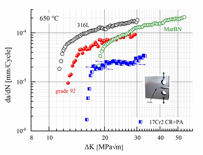
Metals 2020, 10, 463 3 of 22
Metals 2020, 10, x FOR PEER REVIEW 3 of 21
Simplified phase
Figure1.1.Simplified
Figure phase diagrams
diagrams of
of the
the17Cr1/2
17Cr1/2“workhorse”
“workhorse”(nominal:
(nominal:1717
Cr,Cr,
2.62.6
W,W,0.6 0.6
Nb,Nb,
0.250.25
Si)
and the advanced 17Cr5 (nominal: 17 Cr, 4 W, 1 Nb, 0.25 Si) trial steels (Thermo-Calc ® , TCFE7).
Si) and the advanced 17Cr5 (nominal: 17 Cr, 4 W, 1 Nb, 0.25 Si) trial steels (Thermo-Calc®, TCFE7).
According
While it is to these the
known thatlower alloyed “workhorse”
thermodynamic calculation 17Cr1/2 steel (nominal:
overestimates 17 Cr, 2.6
the σ-phase W, 0.6
range in Nb,
this
0.25 Si) contains a volume fraction of about 2.23 vol.% of Laves phase at 650 ◦ C. The increased W- and
alloying system [16], no practical information on the calculation accuracy is available concerning the
Nb-contentsas
α-Cr-phase, offartheasadvanced
the authors 17Cr5 are(nominal:
aware of.17The Cr, calculated
4 W, 1 Nb, chromium
0.25 Si) composition yield of
concentration a more than
the ferrite
doubled volume fraction of 4.82 vol.%. According to the calculation, both
matrix does not drop below 16.5 wt.% in the application temperature range and thus ensures sufficient steels contain small contents
of theoxidation
σ- and α-Cr- ◦ C, respectively.
steam [11]phases below 610
and downtime and 450 [41,42]
corrosion resistance.
While
The two it trial
is known
alloythat
types thermodynamic
are characterized calculation overestimates
by a fundamental the σ-phase
difference: Therange in this alloying
low-alloyed 17Cr1/2
system [16], no practical information on the calculation accuracy is available
workhorse composition represents an alloy, similar to (but not matching) the philosophyα-Cr-phase, concerning the of current
as farsteels,
AFM as thewhich
authors are multi-step
need aware of. The calculated
quality chromium
heat treatment to concentration
reach optimum of strength.
the ferriteInmatrix does
the case of
not drop below 16.5 wt.% in the application temperature range and
AFM steel, this consists of austenitizing with martensitic transformation during subsequent rapid thus ensures sufficient steam
oxidation
cooling and [11]
a and
seconddowntime
(or even corrosion [41,42] resistance.
third) holding step at temperatures (comparatively far) above the
The two trial alloy types are characterized
envisaged application temperature for stress relief by a fundamental
and precipitationdifference: The low-alloyed
heat treatment. With 17Cr1/2
kinetics
workhorse composition represents an alloy, similar to (but not matching) the
being tuned to rapid precipitation HiperFer 17Cr1/2 can either be put into service in the cold-rolled philosophy of current AFM or
steels, which need multi-step quality heat treatment to reach optimum strength.
recrystallized + precipitation heat treated state, or precipitation heat treatment could potentially be In the case of AFM
steel, thisduring
executed consists of austenitizing
plant commissioning with martensitic
(outlined transformation
in Section 2.4). Standardduring subsequent
quality rapid cooling
heat treatment above
application temperature thus becomes obsolete. This batch served as the “workhorse” toenvisaged
and a second (or even third) holding step at temperatures (comparatively far) above the study the
application temperature
fundamental interactionsforof stress relief andprocessing,
chemistry, precipitationprecipitation,
heat treatment. With kinetics
resulting being tunedand
microstructure to
rapid precipitation HiperFer 17Cr1/2 can either be put into service in
mechanical properties. The gained know-how then was transferred to the advanced 17Cr5 variant, the cold-rolled or recrystallized +
precipitation heat treated state, or precipitation heat treatment could potentially
which is designed for age-hardening and thus redundantizes any standard quality and even simplified be executed during
plant commissioning
precipitation heat treatment(outlined in Section
(additional 2.4). Standard for
to recrystallization quality
grainheat
size treatment
adjustment) above
after application
the forming
temperature thus becomes obsolete. This batch served as the
process. The increase in tungsten content reduces primary creep strain by increased “workhorse” to study the fundamental
solution
interactions of chemistry, processing, precipitation, resulting microstructure
strengthening, while the higher content of niobium boosts precipitation kinetics and thus minimizes and mechanical properties.
The gained know-how
accumulation of creep strain thenduring
was transferred
decomposition to the ofadvanced 17Cr5 variant,
the supersaturated which isand
solid solution designed for
nucleation
age-hardening and thus redundantizes any standard quality
of the strengthening Laves phase precipitates in the early primary creep stage. and even simplified precipitation heat
treatment (additional to recrystallization for grain size adjustment) after the forming process. The
increase
2.2. in tungsten
Base Material contentProcessing
Production, reduces primary creep strain by increased solution strengthening, while
and Picrostructure
the higher content of niobium boosts precipitation kinetics and thus minimizes accumulation of creep
The model steels were produced by the Steel Institute (IEHK) of the Northrhine-Westfalian
strain during decomposition of the supersaturated solid solution and nucleation of the strengthening
Technical University Aachen (RWTH), Germany from high purity raw materials by vacuum induction
Laves phase precipitates in the early primary creep stage.
melting of 80 kg ingots and casting to original block dimensions of 140 mm × 140 mm × ~ 525 mm. The
blocks were then forged to 80 mm × 56 mm, air cooled and cut into pieces of 135 mm in length.
Subsequently soaking was carried out at 1140–1180 °C for 2 h. The 17Cr1 blocks were hot-rolled to a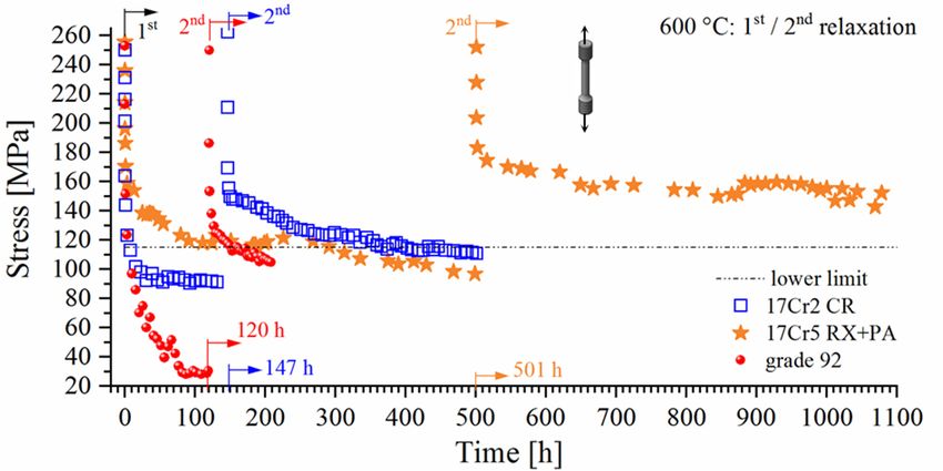
Metals 2020, 10, 463 4 of 22
2.2. Base Material Production, Processing and Picrostructure
The model steels were produced by the Steel Institute (IEHK) of the Northrhine-Westfalian
Technical University Aachen (RWTH), Germany from high purity raw materials by vacuum induction
melting of 80 kg ingots and casting to original block dimensions of 140 mm × 140 mm × ~ 525 mm.
The blocks were then forged to 80 mm × 56 mm, air cooled and cut into pieces of 135 mm in length.
Metals 2020, 10, x FOR PEER REVIEW 4 of 21
Subsequently soaking was carried out at 1140–1180 ◦ C for 2 h. The 17Cr1 blocks were hot-rolled to a
final ◦ C and subsequently air-cooled, while the 17Cr2 material was
final plate
plate thickness
thicknessof of15.5
15.5mm
mmatat1000
1000 °C and subsequently air-cooled, while the 17Cr2 material was
cold-rolled ◦
cold-rolled 920 °C and subsequently water quenched.
920 C and subsequently water quenched.
Hot-rolling
Hot-rolling (referred
(referred to to as
as “HR”
“HR” ininthe
thefollowing
followingtext)
text)above
abovethe
thedissolution
dissolution temperature
temperature of of
the
the Laves phase in combination with comparably slow air cooling leads
Laves phase in combination with comparably slow air cooling leads to almost globular grain to almost globular grain
morphology
morphology with with lowlow dislocation
dislocationdensity
densityand
andfew,
few,small
small Laves
Laves phase
phase particles,
particles, mainly
mainly located
located at
at high
high
angleangle
graingrain boundaries
boundaries (Figure
(Figure 2a).2a).
In In contrast,cold-rolling
contrast, cold-rolling(“CR”
(“CR” inin the
the following)
following)below
belowthe the
dissolution temperature of the Laves phase, followed by rapid water quenching,
dissolution temperature of the Laves phase, followed by rapid water quenching, results in a typical results in a typical
deformation
deformation morphology
morphology with with elongated
elongated grains
grains(Figure
(Figure2b),
2b),high
highdislocation
dislocationdensity
densityandandrarely
rarelyanyany
Laves
Laves phase
phase particles.
particles. Globular
Globular grain
grain morphology
morphology can canbebeobtained
obtainedby byrecrystallization
recrystallizationannealing
annealing
above
above the
the Laves
Laves phase
phasedissolution
dissolutiontemperature.
temperature.To Toobtain
obtainequi-axed,
equi-axed,globular
globulargrain
grainstructure
structureand
andfull
full
dissolution
dissolution of Laves phase particles (originating from preceding forming), the rolled 17Cr2 plateswere
of Laves phase particles (originating from preceding forming), the rolled 17Cr2 plates were
annealed ◦ C for 15 min and subsequently water quenched. 1100–1125 ◦ C for 25 min were
annealedat at1025–1050
1025–1050 °C for 15 min and subsequently water quenched. 1100–1125 °C for 25 min were
applied
applied inin case
case of
of the
the 17Cr5
17Cr5 plates.
plates.
(a) (b)
Figure 2.
Figure 2. Typical
Typicalmicrostructures
microstructuresof
of(a)
(a)hot-rolled
hot-rolled17Cr1
17Cr1and
and(b)
(b)cold-rolled
cold-rolled17Cr2
17Cr2HiperFer
HiperFersteel
steel(R:
(R:
Rolling,T:
Rolling, T:Transversal,
Transversal,N:
N:Normal
Normaldirection
directionofofrolled
rolledplate
platematerial;
material;obtained
obtainedfrom
fromoptical
opticalmicrographs
micrographs
taken from the three directions).
taken from the three directions).
The chemical
The chemical compositions
compositions ofofthe
thetrial
trialsteels
steels(analyzed
(analyzedby byInductively
InductivelyCoupled
CoupledPlasma
PlasmaOptical
Optical
Emission Spectroscopy
Emission Spectroscopy (ICP-OES);
(ICP-OES);C,C,NN analyzed
analyzed bybyinfrared
infraredabsorption) and and
absorption) commercial
commercial316L,316L,
grade
92, MarBN
grade (from (from
92, MarBN original material
original certificates)
material are given
certificates) in Table
are given 1.
in Table 1.
Commercial grade 92 (1040–1070 ◦ C, 2 h / 730–800 ◦ C, 2 h) material was supplied in the form
Table 1. Chemical
of billet (diameter: 200 mm),composition
MarBN (1120 ◦ C/1
(wt.-%) of the
h/airferritic trial +
cooling alloys ◦ C/2
700 and benchmark steels.+ 700 ◦ C/4
h/air cooling
h/air cooling) in slab
Batch-ID: C form N Cr × 200
of 100 mm Mnmm Si × 68 mm Nb dimension
W Vand 316L
Al as sheet
Ni product
Mo ofB16
mm thickness.
HiperFer 17Cr1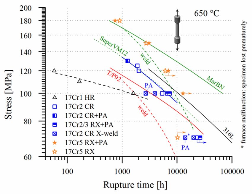
Metals 2020, 10, 463                                                                                        5 of 22

              Table 1. Chemical composition (wt.-%) of the ferritic trial alloys and benchmark steels.

      Batch-ID:         C        N       Cr     Mn      Si     Nb      W      V      Al      Ni     Mo      B
  HiperFer 17Cr1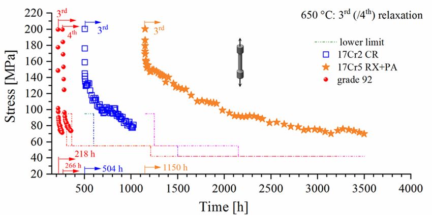
Metals 2020, 10, 463                                                                                 6 of 22

2.5. Mechanical Testing
      For tensile, creep and relaxation testing cylindrical specimens with gauge diameters of 6.4 mm
and gauge lengths of 30 mm were applied. All samples for mechanical testing were taken from the
plate materials perpendicular to the rolling direction.
      The tensile experiments were performed at strain rates of 10−3 s−1 at ambient (according to DIN
EN 10002-1) and 8.33·10−5 s−1 /8.33·10−4 s−1 (in the elastic/plastic range, according to DIN EN 10002-5)
at elevated temperatures, utilizing an Instron (Norwood, MA, USA) Type 1362 testing machine with
10 kN of load capability.
      Creep experiments were carried out in single specimen, constant load, lever-arm type creep
machines, with continuous elongation measurement at the gauge portions of the specimens. In case
of specimens tested at stress levels below 100 MPa only the primary creep stages were recorded in
single specimen machines. Upon entering the secondary stage of creep the samples were transferred
to multi-specimen machines for long-term testing (unless otherwise stated) in discontinuous creep
experiments with periodical measurement of specimen strain. Optical strain measurements were
carried out after cooling to ambient temperature, unloading and taking the specimens from the testing
equipment for length measurement. This procedure was repeated in nominally 1000 h intervals until
rupture. Electrical three-zone furnaces, controlled to the specified testing temperatures with an accuracy
of +/− 2 ◦ C, were used in the tensile and single specimen creep experiments. The multi-specimen
machines for discontinuous creep testing were equipped with electrical five-zone furnaces, controlled
to an accuracy of +/− 3 ◦ C.
      Relaxation experiments were executed utilizing an Instron Type 1362 testing machine with 10 kN
of load capability. At testing temperature, the specimens were loaded to the initial stress level (250 MPa
@ 600 and 200 MPa @ 650 ◦ C), applying a controlled strain rate of 10−3 s−1 . The relaxation then was
initiated by switching the machine to strain control. While the strain level reached after loading was
kept constant stress relaxation was recorded.
      Type R (Pt/RhPt) thermocouples were attached to the specimen gauge lengths for temperature
control in tensile tests and continuous creep testing, while shielded (Type R) temperature measuring
rods, in close vicinity to the specimens, were utilized in interrupted creep testing. In tensile, creep and
relaxation testing all specimens were heated to the designated testing temperature at a rate of 5 K/min.
and maintained for about one hour before starting the testing machine or applying the load for ensuring
thermal equilibrium conditions.
      According to the European Code-of-Practice [48] strain controlled thermomechanical fatigue
(TMF) testing was executed at cylindrical specimens with a gauge length of 15 mm and a diameter of
7 mm, utilizing servo-hydraulic fatigue testing systems with inductive specimen heating. Type R sling
thermocouples were utilized to control temperature. A so called “out-of-phase cycle (oop)” was started
by heating from the minimum temperature of 50 ◦ C to 650 ◦ C maximum temperature at a controlled
rate of 10 Ks−1 . After reaching the maximum temperature the specimen was immediately cooled down
at the same rate (10 Ks−1 ) by compressed air, i.e., no holding times were implemented into the cycle,
to restrict creep to a minimum. During heating and cooling the thermal expansion of the material was
either fully (100% oop) or partly (80, 60, 45% oop) obstructed by the testing machine. Below ~ 150 ◦ C,
cooling was retarded due to insufficient amounts of cooling air. For this reason, the duration of the
cooling cycle was 85 s. The duration of the whole cycle was 145 s.
      Fatigue crack growth (FCG) experiments at compact tension (CT) specimens were accomplished
utilizing a servo-hydraulic Instron (Norwood, Massachusetts, USA) Model 1343 testing machine with
inductive heating. A modified specimen geometry (width, W: 40 mm, thickness, B: 10 mm, machined
notch depth, an : 10 mm) was utilized, because of limited material availability. The dimensions are in
accordance with the ASTM fatigue crack growth testing standard [49]. Pre-cracking of the specimens
up to a starter crack length a0 to width ratio (a/W) of 0.4 was performed at ambient temperature in an
Instron Model 1603 resonance tester. The direct current potential drop (PD) technique was employed to
record crack length during the FCG experiments. Sinusoidal waveform at constant load ratio (R = 0.1)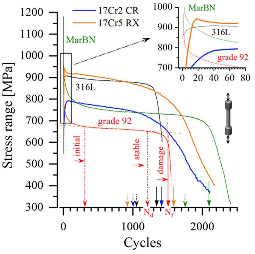
Metals 2020, 10, 463                                                                                  7 of 22

was applied until the termination criterion of a/W = 0.7 was reached. The cyclic stress intensity factor
(∆K) was determined following the method specified in ASTM E647 [49]. The cyclic crack growth rate
was evaluated by the 7-point polynomial method proposed by ASTM E647 [49].
     A Zwick Roell (Ulm, Germany) 50 J miniature hammer was utilized in impact testing of 27 mm
× 3 mm × 4 mm KLST specimens (60◦ notch angle, 1 mm depth, notch radius R = 0.1 mm, distance
between anvils: 22 mm), because of limited material availability. A conversion function was established
by comparison of DIN V and KLST impact energy results of solution-annealed material, following the
procedure outlined by Schill et al. [50].

2.6. Microstructural Investigation
     Specimens for the investigation of initial microstructure were electrically discharge machined
(EDM) from the plate materials. For metallographic characterization the specimens were mounted in
epoxy resin, ground and polished to a sub-micron finish in colloidal silica suspension and Al2 O3 in
dilute KOH solution for approx. 4 h and subsequently electrolytically etched at 1.5 V in 5% H2 SO4
to enhance the particle/matrix contrast and to increase discriminability of the smallest (< 30 nm),
very closely located particles. Characterization was accomplished by light optical (Leica MEF4,
Wetzlar, Germany) and scanning electron microscopy with energy and/or wavelength dispersive X-ray
spectroscopy (Zeiss Merlin, Oberkochen, Germany) / Oxford Instruments Inca/Wave (Abingdon, UK)).

3. Results and Discussion

3.1. Tensile Strength
       The tensile strength of hot-rolled 17Cr1 plate material is comparatively low (cf. 17Cr1 HR in
Figure 3a), when directly compared to ferritic-martensitic steel [51]. Rolling at lower temperature
(i.e., below the dissolution temperature of the Laves phase) leads to a moderate rise in tensile strength
in case of the cold-rolled 17Cr2 batch (cf. 17Cr2 CR in Figure 3a).
       By heat treatment (cf. 17Cr2 RX + PA in Figure 3a), almost doubled ambient temperature tensile
strength values are obtainable in case of the workhorse alloy. In the advanced 17Cr5 trial steel the
increased W and Nb-contents cause increased tensile strength by improved solid solution hardening
already in the recrystallized state (cf. Figure 3b: RX). After precipitation annealing the yield and tensile
strength values, as well as rupture elongation (~15% at ambient, > 25% at high temperature), approach
the range of AFM steels (cf. Figure 3b: RX + PA, exemplary microstructure in Figure 4) [52].
       As a summary it can be stated, that simple precipitation annealing mainly yields strongly increased
ultimate tensile and moderately improved yield strength values. If further enhanced yield strength is
desired, increased dislocation density (e.g., induced by thermomechanical processing) is a measure
of choice. There are obviously several effective ways to adjust the short-term mechanical properties
within this alloying system. The optimum way apparently depends on the designated application,
which dictates the details of material specification.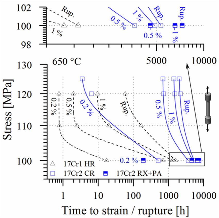
3.1. Tensile Strength
                     The tensile strength of hot-rolled 17Cr1 plate material is comparatively low (cf. 17Cr1 HR in
                Figure 3a), when directly compared to ferritic-martensitic steel [51]. Rolling at lower temperature (i.e.
                below the dissolution temperature of the Laves phase) leads to a moderate rise in tensile strength in
Metals 2020, 10,case
                 463 of the cold-rolled 17Cr2 batch (cf. 17Cr2 CR in Figure 3a).                                                      8 of 22

                                                                                        Rupture elongation [%]
                                                                                       T [°C]      AT    550        650
                                                                                     17Cr1 HR      26.1 24.6        29.1
                                                                                     17Cr2 CR      22.9 23.4        24.8
                                                                                   17Cr2 RX + PA 19.7 20.3          23.4

                                                                    (a)

                                                                                        Rupture elongation [%]
                                                                                       T [°C]      AT    550   650
                                                                                     17Cr5 RX      25.6 17.6 22.7
                                                                                   17Cr5 RX + PA 14.1 14.8 19.1

                                                                    (b)
         Metals 2020, 10, x FOR PEER REVIEW                                                                                8 of 21
      Figure 3. Tensile strength values of (a) the hot-rolled (HR) 17Cr1, the cold-rolled (CR), recrystallized
        increased
      and           W andannealed
           precipitation    Nb-contents      cause increased
                                         (RX+PA)     17Cr2 and    tensile
                                                                     (b) thestrength  by improved
                                                                               recrystallized     (RX) solid   solution hardening
                                                                                                         and recrystallization      and
        already  in the recrystallized
      precipitationFigure
                     annealed             state (cf. Figure   3b:  RX).  After  precipitation
                                 (RX+PA) 17Cr5 trial steels (AT: ambient temperature).           annealing    the  yield   and tensile
                          3. Tensile strength values of (a) the hot-rolled (HR) 17Cr1, the cold-rolled (CR), recrystallized
         strength values, as well as rupture elongation (~15% at ambient, > 25% at high temperature), approach
                   and precipitation annealed (RX+PA) 17Cr2 and (b) the recrystallized (RX) and recrystallization and
         the range of AFM steels (cf. Figure 3b: RX + PA, exemplary microstructure in Figure 4) [52].
                   precipitation annealed (RX+PA) 17Cr5 trial steels (AT: ambient temperature).

      Figure Figure    4. Exemplary
              4. Exemplary           microstructure
                                microstructure    ofofthe
                                                        therecrystallized
                                                            recrystallized andandprecipitation annealed
                                                                                   precipitation         17Cr517Cr5
                                                                                                    annealed          (RX + PA)
                                                                                                                (RX + PA)
              steel taken
      steel taken    fromfrom   a specimen
                            a specimen      headsection
                                          head   section after
                                                           aftertensile testing
                                                                  tensile       (cumulated
                                                                            testing          time from
                                                                                     (cumulated         600from
                                                                                                     time   to 650600  to 650 ◦ C:
                                                                                                                  °C: 2.75
              h): Small, evenly distributed, intragranular Laves phase precipitates, almost fully covered grain
      2.75 h): Small, evenly distributed, intragranular Laves phase precipitates, almost fully covered grain
              boundaries with alongside formation of characteristic particle free zones (PFZ).
      boundaries with alongside formation of characteristic particle free zones (PFZ).
              As a summary it can be stated, that simple precipitation annealing mainly yields strongly
         increased ultimate tensile and moderately improved yield strength values. If further enhanced yield
         strength is desired, increased dislocation density (e.g. induced by thermomechanical processing) is a
         measure of choice. There are obviously several effective ways to adjust the short-term mechanical
         properties within this alloying system. The optimum way apparently depends on the designated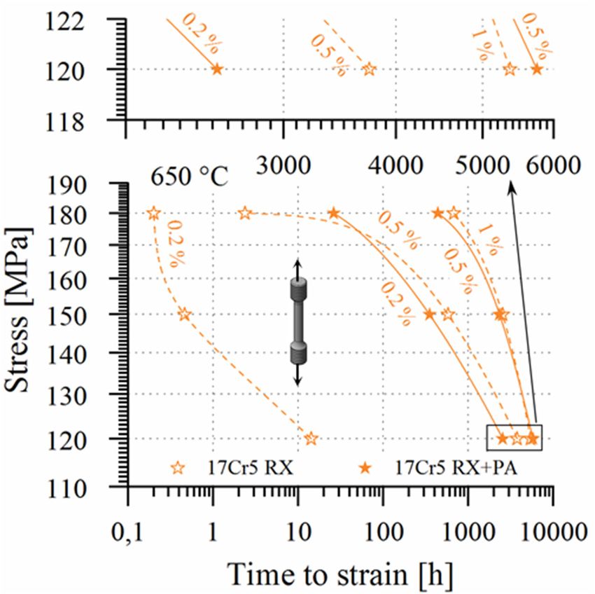
Metals 2020, 10, 463                                                                                  9 of 22

3.2. Short Crack Initiation and Growth: Technical Lifetime in Thermomechanical Fatigue Loading
      The potential performance of material classes in future, flexible operation has not been considered
in an adequate way by the experts yet. Thermomechanical fatigue testing can be considered as most
relevant to practice, when concerning the technical lifetime of thick section components as the most
critical elements in cyclic plant operation. Figure 5a displays typical thermomechanical fatigue life
curves from 100% oop thermomechanical fatigue experiments. The thermal expansion of the specimens
is fully obstructed in a 100 oop cycle by the testing machine, while cycling between 50 and 650 ◦ C,
causing 0.79% of mechanical strain in case of grade 92, 0.76% in case of HiperFer 17Cr2, 1.14% in
case of 316L, 0.75% in case of MarBN and 0.73% in case of HiperFer 17Cr5 steel. Ferritic-martensitic
steels (Figure 5a: grade 92, MarBN) exhibit high initial stress range, due to initially high intrinsic
dislocation density. During an “initial phase” (approx. 300 cycles in case of grade 92, 700 cycles in
case of MarBN), however, the recorded stress range drops by typically one third and the material
enters a quasi-“stable” phase of slightly negative slope, which is accompanied by polygonization of
the martensite lath structure [18].
      Finally, the materials reach the “damage phase”, which in AFM steel is characterized by a
comparatively steep drop in stress range until final failure. Austenitic steel behaves the opposite way:
Because of higher thermal expansion and strength at elevated temperature, it hardens in the initial
phase, reaches higher stable stress range, but fails rapidly after damage initiation. Ferritic HiperFer
behaves like austenitic steel in terms of cyclic hardening, but the microstructural mechanisms do
differ: While in austenite initial strengthening is an effect of cyclic strain hardening, it is intensified
by permanent “thermomechanically triggered precipitation” strengthening by Laves phase particles
in HiperFer, which is boosted by increased dislocation density. (Cyclic) Plastic deformation not only
accelerates precipitation, but furthermore refines particles (cf. Figure 6, in comparison to Figure 4).
      Based on this mechanism it reaches stress ranges higher than AFM steel (17Cr2 > grade 92, 17Cr5
> MarBN), approximately on the 316L level (17Cr5) and exhibits comparatively forgiving damage and
failure behavior (Figure 5a). Taking into account the outlined differences of the materials, the technical
lifetime was determined from the intersection of linear approximations to the “stable” and the “damage”
curve sections of the fatigue curves (cf. “Nf ”, grade 92 curve in Figure 5a). The onset of damage was
assessed by deviation of the fatigue curve from a linear approximation to the stable curve section (cf.
“Nd ”, grade 92 curve in Figure 5a). Relating technical lifetime Nf and damage initiation Nd (Table 2) to
each other, demonstrates the more forgiving failure character of the HiperFer alloys, particularly of the
17Cr5 variant, concerning propagation of short cracks.
      Thermo-mechanical fatigue life behavior in out-of-phase cycles of varying thermal strain
obstruction (from complete, i.e., εmech. = 100% to 45% of εth. ) of the HiperFer trial alloys,
ferritic-martensitic grades 92 and MarBN as well as austenitic 316L steel is depicted in Figure 5b.
In comparison to grade 92, HiperFer 17Cr2 reaches almost doubled TMF lifetime over the entire
span of stress (i.e., strain) ranges. With the lifetime of the recrystallized + precipitation annealed
material falling close to the same main line the initial heat treatment state does not play a significant
role. MarBN-type steel achieves about twice the number of loading cycles compared to the HiperFer
workhorse grade (17Cr2). In the high-alloy version 17Cr5 precipitate volume fraction and thus strength
and reactive hardening has been maximized. In comparison to grade 92 up to 5.5 (to MarBN 2.5 times)
longer technical fatigue life is obtainable over the entire stress range, while at high stress ranges it even
matches the performance of austenitic 316L (cf. Figure 5a).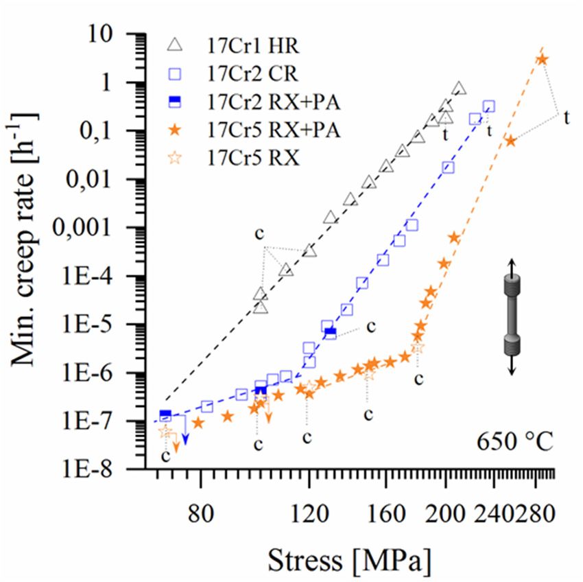
Metals 2020, 10, 463                                                                                                                   10 of 22
Metals 2020, 10, x FOR PEER REVIEW                                                                                                     9 of 21

                                                                      (a)

                                                                     (b)
     Figure
     Figure 5.
             5. Thermo-mechanical
                 Thermo-mechanicalfatigue    fatiguetesting results
                                                      testing  results ofofferritic trial,
                                                                              ferritic     commercial
                                                                                       trial,  commercial   ferritic-martensitic
                                                                                                                ferritic-martensitic   and
     austenitic  steels (50–650   °C,  ε
     and austenitic steels (50–650 C, εmech. = −0.45 to −1εth. , 10 Ks , no holding times at Tmin. and Tmax. ).
                                        ◦mech. = −0.45 to −1ε th. , 10 Ks           −1
                                                                          −1, no holding    times   at  T min. and   T max. ). (a) Typical
     fatigue life curves
     (a) Typical   fatigueinlife
                              100curves
                                  % out-of-phase       cycles (εmech. = cycles
                                            in 100% out-of-phase         -εth.) and
                                                                                  (εmech.   = -εth. ) and
                                                                                     (b) technical    lifetime
                                                                                                             (b) over    half-life
                                                                                                                  technical          stress
                                                                                                                                 lifetime
     range (i.e. as astress
     over half-life    resultrange
                               to differing
                                     (i.e., asobstruction   of thermal
                                                a result to differing        strain, εmech.
                                                                        obstruction            −0.45 εth.
                                                                                         of =thermal       to −εth.
                                                                                                        strain,     ).
                                                                                                                  εmech.    = −0.45 εth.
      to −εth. ).
    Finally, the materials reach the “damage phase”, which in AFM steel is characterized by a
comparatively steep drop in stress range until final failure. Austenitic steel behaves the opposite way:
Because of higher thermal expansion and strength at elevated temperature, it hardens in the initial
phase, reaches higher stable stress range, but fails rapidly after damage initiation. Ferritic HiperFer
behaves like austenitic steel in terms of cyclic hardening, but the microstructural mechanisms do differ:
While in austenite initial strengthening is an effect of cyclic strain hardening, it is intensified by
permanent “thermomechanically triggered precipitation” strengthening by Laves phase particles in
Metals 2020, 10, x FOR PEER REVIEW 10 of 21
HiperFer, which
Metals 2020, 10, 463 is boosted by increased dislocation density. (Cyclic) Plastic deformation not only
11 of 22
accelerates precipitation, but furthermore refines particles (cf. Figure 6, in comparison to Figure 4).
Figure
Figure6.6.Exemplary
Exemplarymicrostructure
microstructure from
from aa 17Cr5 TMF (parameters
17Cr5 TMF (parameters cf.cf. Figure
Figure 5a
5a specimen
specimen(experiment
(experiment
initiated
initiatedfrom
from RX
RX state,
state, interrupted
interrupted after
after 1000 cycles, i.e.,
1000 cycles, i.e. cumulated
cumulated time
time from 600 to
from 600 to 650
650 ◦°C: 2.5 h):
C: 2.5 h):
Refined intragranular Laves phase precipitates, reduced particle free zone (PFZ) width (cf. Figure
Refined intragranular Laves phase precipitates, reduced particle free zone (PFZ) width (cf. Figure 4). 4).
Based on this mechanism it reaches stress ranges higher than AFM steel (17Cr2 > grade 92, 17Cr5
Table 2. Half-life stress range, technical TMF lifetime Nf , damage initiation Nd and damage ranges
> MarBN), approximately on the 316L level (17Cr5) and exhibits comparatively forgiving damage and
(50 −650 ◦ C, εmech. = −εth , 10 Ks−1 , no holding times at Tmin. and Tmax. ).
failure behavior (Figure 5a). Taking into account the outlined differences of the materials, the technical
lifetime was determined Material:
from the intersection
σ@Nf/2 of Nlinear
d Napproximations
f Damage Range to the "stable" and the
"damage" curve sections of the fatigue
HiperFer 17Cr2 CR curves
760 (cf. “N
974f”, grade 92 curve in Figure 5a). The onset of
1389 29.9%
damage was assessed by deviation of the fatigue curve from a linear approximation to the stable curve
HiperFer 17Cr5 RX 886 1031 1569 34.2%
section (cf. “Nd”, grade 92 curve in Figure 5a). Relating technical lifetime Nf and damage initiation Nd
Grade 92 662 1247 1502 17.0%
(Table 2) to each other, demonstrates the more forgiving failure character of the HiperFer alloys,
MarBNconcerning760
particularly of the 17Cr5 variant, 1768 of
propagation 2080 15.0%
short cracks.
316L 884 1143 1326 13.8%
Table 2. Half-life stress range, technical TMF lifetime Nf, damage initiation Nd and damage ranges (50
3.3. Fatigue εmech. =Propagation:
−650 °C,Crack −εth, 10 Ks−1, no holdingLifetime
Residual times at Tmin. and Tmax.).
In comparison to grade Material:
92 (Figure 7) σ@N f/2
it takes Nd timesN(to
1.25 f
316LDamage range
1.4 times) the stress intensity to
HiperFer 17Cr2 CR 760 974 1389 29.9%
initiate propagation of pre-existing cracks in HiperFer 17Cr2 (RX + PA), while MarBN even ranges
HiperFer 17Cr5 RX 886 1031 1569 34.2%
slightly higher. Nevertheless stable crack propagation is at least half an order of magnitude faster in
Grade 92 662 1247 1502 17.0%
both the AFM steels and 316L, with rising advantage of HiperFer towards increasing stress intensity.
MarBN 760 1768 2080 15.0%
Obviously, HiperFer does not
316L
display a classical
884
“Paris-Erdogan”
1143 1326
[53,54]
13.8%
regime of positive linear
proportionality of crack growth velocity (da/dN) to rising stress intensity (∆K) in a double logarithmic
Thermo-mechanical
representation (Figure 7). Itfatigue life behavior
rather reflects in out-of-phase
staircase-like curve shape cycles of varying
with plateau regionsthermal strain
of constant, to
obstruction (from complete, i.e. ε = 100% to 45% of ε ) of the HiperFer
some extent even slightly negative proportionality (indicated by the dashed-dotted lines, inserted into
mech. th. trial alloys, ferritic-
martensitic
the HiperFergradesgraph in 92Figure
and MarBN
7). Crack aspropagation
well as austeniticin HiperFer 316L steel
thus is depicted
remains in Figure
at a constant, 5b. In
sometimes
comparison
even decreasing,to grade 92, HiperFer
velocity 17Cr2 reaches
over a comparatively almost
wide rangedoubled TMF lifetime
of the cyclic over the
crack growth entire
curve, spanof
despite of
stress (i.e. strain) ranges.
increasing stress intensity. With the lifetime of the recrystallized + precipitation annealed material falling
close The
to the same main
proposed linefor
reason thethis
initial heat treatment
behavior state does
is a combination of not play aprecipitation
“reactive significant role. MarBN-type
strengthening”,
steel achieves
outlined in theabout twicesection,
previous the number with of loading
several cycles
other compared
aspects: to the HiperFer
The material workhorse
“dynamically” grade
hardens,
(17Cr2). In the high-alloy version 17Cr5 precipitate volume fraction and thus
because of cyclic, plastic material distortion in front of the crack tip, what aggravates crack propagation. strength and reactive
hardening has been maximized.
Another contribution stems fromInlow-angle
comparison to boundaries,
grain grade 92 upevolving to 5.5 (toinMarBN 2.5 zone
the plastic times)inlonger
front
technical fatigue life is obtainable over the entire stress range, while
of the crack tip (cf. sub-grain formation, caused by accumulated creep deformation, in PFZs of crept at high stress ranges it even
matches the performance of austenitic 316L (cf. Figure 5a).
specimens, cf. Section 3.4.1, Figure 11) and rapidly becoming decorated by Laves phase particles,
which frequently lead to crack branching and thus dissipation of energy away from the main crack
path. Pre-existing high angle grain boundaries, covered by Laves phase particles, act in the same way.3.3. Fatigue Crack Propagation: Residual Lifetime
In comparison to grade 92 (Figure 7) it takes 1.25 times (to 316L 1.4 times) the stress intensity to
initiate propagation of pre-existing cracks in HiperFer 17Cr2 (RX + PA), while MarBN even ranges
slightly
Metals higher.
2020, 10, 463 Nevertheless stable crack propagation is at least half an order of magnitude faster12 of 22in
both the AFM steels and 316L, with rising advantage of HiperFer towards increasing stress intensity.
Obviously, HiperFer does not display a classical “Paris-Erdogan” [53,54] regime of positive linear
A crack tip getting arrested at obstacles like particle clusters, (newly created) low- or (pre-existing)
proportionality of crack growth velocity (da/dN) to rising stress intensity (ΔK) in a double logarithmic
high-angle grain boundaries, causes increased stress intensity, in turn rising plastic distortion and
representation (Figure 7). It rather reflects staircase-like curve shape with plateau regions of constant,
consequently boosted precipitation, until a certain threshold is overcome and the crack tip breaks loose.
to some extent even slightly negative proportionality (indicated by the dashed-dotted lines, inserted
It may
into further
the be assumed,
HiperFer graph inthat repetition
Figure of this
7). Crack mechanismin
propagation causes the staircase-like
HiperFer thus remains curve
at ashape in
constant,
contrast to a classical Paris-Erdogan behavior. The detailed mechanism is not yet fully understood
sometimes even decreasing, velocity over a comparatively wide range of the cyclic crack growth curve, and
still under
despite investigation.
of increasing stress intensity.
Figure 7. Cyclic crack growth curves (650 ◦ C, f = 20 Hz, R = 0.1) of grade 92, MarBN, 316L and HiperFer
Figure 7. cyclic crack growth curves (650 °C, f = 20 Hz, R = 0.1) of grade 92, MarBN, 316L and HiperFer
17Cr2 (CR + PA).
17Cr2 (CR + PA).
3.4. Creep
The proposed reason for this behavior is a combination of “reactive precipitation strengthening”,
3.4.1. Characteristics:
outlined Low-vs.
in the previous High-Alloying
section, Variant
with several other aspects: The material “dynamically” hardens,
because of cyclic, plastic material distortion in front of the crack tip, what aggravates crack
The hot-rolled, low-alloy variant 17Cr1 yields comparably poor creep strength at intermediate
propagation. Another contribution stems from low-angle grain boundaries, evolving in the plastic
and high creep stresses (> 100 MPa; cf. 17Cr1 HR in Figures 8–10), because of low dislocation density
zone in front of the crack tip (cf. sub-grain formation, caused by accumulated creep deformation, in
and a lack of strengthening precipitates, when put into service in the hot-rolled state. Nevertheless, it
PFZs of crept specimens, cf. subsection 3.4.1, Figure 11) and rapidly becoming decorated by Laves
obviously approaches the grade 92 level at practically more relevant testing stresses lower than 100 MPa
phase particles, which frequently lead to crack branching and thus dissipation of energy away from
(Figure 10). Cold-rolling not only yields increased tensile (cf. 17Cr2 CR in Figure 3a), but diminished
the main crack path. Pre-existing high angle grain boundaries, covered by Laves phase particles, act in
minimum creep rate (Figure 9) and boosted creep rupture strength (Figures 8 and 10).
the same way. A crack tip getting arrested at obstacles like particle clusters, (newly created) low- or
In creep, increased dislocation density has a two-fold effect in HiperFer steel: First, it accelerates
(pre-existing) high-angle grain boundaries, causes increased stress intensity, in turn rising plastic
precipitation and second, it sufficiently strengthens the material against creep deformation during
distortion and consequently boosted precipitation, until a certain threshold is overcome and the crack
the precipitation process. In combination, this leads to rapid establishment of a stable precipitate
tip breaks loose. It may further be assumed, that repetition of this mechanism causes the staircase-like
microstructure, reduced strain over the entire (mainly in the primary stage of) creep life (Figure 8a)
curve shape in contrast to a classical Paris-Erdogan behavior. The detailed mechanism is not yet fully
and by this to a leap in creep rupture strength (Figures 8a and 10). A similar effect can be achieved by
understood and still under investigation.
precipitation annealing of recrystallized material (cf. 100 MPa values of 17Cr2 RX + PA in Figure 8a).
Compared to cold-rolling, precipitation annealing after recrystallization leads to increased primary
3.4. Creep
creep strain, but in turn to a slight decrease in minimum creep rate (cf. Figure 9) and finally further
improved creep rupture
3.4.1. Characteristics: life (Figures
Low-vs. 8a and 10).
High-Alloying The higher W/Nb- contents boost solid solution and
Variant
precipitation strengthening in case of the 17Cr5 composition, what in turn provides advanced creep
strength. Except of increased primary stage creep strain (Figure 8b) the material performs almost
comparable, no matter if put into service in the recrystallized (RX) or recrystallized + precipitationMetals 2020, 10, x FOR PEER REVIEW 12 of 21
The hot-rolled, low-alloy variant 17Cr1 yields comparably poor creep strength at intermediate
and high creep stresses (> 100 MPa; cf. 17Cr1 HR in Figures 8–10), because of low dislocation density
and a 2020,
Metals lack 10,
of 463
strengthening precipitates, when put into service in the hot-rolled state. Nevertheless,
13 of 22it
obviously approaches the grade 92 level at practically more relevant testing stresses lower than 100
MPa (Figure 10). Cold-rolling not only yields increased tensile (cf. 17Cr2 CR in Figure 3a), but
annealed (RX
diminished + PA) state
minimum creep(Figures 8b, 9 9)
rate (Figure and 10).
and Effective
boosted age-hardening
creep characteristics
rupture strength thus10).
(Figures 8 and were
achieved and the design goal of 17Cr5 successfully met.
(a)
(b)
Figure
Figure8.8.Impact
Impactofofprocessing
processingand heat-treatment
and state:
heat-treatment Time
state: to strain
Time curves
to strain of hot-rolled
curves 17Cr1,
of hot-rolled cold-
17Cr1,
rolled 17Cr2,
cold-rolled recrystallized
17Cr2, and and
recrystallized precipitation annealed
precipitation annealed 17Cr2
17Cr2(100
(100MPa
MPadata
data available (a),
available only) (a),
recrystallized
recrystallized and
and recrystallization
recrystallization and
and precipitation
precipitation annealed
annealed 17Cr5 steel (b).
In creep, increased dislocation density has a two-fold effect in HiperFer steel: First, it accelerates
precipitation and second, it sufficiently strengthens the material against creep deformation during theprocessing (i.e. mainly initial dislocation density) may practically fade out below a stress level of
approximately 70 MPa (cf. Figure 9: intersection of the extrapolated 17Cr1 HR line towards lower
stress). Below this stress level (i.e. at practically relevant creep stress) / beyond this exposure time the
thermomechanical treatment history is supposed to have no significant influence on creep life
Metals 2020, 10, 463
anymore. 14 of 22
Norton-Bailey
Figure9.9.Norton-Bailey
Figure plot
plot of the
of the model
model steels
steels in different
in different processing
processing andtreatment
and heat heat treatment states
states (650°C;
◦
(650 indexed
C; data indexed byfrom
“t”/“c” from(UTS
tensile (UTS/value)/uniaxial
data by “t”/“c” tensile value) uniaxial creep creep experiments,
experiments, all others
all others from from
stress
stress relaxation
relaxation testing;testing; experiments
experiments marked marked with arrows
with arrows are stillare
instill in progress).
progress).
3.4.2. The change
Creep Ruptureimplemented
Strength in processing, from hot-rolling in case of 17Cr1 to cold-rolled 17Cr2, has
a remarkable impact on the Norton-Bailey relations [55,56] of the steels (Figure 9). In comparison to the
low dislocation density, hot-rolled 17Cr1 material the high dislocation density, cold-rolled 17Cr2 steel
yields minimum creep rates, diminished by at least an order of magnitude over the whole stress range.
The minimum creep rates of recrystallized and precipitation annealed 17Cr2 material fits well into the
data of the cold-rolled steel (Figure 9). High initial dislocation density or precipitation annealing are
obviously very effective in decreasing the minimum creep rates of the low alloyed model steel variant.
Synopsis of the results obtained so far suggests, that the impact of thermomechanical processing
(i.e., mainly initial dislocation density) may practically fade out below a stress level of approximately
70 MPa (cf. Figure 9: intersection of the extrapolated 17Cr1 HR line towards lower stress). Below this
stress level (i.e., at practically relevant creep stress) / beyond this exposure time the thermomechanical
treatment history is supposed to have no significant influence on creep life anymore.
3.4.2. Creep Rupture Strength
In Figure 10 the creep strength of the HiperFer 17Cr2 steels is ranked against various state of the art
power engineering structural grades. Cold-rolled and recrystallization + precipitation annealed (RX +
PA) 17Cr2 surpasses grade 92 [57] and approximately matches the performance of the novel 12 Cr steel
Super VM12 [58]. While creep deformation of intermetallic particle strengthened HiperFer is controlled
by growth of the strengthening Laves phase precipitates [16,47,59,60], creep damage and failure are
mainly related to the accumulation of plastic deformation in PFZs (cf. Figure 11), evolving along high
angle grain boundaries [36,47], in long-term application. Intragranular solid solution strengthening
and particle volume fraction, as well as grain boundary particle coverage, were successfully increased
and PFZ width alongside grain boundaries diminished in the 17Cr5 variant.steel Super VM12 [58]. While creep deformation of intermetallic particle strengthened HiperFer is
controlled by growth of the strengthening Laves phase precipitates [16,47,59,60], creep damage and
controlled by growth of the strengthening Laves phase precipitates [16,47,59,60], creep damage and
failure are mainly related to the accumulation of plastic deformation in PFZs (cf. Figure 11), evolving
failure are mainly related to the accumulation of plastic deformation in PFZs (cf. Figure 11), evolving
along high angle grain boundaries [36,47], in long-term application. Intragranular solid solution
along high angle grain boundaries [36,47], in long-term application. Intragranular solid solution
strengthening and particle volume fraction, as well as grain boundary particle coverage, were
strengthening and particle volume fraction, as well as grain boundary particle coverage,15were
Metals 2020, 10,increased
463 of 22
successfully and PFZ width alongside grain boundaries diminished in the 17Cr5 variant.
successfully increased and PFZ width alongside grain boundaries diminished in the 17Cr5 variant.
Figure 10. Creep rupture
Creeprupture strength
rupturestrength
strengthof of HiperFer
ofHiperFer 17Cr1/2
HiperFer 17Cr1/2 and 17Cr5
17Cr1/2 and
and 17Cr5 in
in comparison
comparison tostate
state ofthe
the artAFM
AFM
Figure10.
Figure 10.Creep 17Cr5 in comparison to
to state of
of the art
art AFM
and austenitic
andaustenitic steels
austeniticsteels (100
steels(100 MPa
(100MPa cross-weld
MPa cross-weld data
cross-weld data courtesy
data courtesy of
courtesy of Y.
of Y. Yamamoto,
Y. Yamamoto, ORNL, USA; comparative
and Yamamoto, ORNL,
ORNL, USA;
USA;comparative
comparative
creep strength
creepstrength data:
strengthdata: grade
data:grade
grade92, 316L [57]; MarBN, mean of [61] and [62]; Super VM12 [58]; experiments
creep 92,92, 316L
316L [57];
[57]; MarBN,
MarBN, mean
mean of [61,62];
of [61] and [62];Super
SuperVM12
VM12[58];
[58];experiments
experiments
marked
marked with
with arrows
arrows are
are still
still in
in progress).
progress).
marked with arrows are still in progress).
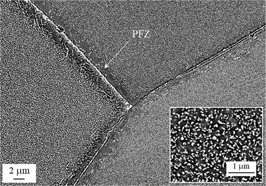
Figure11.
Figure Accumulated plastic
11. Accumulated plastic deformation,
deformation, causing
causing sub-grain
sub-grain formation
formation (cf.
(cf. inlay
inlay micrograph)
micrograph)and
and
Figure 11. Accumulated
associated creep failure plastic
within deformation,
PFZs, locatedcausing
at highsub-grain
angle formation
grain (cf. inlay
boundaries of micrograph)
17Cr5 and
RX material
associated creep failure within PFZs, located at high angle grain boundaries of 17Cr5 RX material (650
associated creep failure
◦ C, 150
(650150 within
tR =h,2720 h, PFZs, located at high angle grain boundaries of 17Cr5 RX material (650
°C, MPa, MPa,
tR = 2720 cf. Figure
cf. Figure 10). 10).
°C, 150 MPa, tR = 2720 h, cf. Figure 10).
The results obtained on this improved alloy variant so far, at least at high stress (150 to
180 MPa; < 150 MPa: in progress), suggest a creep strength on the MarBN-type [61,62] level.
At intermediate stresses (150 to 100 MPa, experiments still in progress) it surpasses austenitic 316L
steel [57]. Nevertheless further data is necessary on lower stress levels.
First, manually produced gas tungsten arc welded (GTAW) joints of cold-rolled base material
were produced, applying chemically identical filler metal strips, taken from the base metal plate. Like
outlined in Section 2.3 these welds intentionally represent the worst-case of deformed (i.e., as-rolled,
forged, bent,) material, being welded and put into service without conventional AFM-like post-weldMetals 2020, 10, 463 16 of 22
heat treatment (PWHT, i.e., annealing above application temperature). At an intermediate stress level
of 100 MPa cold-rolled HiperFer 17Cr2 (CR X-weld) in the as-welded state yields rupture time slightly
below, but performing simplified precipitation annealing (cf. Section 2.4) after welding pushes the
weld above the grade 92 base metal level (PA in Figure 10). At low stress (70 MPa) it outplays welded
grade 92 (including PWHT) by far. The precipitation annealed weld even yielded creep lifetime in
the extrapolated range of MarBN-type welds. Unfortunately, the as-welded 70 MPa creep specimen
was prematurely lost, because of a furnace malfunction. Creep rupture of all the 100 MPa cross-weld
specimens appeared in the weld metal, while the precipitation treated 70 MPa specimen ruptured in the
heat affected zone after 19879 h. The transition in fracture location is subject of further investigation.
Ease of monitoring is mandatory for high temperature structural materials. A combination of
sufficient duration of tertiary creep and rupture deformation is desired. By and large the 17Cr2
(CR and RX + PA states) and 17Cr5 (RX and RX + PA states) alloys obey similar, time-modified
Monkman-Grant [63] relations of time to minimum creep rate to time to rupture [64]. These indicate
that more than 70% of creep life lies within the short secondary and predominantly the tertiary stage of
creep. For this reason, creep life of HiperFer steel can be monitored according to the common codes
of conduct.
3.5. Stress Relaxation
For materials utilized in bolting application resistance to stress relaxation is an important
prerequisite. Figure 12 displays stress relaxation curves of the cold-rolled 17Cr2 and RX + PA 17Cr5
steels in comparison to ferritic-martensitic grade 92. A remaining stress level of 115 MPa after 600 h
of relaxation at 600 ◦ C is a benchmark value to reach for novel materials [65], when initiating stress
relaxation from 250 MPa. With remaining stresses falling below 115 MPa after 7/312 h 17Cr2 CR and
17Cr5 RX + PA fail to reach this criterion in the first relaxation (Figure 12a). Nevertheless, the HiperFer
grades perform remarkably better than grade 92, which drops to about 30 MPa within 87 h, while the
ferritic model steels stabilize at around 95 MPa after 30 h in case of 17Cr2 CR and 468 h in case of 17Cr5
RX+PA. After reloading all the HiperFer materials perform better in the second run. 17Cr2 CR fails the
criterion after another 309 h, while grade 92 after 45 h already. 17Cr5 RX + PA stabilizes well above the
criterion (in a range from 150–160 MPa) for another 600 h. Thermomechanically induced precipitation
of consecutive populations of Laves phase particles upon reloading is argued to be the cause for the
gradual increase in performance of the HiperFer grades.
After termination of the second runs, the specimens were heated to 650 ◦ C under the load level
reached upon termination. A further relaxation run was then started after loading to 200 MPa. At
650 ◦ C the criteria to meet are > 95 MPa after 100 h, > 55 MPa after 1000 h and > 40 MPa after
3000 h (initial stress level: 200 MPa) [65]. The grade 92 specimen fails the 100 h criterion in two
consecutive runs (Figure 12b: after 4/23 h in the 3rd /4th run). In contrast to this 17Cr2 CR meets the
100 h criterion and reaches 78 MPa after another 514 h in the third run. Applying the stress relaxation
rate at termination (0.0266 MPah−1 ) and linearly extrapolating to 1000 h a resulting stress level of 65
MPa would have been reached and the criterion (> 55 MPa) successfully met. The third run of 17Cr5
RX + PA was terminated after 2347 h at a stress level of 70 MPa. By applying the stress relaxation
rate at termination (0.0114 MPah−1 ), it is apparent, that the 3000 h criterion would have been fulfilled.
HiperFer can be thus considered as a potential candidate material for bolting application. Nevertheless,
further investigation into heat treatment, concerning stabilization of early stage relaxation performance
is needed.You can also read