Troubleshooting Guide - CUSTOM FIREPLACES - Copyright 2021 Travis Industries Certified Factory Training Program - Travis ...
←
→
Page content transcription
If your browser does not render page correctly, please read the page content below
CUSTOM FIREPLACES
Troubleshooting Guide

                  Copyright © 2021
Travis Industries Certified Factory Training Program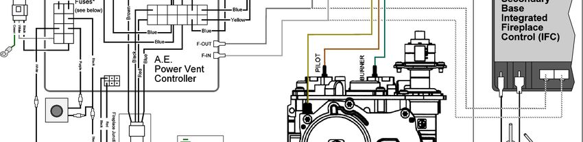
DaVinci Troubleshooting Guide
                                                                                                                                                                         Page 2

Table of Abbreviations ................................................................................................................................................. 3
Overview ...................................................................................................................................................................... 3
Sequence of Operation ................................................................................................................................................ 4
Sequence of Operation - Flow Chart ........................................................................................................................... 5
Troubleshooting Steps ................................................................................................................................................. 6
TouchSmart ............................................................................................................................................................... 10
GreenSmart Troubleshooting - Flow Chart ................................................................................................................ 11
GreenSmart Troubleshooting Cont. ........................................................................................................................... 13
   Continuity Testing Gas Valve ................................................................................................................................. 13
   Voltage Testing Gas Valve ..................................................................................................................................... 13
   Gas Pressure Testing ............................................................................................................................................. 13
SIT Base IFC ............................................................................................................................................................. 14
DaVinci Parts ............................................................................................................................................................. 15
Power Distribution Board ........................................................................................................................................... 18
Where to look for cause of blown fuse(s) .................................................................................................................. 18
DaVinci Aux Power Board Indicators ......................................................................................................................... 19
User Interface Configuration ...................................................................................................................................... 20
Configuration .............................................................................................................................................................. 20
There are 2 configurations – each with its own operating instructions ...................................................................... 20
There are 2 Control Configurations ........................................................................................................................... 20
Wiring Diagram – Pre-TouchSmart............................................................................................................................ 21
Wiring Diagram -              TouchSmart® - Pre-Master Power Switch ............................................................................... 22
Wiring Diagram -              TouchSmart® - Power Switch .................................................................................................. 23
LED Wiring Diagram – Pre-TouchSmart.................................................................................................................... 24

                                                                              17601900 - 6/9/21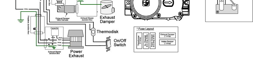
DaVinci Troubleshooting Guide
                                                                                             Page 3
Table of Abbreviations
 IFC      Integrated Fireplace Control                   TS     TouchSmart
 DPB      Power Distribution Board (PDB)                 AUX    Auxiliary Power Board (AUX) (Red
          (Green Board)                                         Board)
 APS      Air Pressure Switch                            REO    Rheostat
 ODAM     Exhaust Damper                                 XMF    Transformer
 IDAM     Intake Damper

Overview
 The DaVinci fireplace has been programmed to have the power exhaust fan purge the
 firebox when power is introduced to the unit. This purge will last 6 minutes. You do
 not have to wait for the purge to end to start the fireplace. The purge process will
 occur after the initial power up and after any power outage.

 The fireplace controls consist of a power distribution control board (PDB) and a base
 Integrated Fireplace Control (IFC) in addition to the power exhaust fan. Additionally,
 there are intake damper(s) and an exhaust damper that is controlled by the PDB.

 When the fireplace is turned on there is a 10-second delay followed by a 30-second pre-
 purge. The Flame Icon LED on newer TouchSmart® Wall Controls (TS) will pulse for
 approximately 50 seconds to show that the unit is in start-up mode. During the delay, the
 exhaust and intake dampers open followed by the power exhaust fan. During the pre-purge,
 the draft produced by the power exhaust fan will activate an air pressure switch (APS)
 signaling to PDB that the fan is operating. After the pre-purge, the IFC will send the signal to
 initiate the start-up sequence.
 The pilot and burner for this fireplace function the same as with all other GreenSmart™ 2
 (GS2) appliances.

 A rheostat controls the speed of the power vent. For 30 seconds the rheostat is bypassed
 sending line voltage to the power exhaust fan. After the purge, the PDB sends the power
 through the rheostat lowering the speed of the power exhaust fan to normal operating speed.

 When the fireplace is turned off the burner and pilot turn off. The power exhaust fan,
 intake, and exhaust dampers remain engaged for 6 minutes (post-purge). After post-purge the
 power exhaust fan turns off, the intake and exhaust dampers close, and the APS switch opens.
 The dampers will remain closed until a start sequence is initiated or if power is lost and
 reinstated (goes into pre-purge then to ready state). In the event of a power failure, the
 exhaust damper will fail “OPEN”.

                                          17601900 - 6/9/21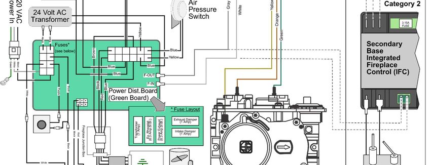
DaVinci Troubleshooting Guide
                                                                                               Page 4
Sequence of Operation
  1) Power Application
       a. Applying 120 volts to the system (plugging in, or return of power from an outage).
  2) “Power Pre-Purge” (6-minute duration)
        a. 24 Volts applied to (1) exhaust damper and intake damper(s).
        b. Rheostat voltage is applied to the Power Exhaust Fan, Air Pressure Switch closes from
           pressure in the flue.
  3) Post “Power Pre-Purge” (after 6 minute Pre Purge)
        a. Voltages removed from all Dampers and Fan(s), system in “Ready” mode (Green LED in the
           center of Power Distribution Board [PDB]).
  4) Switch signal “ON” - Call for FLAME
        a. 24 Volts applied to Exhaust Damper and Intake Damper(s).
        b. The green LED light (in the center of the Power Distribution Board [PDB]) turns
           Yellow/Orange.
        c. After a 10 second delay, the rheostat shunt actuates for 30 seconds sending 120 volts to
           Power Exhaust Fan.
        d. Pressure Switch closes from Pressure in the flue.
  5) On units with TouchSmart® controls, the Wall Control goes to sleep after 15 seconds. The
     flame icon LED will pulse for approximately 50 seconds on newer controls.
  6) After 40 seconds the Rheostat kicks in and the Power Exhaust Fan is ramped down.
  7) Spark at Pilot (15+ seconds) (Dampers/Fan continue to run)
  8) Integrated Fireplace Control (IFC) allows gas to the Pilot
  9) Flame at Pilot
  10) IFC senses rectification of Pilot and allows gas to Burner
  11) Flame at burner
  12) Switch signal “OFF” (any point while burning)
  13) Burner and Pilot flame turn off
  14) Post-Purge (6 minutes)
         a. Exhaust Damper and Intake Damper(s) remain open.
         b. The Power Exhaust Fan continues to operate.
  15) End of Post Purge (after 6 minutes) return to “Ready” state
         a. Voltages removed from all dampers and fans,
         b. Air Pressure Switch opens from lack of pressure (or draft) in the flue.
         c. The system is now in “Ready” mode.
         d. LED light (in the center of the Power Distribution Board [PDB]) is green.

                                             17601900 - 6/9/21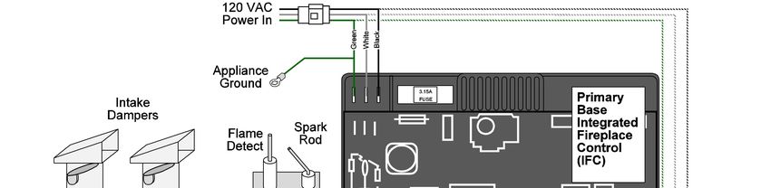
DaVinci Troubleshooting Guide
                                                                                                             Page 5
Sequence of Operation - Flow Chart

                                          DaVinci Troubleshooting
The DaVinci Fireplace is different from a naturally vented appliance, there are several processes that take place
simultaneously. This is important to remember when troubleshooting these fireplaces. When the fireplace is
switched on or the call for flame is made, these (3) things happen almost simultaneously:
                             1) Exhaust damper opens
                             2) Intake damper opens (if installed)
                             3) After 10 seconds the Power Exhaust Fan starts
Next, the APS activates and approximately 40 seconds after the call for flame the rheostat takes control of the
exhaust fan.

                                                  17601900 - 6/9/21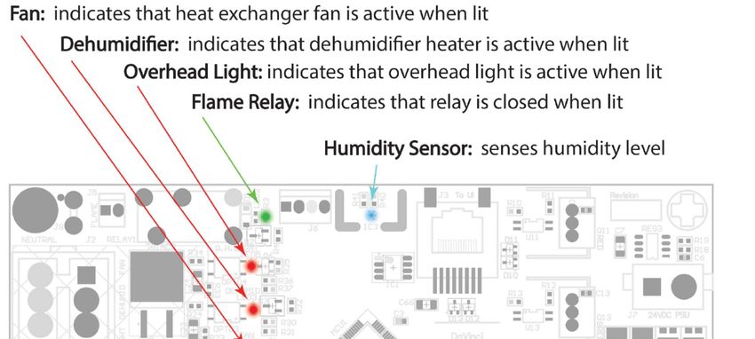
DaVinci Troubleshooting Guide
Page 6
Troubleshooting Steps
Is the GREEN “Ready Light” a. Is the main breaker on?
on?
b. Is the main power switch turned off?
XMF Fuse c. Is there a service switch on the main power line? Is it on?
d. Is the unit wired correctly? (Incoming power to power in, not power to
power vent)
Ready Light
e. Check the transformer fuse (labeled XMF) on the
PDB (see #1 on Diagram A, on page 18). Replace as needed (1 amp) f. Check
input power to the transformer- Line Voltage
g. Check output voltage from the transformer - 24 VAC
a. Can you hear the fan or feel the vacuum?
Does the Power Exhaust Fan (You will need someone at the Power Exhaust Fan to verify)
come on at initial power up or b. Check the incoming power (see above).
call for flame? c. Is ODAM light on? The fan may not initialize until resolved (see next
page).
d. Is the fan wired properly?
REO Fuse
FAN Fuse
e. Check fuses on PDB labeled “FAN” or “REO”. Replace as needed (6.3
amp SLO-BLO).
f. Check voltage to the Power Exhaust Fan - Should be Line voltage during
purge.
g. What color is the LED in the center of the PDB?
Green = Ready
Yellow/Orange = Call for Flame
Red = Fault
No light = No power or dead PDB, blown transformer fuse, or bad AC
transformer.
At initial power up or switch a. The pilot trying to light immediately upon powering up with or without the
“ON”, Does the PILOT start exhaust fan operation typically means that there is a short in the junction
sparking immediately? box.
b. Pinched wire, short, reversed wiring, etc.
c. The IFC is bad and will need to be replaced after the short is found.
17601900 - 6/9/21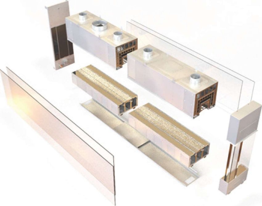
DaVinci Troubleshooting Guide
Page 7
a. Check fuses labeled ODAM & IDAM on the PDB (see diagram). These
fuses are in series so a problem in either the intake or exhaust damper
circuits could cause a fuse to blow. Replace as needed (1 Amp).
b. Verify the damper blade operation. Check for obstruction in the vent
blocking the damper blade.
c. Disconnect the square Molex connector from the interior side of the
electrical junction box. Check continuity between the RED and BLACK
wires to the exhaust damper. If no continuity either the exhaust damper is
closed, broken, damaged wiring, or the microswitch is bad. Jump the RED
and BLACK wires and try starting the fireplace. If the fireplace operates
properly the problem is outside the firebox. See the list of possible causes
below*.
*OTHER POSSIBLE CAUSES
RED and BLACK wires reversed
or shorted together, in the
exhaust damper wiring harness
causes the damper to open during
pre-purge of the initial power on.
At the end of the purge or end of
burn if a call for flame was
Is the ODAM light on the PDB initiated before the end of the pre-
RED? purge the damper will close and
This may keep the exhaust fan will not reopen unless power is
from operating at startup. removed. With the 10 sec. delay
the PDB, the damper will close
during the delay and will not
ODAM Fuse
reopen unless power is removed.
BROWN and BLACK wires
IDAM Fuse
reversed or shorted in the exhaust
damper wiring harness causes
ODAM Light the exhaust and/or intake damper
fuses to blow. If 6.3 amp fuses
are installed and the short still
exists, the fireplace will not
operate and the PDB may exhibit
all LED lights blinking or some
other random pattern.
ODAM fault - If fuses are
good, jump the RED and
BLACK wires in the
Exhaust Damper
harness. If the fault
continues check
intake/exhaust damper
fuses and replace them
as necessary. If the
fuses are
okay, disconnect the intake damper wires (even if there is no intake
damper in the system). If the fault goes away the problem is in the intake
damper wires.
Intermittent operation with 0-DAM Fault generally means a loose
connection in the junction box of the Exhaust Fan/Damper or a loose pin
in a Molex connection somewhere in the Exhaust Damper wiring harness
circuit.
17601900 - 6/9/21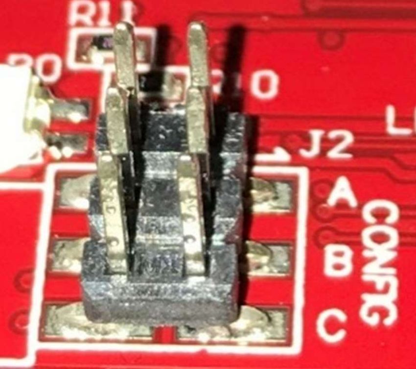
DaVinci Troubleshooting Guide
                                                                                                              Page 8
                                     a. Turn up the speed of the fan.
                                     b. Is the Power Exhaust Fan operating? Can you feel a vacuum in the
Is the APS LED light on the PDB         fireplace? Do you feel air blown into the firebox?
RED?                                 c. Check continuity of the APS switch.
                                     d. Check for cracked, kinked, or missing hose from APS to copper tubing.
                                     e. Check for blocked or damaged copper tubing in the flue.
                                     f. Did copper tubing get inserted into venting above “T” or Plenum (if
                                        applicable). Not into flue collar? Is copper tubing kinked?
             APS Light               g. Is the APS light on and is there is a green “ready state” light or red fault
                                        light or is just the red APS light on? The APS is sensing a draft when there
                                        is not supposed to be a draft. In other words, the fan is on when it should
                                        not be.
                                     h. Check continuity on the yellow and blue wires between the PDB and the
                                        APS. Replaces spades as needed.
                                     i. Check for 5 VDC - yellow and blue wires to APS and at PDB
                                     a. Are there lights on the PDB? (If not see the first section)
                                     b. Is the exhaust damper opening?
                                     c. Is the damper blade obstructed?
                                     d. Check fuses labeled ODAM and IDAM on the PDB (see #4 and #5 on
                                        diagram A on page 18). These fuses are in series and so a problem in
The intake damper does not              either the intake or exhaust damper circuits could cause a fuse to blow.
open.                                   Replace as needed (1 amp).
                                     e. Check voltage to the intake damper – 24 VAC. If the voltage is not correct,
                                        look for damage to the wires (for example a nail or staple through the
                                        harness).
                                     f. If the voltage is correct and the damper only opens with an assist, replace
                                        it.
                                     a. Is the Rheostat set at high?
                                     b. Check voltage to the Power Exhaust Fan?
Does the Power Exhaust Fan
never slow down at the end of            o Does it adjust up or down? If no, replace rheostat.
the startup purge?                       o Check PURPLE wire & ground – Line voltage
                                         o Check BLACK wire and ground – rheostat output
                                     c. Is intake duct sized right?
                                     a. Is the Rheostat turned off?
                                     b. Check fuses on PDB labeled REO and FAN (see #2 & #3 on Diagram A
Does the Power Exhaust Fan              page 18). (6.3 amp).
turn off 30/40 seconds after the     c. Check voltage from PDB to Rheostat. If no voltage then replace PDB.
call for flame?                         PURPLE wire & ground – Line voltage
                                     d. Check voltage to the Power Exhaust Fan? If no voltage then replace
                                        rheostat. BLACK wire and ground – rheostat output
                                     a. Wrong size fuse (probably the 6.3 amp) installed in the intake or exhaust
Do all the lights flash or are all      damper slot on the PDB.
the lights on the PDB?               b. Short in wiring to intake or exhaust damper or crossed wire in harness (see
                                        Other Possible Causes).
                                          If the transformer fuse continues to blow after being replaced there is
                                          probably a short in the exhaust damper or intake damper wiring.
Is the Transformer Fuse blown?            Disconnect both harnesses, replace the fuse, and then plug either one
                                          back in. If the fuse blows, the problem is in that circuit. If the fuse doesn’t
                                          blow, repeat with the other circuit.

                                                   17601900 - 6/9/21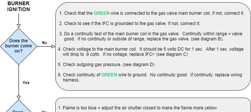
DaVinci Troubleshooting Guide
                                                                                                            Page 9
                                     a. PRE-TOUCHSMART - Check voltage at the on/off switch. 5VDC. If no
                                        voltage present the Over Heat snap disc has opened or failed.
                                        TOUCHSMART - Is the flame icon lit? If yes, check the AUX. board for a
                                        green light indicating a call for flame. Check the “Ready” light on the PDB.
                                        If the “Ready” light is GREEN and the “Flame Relay” light on the AUX.
Does the unit burn normally and         Board is lit, check continuity of the RED wire between the 2 boards. No
then suddenly shut down                 continuity = check the snap disc.
(typically after 2 hours or more),   b. Is there too much media on the burner and media trays? Is it the correct
or is the Glass Overheating?            media? Is it placed properly?
                                     c. Is the Intake Damper Open?
                                     d. Is the intake duct restricted or crushed?
                                     e. Is the exhaust restricted?
                                     f. Can you turn the rheostat up to increase the fan speed?
                                     a. Is there a green LED light on the LED power supply/ transformer? If no
                                        check incoming power to the unit and transformer.
                                     b. Check the voltage out of the transformer – black and white wire 24 VDC.
Do the LED lights work?              c. Check voltage at the wall switch? Heavier gauge Red and Black wires – 24
Slide Controls?                         VDC
                                     d. Check voltage from lighter gauge wire between BLACK and RED, BLUE,
                                        GREEN – 24 VDC
                                     e. Check individual Molex connections on LED strips.
                                     a. Is there a green LED light on the LED power supply/transformer? If no,
                                        check incoming power to the unit and transformer.
Do the LED lights work?              b. Check the voltage out of the transformer – GREEN and RED wire 24 VDC.
TouchSmart                           c. Are the Touch Pad and Aux Board communicating? Quick green
                                        communication Status Light (see page 24)
                                     d. Verify connections at Aux Board, Junction Box, and LED Strips.

If the unit sparks and there are no fault codes see the GreenSmart Troubleshooting steps
                                  on the following pages.

                                                 17601900 - 6/9/21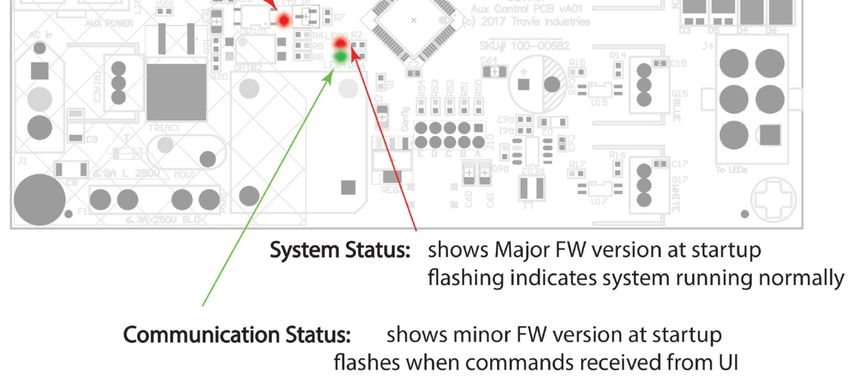
DaVinci Troubleshooting Guide
Page 10
TouchSmart
Notes: A RED flashing light on the Auxiliary Board and the back of the Wall Control or User Interface is a good thing.
This means that the two boards are operating properly.
All white LEDs that cannot be changed, indicate that the Auxiliary Board does not have power.
1. Check the fuse on the Auxiliary Board (6.3 Amp)
2. Verify power to the Auxiliary Board.
See page 19 for additional diagnostic lights.
Transient Voltage
Do all lights on the TouchSmart wall control blink and does the Ready light on PDB turn GREEN? Add
transient voltage suppressor (250-05407) to system
No Lights on TouchSmart Control
See above
Check CAT cable between wall control and Aux. Board.
Aux. Boards and TouchSmart Controllers must be compatible versions.
Auxiliary
Board
Firmware Versions Firmware Versions
1.0 to 1.3 (obsolete) 1.5 and Higher
Firmware Versions
TouchSmart
Not Compatible
Controller
1.0 to 2.2
Firmware Versions
2.3 or Higher
Not Compatible
Serial Number Range for Control Versions
Version Notes SN Range
Analog Use the switch and LED slider 3501-000000
TouchSmart V1a Controller “wakes up” when touched without changing settings (unless it is a long touch) 3501-001433
TouchSmart V1b Controller flashes when touched and will continue to flash during the startup cycle 3501-002989
17601900 - 9/1/21DaVinci Troubleshooting Guide
Page 11
GreenSmart Troubleshooting - Flow Chart
17601900 - 6/9/21DaVinci Troubleshooting Guide
Page 12
17601900 - 6/9/21DaVinci Troubleshooting Guide
Page 13
GreenSmart Troubleshooting Cont.
Continuity Testing Gas Valve
Disconnect wires for continuity test
340 +/- 15 Ω
Diagram B
Voltage Testing Gas Valve
A = Pilot Coil B = Burner Coil
5v
.9v 5 volts
for 1 sec.
Stabilizes
at about
0.9volts
B
A
A&B
Diagram C
Gas Pressure Testing Manifold Pressure
Test Port
Incoming
Diagram C Pressure Test
Port
17601900 - 6/9/21DaVinci Troubleshooting Guide
Page 14
SIT Base IFC
3.15A
F USE
Diagram E
17601900 - 6/9/21DaVinci Troubleshooting Guide
Page 15
DaVinci Parts
TouchSmart®
Service Kit 94400042
Master Power
On/Off Main 250-05502
Harness
SIT Base IFC 250-05257
Power
250-03402
Distribution Board
Valve, DaVinci NG 250-03400
Transformer 250-03403
17601900 - 6/9/21DaVinci Troubleshooting Guide
Page 16
Air Pressure Switch 250-03405
Maestro
(36x48, 36x58, and
48x48)
250-04275
Pilot Assembly 250-04275
Snap Disc 250-03415
Fuse 6.3 amp 250-03576
Fuse 1 amp 250-03982
LED control switch 250-03577
Decora Switch 250-00778
LP Regulator 250-00778
Natural Gas
250-04490
Regulator
17601900 - 6/9/21DaVinci Troubleshooting Guide
Page 17
Rheostat 250-03401
LED Power
250-04942
Supply/Transformer
Auxiliary Control
250-05158
Board
CUSTOM FIREPLACES TM CUSTOM FIREPLACES TM
White Heat H
O
U
H
O
U
Exchanger Wall 250-05154
R
S
R
S
Control
White Timer Wall 250-05156
Control
Lights Color Heat Lights Color Timer
CUSTOM FIREPLACES TM CUSTOM FIREPLACES TM
Black Heat H
O
U
H
O
U
Exchanger Wall 250-05155 R
S
R
S
Control
Black Timer Wall 250-05157
Control
Lights Color Heat Lights Color Timer
Transient Voltage
250-05407
Suppressor
17601900 - 6/9/21DaVinci Troubleshooting Guide
Page 18
Power Distribution Board
FUSES LED LIGHTS
XMF Transformer (1 amp) APS Air Pressure Switch
REO Rheostat (6.3 amp Slow Blow) ODAM Exhaust Damper
FAN Power Exhaust Fan (6.3 amp Slow Blow) FAN-OD Power Exhaust Fan/Exhaust Damper
ODAM Exhaust Damper (1 amp) FLAME Flame
GREEN = Ready
IDAM Intake Damper (1 amp) READY Red = Fault
Yellow/Orange = Call for Flame
Where to look for the cause of blown fuse(s)
Fuse Size Where to look
Aux. Board 6.3 amp Overhead lights Dehumidifier Heat Xchanger Main Power
Fan* 6.3 amp Wired Incorrectly Main Power Possibly Bad Fan
Rheostat* 6.3 amp Wired Incorrectly Main Power Possibly Bad Fan
Intake Damper** 1 amp Short in wiring Bad Motor Wires connected together
Exhaust
1 amp Short in wiring Bad Motor
Damper**
Short in wiring to
Bad AC
Transformer 1 amp intake or exhaust Bad Damper Motor
Transformer
damper
* Remember the Fan and Rheostat fuses are in series
** Remember the Intake and Exhaust Damper fuses are in series
17601900 - 6/9/21DaVinci Troubleshooting Guide
Page 19
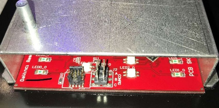
DaVinci Aux Power Board Indicators
PCB Rev A01 Doc Rev 101
17601900 - 6/9/21DaVinci Troubleshooting Guide
Page 20
User Interface Configuration
Configuration
With the UI face down, locate the configuration terminals as shown below.
The placement of jumpers on these terminals will change the function of the controls on the board.
Function Open Jumped Notes
A
Timer / Heat Exch Timer Heat Exchanger Jumper is factory installed.
B
Overhead Lights Overhead Lights No Lights May need to install/remove jumper.
C
Not Used
Examples:
This configuration is for a heat This configuration is for a timer with This configuration is for a timer with
exchanger with overhead lights no overhead lights. overhead lights.
A A A
B B B
C C C
There are 2 configurations – each with its own operating instructions
The DaVinci fireplace has gone through several configurations. Give this instruction sheet to the end-user and review
fireplace operation with the end-user to make sure they are familiar with all the features.
There are 2 Control Configurations
YES Is Jumper B NO
in Place?
Version 1 Control Overhead Light
Configuration Configuration
17601900 - 6/9/21DaVinci Troubleshooting Guide
Page 21
Wiring Diagram – Pre-TouchSmart
Caution: Label all wires prior to disconnection when servicing controls. Wiring errors can cause improper and dangerous
operation. Verify proper operation after servicing.
Warning: Do not disconnect or alter the air pressure switch wiring. This is a safety component that is critical to the safety of this
fireplace.
17601900 - 6/9/21DaVinci Troubleshooting Guide
Page 22
Wiring Diagram - TouchSmart® - Pre-Master Power Switch
Caution: Label all wires prior to disconnection when servicing controls. Wiring errors can cause improper and dangerous
operation. Verify proper operation after servicing.
Warning: Do not disconnect or alter the air pressure switch wiring. This is a safety component that is critical to the safety of this
fireplace.
17601900 - 6/9/21DaVinci Troubleshooting Guide
Page 23
Wiring Diagram - TouchSmart® - Power Switch
Caution: Label all wires prior to disconnection when servicing controls. Wiring errors can cause improper
and dangerous operation. Verify proper operation after servicing.
120 VAC
120 VAC Main Power
M Power In
Power In
Green
White
Switch
Black
120 VAC Power 3.15A
F USE
(several components
inside fireplace) Primary
Flame Spark
Rod Base
Detect Integrated
Fireplace
Control
(IFC)
Intake
Dampers
Black
Yellow / Green
Black
Power In
120 VAC
Air Category 2
Gray
White
24 Volt AC Pressure
Switch
Orange
Transformer 3.15A
F USE
Yellow
Green
B la ck
Whi te
Fuses* Secondary
Base
Brown
(see below) Blue
Yellow Integrated
Fireplace
Wh ite
Gr ee n
B la ck
Blue Blue
Blue F-OUT
Control (IFC)
Black
F-IN
Blue
Black
Power Dist. Board
Pu rple
Wh ite
Red
(Green Board)
* Fuse Layout
Exhaust Damper
(6.3 Amp.Sl.Bl.)
(6. 3 Amp.Sl.Bl.)
Power Exhaust
(1 Amp)
Ex. Rheostat
T ransformer
(1 Amp)
Fireplace Junction Box
Intake Damper
Bla ck
(1 Amp)
Re d
Bl ac k
Red
Blue
Wh ite
Black
Brown
Exhaust
Fireplace Junction Box
Exhaust Damper Exhaust Blower Damper Thermodisk
Wire Harness Junction Box
Capacitor Optional
120 VAC
Heat Exchanger Power In
Optional
De-Humidifier
24 Volt DC
CUSTOM FIREPLACES TM
Gre en
Optional
Bla ck Bla ck
Transformer Blu e H
Bla ck Overhead Lights Red Pin k
O
U
R
S
Bla ck Black
Wh ite
Gre e n
Wh ite
Gre e n
Auxiliary Board
LED
Power (Red Board) Light Lights Color Tim er
Exhaust Blower Exhaust 120 VAC Strips Touch
Junction Box Power In
Screen
17601900 - 6/9/21DaVinci Troubleshooting Guide
Page 24
LED Wiring Diagram – Pre-TouchSmart
17601900 - 6/9/21DaVinci Troubleshooting Guide
Page 25
NOTES
17601900 - 6/9/21DaVinci Troubleshooting Guide
Page 26
NOTES
17601900 - 6/9/21You can also read