UC Berkeley Indoor Environmental Quality (IEQ) - eScholarship
←
→
Page content transcription
If your browser does not render page correctly, please read the page content below

UC Berkeley
Indoor Environmental Quality (IEQ)

Title
Ceiling Fan Design Guide

Permalink
https://escholarship.org/uc/item/6s44510d

Authors
Raftery, Paul
Douglass-Jaimes, David

Publication Date
2020-03-01

License
https://creativecommons.org/licenses/by-nc-sa/4.0/ 4.0

 eScholarship.org Powered by the California Digital Library
 University of California
Ceiling Fan Design Guide
 Paul Raftery and David Douglass-Jaimes
 First Edition Released March, 2020
Created with funding from the California Energy Commission’s
 Electric Program Investment Charge Program (EPC-16-013)
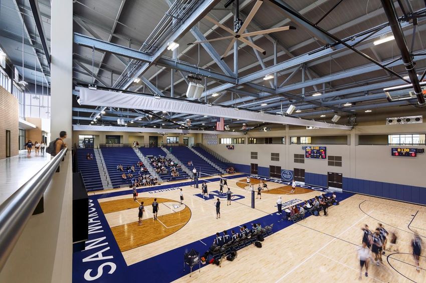
Table of Contents
ABOUT THIS DESIGN GUIDE........................................................................................................................... 4
 Benefits Of Ceiling Fans ............................................................................................................................. 5
CEILING FANS AND THERMAL COMFORT .................................................................................................... 10
 Human Body Thermoregulation .............................................................................................................. 10
 Factors of Thermal Comfort .................................................................................................................... 11
 How Ceiling Fans Help Meet Thermal Comfort Goals ............................................................................. 12
 ASHRAE Standard 55 Thermal Environmental Conditions For Human Occupancy .................................. 12
 Thermal Comfort Calculations With Elevated Air Speed ......................................................................... 13
 CBE Thermal Comfort Tool ...................................................................................................................... 14
 Ceiling Fans For Destratification In Heating Mode .................................................................................. 15
ABOUT CEILING FANS .................................................................................................................................. 17
 Fan Types ................................................................................................................................................ 17
 Blade Types And Configuration ............................................................................................................... 19
 Motor And Drive Types ........................................................................................................................... 21
FAN SELECTION, SIZING, AND LAYOUT ........................................................................................................ 22
 Understanding Fan Metrics ..................................................................................................................... 22
 Uniformity Of Air Speeds ......................................................................................................................... 30
 Selecting Fan Sizes And Determining The Layout .................................................................................... 33
 Fan Mounting Height And Clearances ..................................................................................................... 35
 Lighting .................................................................................................................................................... 37
CONTROLS ................................................................................................................................................... 41
 User Interface .......................................................................................................................................... 41
 Types Of Control Automation .................................................................................................................. 43
 Additional Considerations For Choosing A Control Type ......................................................................... 43
 Integration With Building Controls And Sequences Of Operation ........................................................... 44
 Airflow Direction ..................................................................................................................................... 45
Occupant Interface and Education .............................................................................................................. 47
Applications ................................................................................................................................................. 49
CODES AND STANDARDS ............................................................................................................................. 54
 Fire Code Requirements .......................................................................................................................... 54
 Seismic Requirements ............................................................................................................................. 55

Ceiling Fan Design Guide 2020 Page 2

Energy Code Considerations.................................................................................................................... 56
 ASHRAE 216 And Fan Testing Procedures ............................................................................................... 57
Costs ............................................................................................................................................................ 58
Modeling, Simulation and Energy Savings Estimation ................................................................................. 59
CBE Ceiling Fan Design Tool ........................................................................................................................ 61
Acknowledgements ..................................................................................................................................... 64
APPENDIX: DESIGN, SPECIFICATION, AND INSTALLATION CHECKLIST ......................................................... 65
APPENDIX: CASE STUDIES ............................................................................................................................ 67
APPENDIX: ADDITIONAL RESOURCES AND REFERENCES ............................................................................. 67

Ceiling Fan Design Guide 2020 Page 3
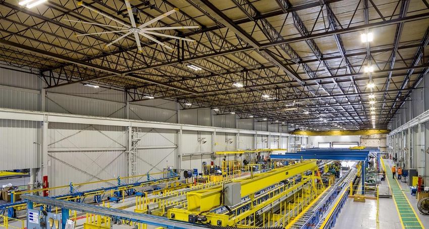
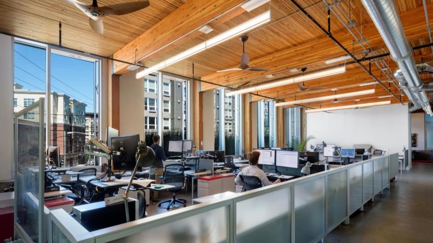
Figure 1: Bullitt Center, Seattle, WA, 2013. (Architecture:: Miller Hull, MEP: PAE Engineers,
 Photo: copyright Tim Griffith)

ABOUT THIS DESIGN GUIDE
This guide enables architects, designers, and engineers to maximize the many benefits of integrating
ceiling fans into building systems. It introduces the advantages of using ceiling fans, describes how ceiling
fans work, provides guidance and resources for designing spaces with ceiling fans and specifying ceiling
fan products.

 Figure 2: Highlights of the design guide include thermal comfort benefits of ceiling fans, guidance for control and user interface
 strategies, a ceiling fan design and specification checklist, and an introduction to the CBE Ceiling Fan Design Tool

Ceiling Fan Design Guide 2020 Page 4

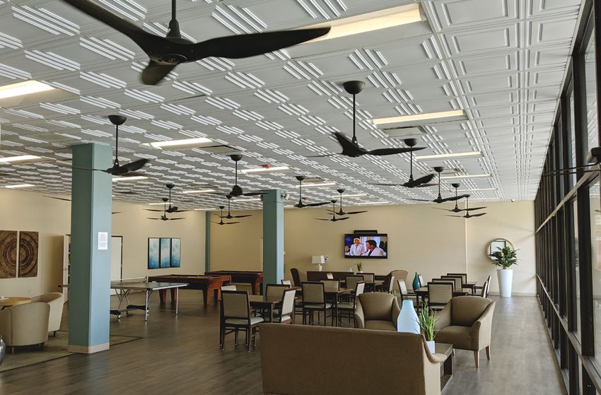
Benefits Of Ceiling Fans
Ceiling fans are more than just a basic amenity for residential applications. Increasingly, ceiling fans are
found in applications varying from industrial and warehouse applications to offices and high-end
hospitality settings, and everything in between.
The extensive use of ceiling fans in residential applications (over 80% of single family homes in the United
States have at least one ceiling fan), as demonstrated in Figure 3 below, indicates their effectiveness in
supporting thermal comfort, and occupant demand for controllable air movement.

 Figure 3: Number of fans per household by housing unit type, data source: U.S. Energy Information Administration 2015
 Residential Energy Consumption Survey

This widespread applicability stems from the many benefits that ceiling fans can provide in interior
environments.
The key benefits of ceiling fans are as follows:
 • Thermal Comfort
 • Improved Air Distribution
 • Improved Perceived Air Quality
 • HVAC First Cost Savings
 • Energy Savings
The following subsections describe each of these benefits in more detail.

Thermal Comfort
Simply stated, thermal comfort is an occupant’s satisfaction (“comfort”) with the perceived temperature
(“thermal sensation”) of their environment. For centuries, humans have been using fans to help regulate

Ceiling Fan Design Guide 2020 Page 5

thermal comfort. The reason for this is simple: in warm conditions there is generally less heat lost from
the skin than in cooler conditions, and so people are at risk of warming up (the science of thermal
comfort is described in more detail below). Increased air movement across the skin carries away more
heat from the body (via convection and evaporation), and thereby restores comfort. Since the advent of
mechanical HVAC systems, building designers have largely focused on a single factor of thermal comfort:
air temperature. However, modifying other factors of thermal comfort, such as air speed, changes how a
particular air temperature is perceived. Occupants near a ceiling fan will feel cooler than they would at
the same temperature in still air, similar to the phenomenon of “wind chill”, though the wind chill index is
typically used for higher air speeds and colder temperatures than occur indoors. Similarly, when the air
temperature is warmer, occupants near a fan will feel more comfortable than they would in still air
conditions.

Improved Air Distribution
In addition to the thermal comfort benefits of increased air speeds, ceiling fans can also improve air
distribution, working in concert with the HVAC system to provide the desired thermal conditions more
consistently throughout a space. When correctly designed and operated, ceiling fans support the HVAC
system to minimize temperature gradients within a space, providing more consistent temperature and air
quality conditions throughout a space. This improved air distribution can be effective for both heating
and cooling scenarios. For example, ASHRAE Standard 62.1 – Ventilation for Acceptable Indoor Air Quality
lists a ventilation effectiveness of 0.8 for ceiling-supplied warm air systems (due to stratification of the
warm air near the ceiling), but adding ceiling fans in this scenario brings the ventilation effectiveness back
to 1.0, or fully mixed condition, reducing the amount of outside air required.

Improved Air Quality
By increasing air movement and improving air distribution in a space, ceiling fans also improve air quality.
The increased air movement prevents the sensation of stale or stuffy air, and can help dissipate odors.
One recent study has also documented a measurable air quality improvement from ceiling fans by
dissipating CO2 and other exhaled pollutants that would otherwise gather near occupants in still air
conditions. Large-scale studies of occupant survey data indicate that occupants would prefer more air
movement than they have, especially in conditions where occupants report feeling warm, as illustrated in
Figure 4.

Ceiling Fan Design Guide 2020 Page 6

Figure 4: Occupant preference for more air movement (Data source: ASHRAE Global Thermal Comfort Database II)

First Cost Savings
The benefits described above—thermal comfort, improved air distribution, and improved air quality—
achieve more than just increased occupant satisfaction, they can also help reduce first costs for HVAC
systems. Using ceiling fans to more effectively distribute air throughout a space can reduce the extent of
distribution ductwork and diffusers required to serve a zone. Additionally, if the same zone is designed to
a slightly higher cooling setpoint due to the comfort cooling effect provided by the fans, this can also
reduce the required latent and sensible cooling capacity of the HVAC system, providing first cost savings
to equipment and ductwork.

Energy Savings
Perhaps most importantly, when implemented effectively as an integral component of a building’s
thermal comfort strategy, ceiling fans can also result in significant energy savings by reducing the demand
on the HVAC system. Although ceiling fans consume energy, the potential HVAC savings outweighs fan
energy use, typically by a factor ranging between 10 and 100 times. The primary energy saving derives
from thermal comfort benefits of ceiling fans, keeping occupants comfortable at higher temperatures and
allowing for increased cooling setpoints. Effectively, a room with ceiling fans is thermally comfortable
over a wider range of temperatures than a room without ceiling fans. This wider range of temperatures
reduces the cooling and fan energy consumption of the HVAC system. Counterintuitively, this wider range
of temperatures also reduces heating energy consumption because when a space is warmer, it will take
longer to cool down to the heating setpoint. Lastly, when ceiling fans are used to provide air distribution,

Ceiling Fan Design Guide 2020 Page 7

reducing the extent of distribution ductwork and diffusers, they also help reduce HVAC fan energy by
reducing the pressure drop in the air system. The section on Modelling, Simulation and Estimating Energy
Savings discusses these effects in more.

History
Methods of increasing air speeds to produce a cooling effect have been in use for centuries, from the
most rudimentary handheld fans to more elaborate systems of sail-like fabric sheets or wooden panels
mounted to ceilings. Ceiling-mounted “punkah” fans, like those shown in Figure 5, were common in
places like colonial India and the Antebellum South in the US, and were manually operated with ropes
pulled by servants or enslaved people. For a more localized cooling effect, there were also fan chairs like
the one used by George Washington, as shown in Figure 5.

 Figure 5: Historical fan technologies: fabric punkah fans at the Church of St. Francis in Kochi, India, circa 1795 (photo by Adam
Jones via Wikimedia Commons, creative commons license CC BY-SA 3.0), and a carved wood punkah fan at Melrose Plantation in
 Natchez, Mississippi, circa 1847 (photo courtesy The Punka Project); George Washington’s fan chair, circa 1790 (photo courtesy
The Punka Project); ceiling fans on a New York City subway car, circa 1910, at the New York Transit Museum (photo by Eric Fisher
 via Wikimedia Commons, creative commons license CC BY 2.0).

Ceiling Fan Design Guide 2020 Page 8
The first electric ceiling fan was invented by Philip Diehl in 1882, and the new technology quickly gained in
popularity. In the 1910s ceiling fans were even installed on New York City subway trains. However, with
the advent of mechanical cooling, and a concerted marketing effort to present air conditioners as the sole
modern, healthy means of providing comfort cooling, ceiling fans waned in popularity and largely
disappeared from many types of indoor spaces.
However, the inherent effectiveness of ceiling fans at cooling with air movement did not change, and
today designers and engineers are increasingly recognizing the synergy of combining modern ceiling fans
with mechanical HVAC systems to improve comfort and energy efficiency in a broad range of applications.
Ceiling fans should no longer be seen simply as a decorative element or residential amenity, but rather as
an integral part of an effective thermal comfort system.

Ceiling Fan Design Guide 2020 Page 9
CEILING FANS AND THERMAL COMFORT
In this section we discuss the thermal comfort related effects of increased air movement using ceiling
fans for cooling applications. We also discuss tools such as the CBE Thermal Comfort Tool to help
determine the right air speed and other factors for optimal thermal comfort. Figure 6 shows the cooling
effect–or how many degrees warmer the air temperature can be to provide the same level of thermal
comfort–associated with increased air speeds. This figure also highlights that the design air speeds under
discussion in this guide are well below the air speeds that a person experiences every day. An example
design speed of 0.5 m/s or 100 fpm, equal to approximately 2 °C or 4 °F cooling effect, is approximately
half the air speed that a person experiences just from the relative motion of walking slowly through still-
air conditions.

 Figure 6: Cooling effect of increased air speed1

Human Body Thermoregulation
As discussed above, thermal comfort is an occupant’s satisfaction (“comfort”) with the perceived
temperature (“thermal”) of their environment. This satisfaction depends on how much heat is released or
retained by the occupant’s body. Heat transfer to and from the body occurs in four ways. These are listed
in order of decreasing amount of heat transfer under standard conditions:
 • Radiation - heat transfer via electromagnetic waves between objects that are not touching. The
 most familiar form of radiant heat transfer is the radiant energy from the sun. However,

1
 for a ‘typical’ office worker in cooling conditions, according to ASHRAE 55:2017 at an operative temperature of
76F, 50% relative humidity, 0.6 clo, 1.13 met.

Ceiling Fan Design Guide 2020 Page 10
longwave radiation to surrounding surfaces is also a primary mechanism of heat loss from the
 human body.
 • Convection – heat transfer between a solid source and a fluid, in this case between skin and air, is
 of similar magnitude to heat transfer by radiation under standard conditions (still air). The
 amount of heat loss from the body through convection depends on the air speed, as that directly
 affects the convective heat transfer rate from the skin. Still air acts like an insulator, with
 convection only occurring due to the buoyancy driven effect driven by the temperature
 difference between skin (or clothes) and the surrounding air. As air speed increases, this gives
 rise to forced convection, allowing for more heat to be released.
 • Evaporation - heat loss through the phase change of sweat from liquid to vapor. The phase
 change requires energy in the form of heat extracted from the skin, cooling the body when sweat
 evaporates. The rate of evaporation depends on the humidity of the surrounding air, with drier
 air able to absorb more moisture through evaporation.
 • Conduction - heat transfer between objects in contact. The cooling sensation of holding a cold
 drink or the warming sensation of touching a hot surface are both examples of heat transfer
 through conduction. Conduction is typically responsible for the smallest share of heat loss from
 the body.

 Figure 7: Human body heat rejection

Factors of Thermal Comfort
ASHRAE Standard 55 – Thermal Environmental Conditions for Human Occupancy identifies six factors that
affect thermal comfort:
 • Metabolic Rate - the rate of transformation of chemical energy into heat and mechanical work,
 based on the level of activity. For example, the body generates more heat while walking than
 while sitting still.
 • Clothing Insulation - the insulating effect of clothing preventing heat loss from the body. For
 example, shorts and a short-sleeve shirt will allow more heat loss from the body than pants and a
 heavy sweater.
Ceiling Fan Design Guide 2020 Page 11
• Air Temperature - the temperature of air at a certain point.
 • Mean Radiant Temperature - the average temperature of the surfaces surrounding a certain
 point, weighted by how large an angle that surface makes when viewed from that point.
 • Air velocity or speed - the velocity or speed of air at a certain point.
 • Humidity - how much moisture the air contains.

How Ceiling Fans Help Meet Thermal Comfort Goals
Ceiling fans increase air speed, and increased air speed accelerates two of the heat transfer mechanisms
described above: convection and evaporation. Thus, ceiling fans accelerate heat loss from the body,
providing a cooling sensation. The cooling sensation from increased air speed allows the body to maintain
thermal comfort at higher air temperatures than what would be comfortable in still air.
In addition to providing comfort at increased temperatures, ceiling fans are capable of providing
instantaneous comfort effects that thermostat adjustments cannot. A thermostat and HVAC system that
conditions the whole room generally takes 15 minutes or longer before the occupant will perceive a
change in their thermal environment. However, a ceiling fan has an almost instantaneous effect. If an
occupant feels too warm, turning on or increasing the speed of a ceiling fan instantly provides a cooling
sensation. Similarly, if an occupant is too cool and the fan is operating, reducing the ceiling fan speed or
turning it off instantly provides a warmer sensation. Ceiling fans are also ideally suited to providing
adaptive or transitional comfort for changing human comfort conditions. Adjusting ceiling fan speeds can
help accommodate the natural fluctuations in body temperature and comfort preferences throughout
the day. Similarly, the adjustable nature of ceiling fans can provide enhanced thermal comfort during
transitional moments, such as the changing comfort needs when transitioning from an active metabolic
rate event (for example, after walking from a meeting in a different part of the building, or arriving in to
work from a morning commute) to a resting metabolic rate (such as sitting at a desk in an office), or
simply due to different personal thermal comfort requirements of occupants in the same physical space.
In order to determine how much air movement is needed for thermal comfort and occupant satisfaction,
we can look at ASHRAE Standard 55 and the CBE Thermal Comfort Tool.

ASHRAE Standard 55 Thermal Environmental Conditions For Human Occupancy
ASHRAE Standard 55 – Thermal Environmental Conditions for Human Occupancy identifies factors
(discussed above) that may affect thermal comfort in an indoor environment and how occupant
satisfaction is affected when these factors are changed. The standard also provides methods to
determine optimal values for each of the factors to create a comfortable environment.
Standard 55 outlines both a graphical and analytical method to determine acceptable thermal comfort
zones. In the graphical comfort zone method (Section 5.3.1 of the standard), comfort zones are shown on
a graph based on occupant metabolic rates and clothing insulation levels. By using space conditions, such
as temperature and humidity, it can be determined whether the space falls within the occupants’ comfort
zone. This method can only be used however when the occupants’ metabolic rates and clothing insulation
levels are within a certain range and does not account for changes in comfort zone due to elevated air
speed.

Ceiling Fan Design Guide 2020 Page 12
The analytical comfort zone method (Normative Appendix B) can be used for a wider range of occupant
characteristics. The analytical comfort method calculates a predicted mean vote (PMV) based on a
combination of thermal comfort factors. PMV is an index that predicts the average vote of thermal
sensation in a large group of people on scale from –3 (cold) to 3 (hot), where a score of 0 would be
considered perfectly comfortable. Using this method, a PMV between –0.5 and 0.5 must be obtained to
be ASHRAE 55 compliant.
ASHRAE 55-2017 Addendum C introduces comfort control classification levels (CCCLs) into the standard,
where a lower CCCL number indicates an improved level of occupant comfort. This captures the
beneficial effects of increased opportunities for local and group level control of thermal comfort.
 Table 1: ASHRAE 55-2017 Addendum C comfort control classification levels (CCCLs)

 CCCL Required Control Measure(s) Informative Examples Meeting CCCL
 1 Personal control of two or • Private office with a ceiling fan and an occupant
 more adjustable thermostat
 • Shared office with desktop fans and seat warmers for
 each occupant
 2 Personal control of one • Private office with an occupant adjustable thermostat
 • Shared office with a desktop fan for each occupant
 3 Multi occupant control of two • Shared office with an occupant adjustable thermostat
 or more and ceiling fan control

 4 Multi occupant control of one • Shared office with an occupant adjustable thermostat

 5 No occupant control • Shared or private office with an un-adjustable
 thermostat or no thermostat

Thermal Comfort Calculations With Elevated Air Speed
Standard 55 also provides a method called The Elevated Air Speed Comfort (Section 5.3.3. of standard) to
calculate thermal comfort in situations of elevated airspeed. This method uses a combination of the
Analytical Comfort Zone Method combined with the Standard Effective Temperature (SET) method
(Normative Appendix D of standard). Since increasing air speeds has a cooling effect, the method
calculates adjusted air and radiant temperatures according to how occupants are expected to feel under
increased air speed conditions to calculate a new PMV value. The “Standard Effective Temperature” (SET)
output translates the 6 thermal comfort factors (from above) into a single temperature equivalent. The
SET provides a single metric that can be compared across a variety of comfort conditions.
Cooling effect is also used to calculate the Cooling Fan Efficiency (CFE). CFE is defined in ASHRAE Standard
216, currently under development, as the ratio of the cooling effect to the input power of the fan. CFE
gives people a standardized way to compare how much cooling a fan provides when consuming the same
amount of energy.

Ceiling Fan Design Guide 2020 Page 13
CBE Thermal Comfort Tool
A helpful tool to find comfort zones at elevated air speeds according to ASHRAE 55 methodology is the
CBE Thermal Comfort Tool, an online tool developed by The Center for the Built Environment at the
University of California at Berkeley.
The user enters temperature, air speed, humidity, metabolic rate and clothing level into the tool to
calculate results including PMV, SET, and ASHRAE 55 compliance as well as generating the graph below in
Figure 8. The blue shaded area represents the ASHRAE 55 compliant comfort zone while the red mark
shows where the user inputs are relative to the comfort zone. The tool also supports the international
comfort standard ISO EN 16798.

 Figure 8: Example screenshot of the CBE Thermal Comfort Tool, showing user inputs, psychometric chart, and results

The CBE Thermal Comfort Tool also takes into account elevated air speeds. As the air speeds increase, the
range of acceptable temperatures increases, and the blue shaded area shifts to the right. Using higher air
speeds allows the user to be ASHRAE 55 compliant at higher cooling temperature setpoints. Note that
Standard 55 has a maximum average air speed permitted in the case that occupants do not have control
over the system (0.8 m/s or 160 fpm). This can be specified as an input in the Thermal Comfort Tool as
well. To support this functionality, users can also select the “air speed vs. operative air temperature”
mode from the drop down menu above the chart to view the comfort range and results in terms of air
speed and temperature, as shown in Figure 9, below.

Ceiling Fan Design Guide 2020 Page 14
Figure 9: Example screenshot of the CBE Thermal Comfort Tool showing air speed vs. operative air temperature mode

Ceiling Fans For Destratification In Heating Mode
In addition to directly cooling occupants, ceiling fans also effectively mix the air in a space, which has
several applications. The most common of these applications is where the temperatures in a space are
stratified, with much warmer air close to the ceiling and cooler air near the floor. This typically occurs in
spaces with high ceilings or where the heating equipment has a relatively high discharge temperature. In
these conditions, ceiling fans can mix the air in the space such that the temperature at the floor (and
close where the thermostat is located) is close to the average temperature in the space. This can save
energy and also improve occupant comfort. Ceiling fans can run in either direction to achieve this mixing,
though they will use more power to achieve the same mixing effect when operating in reverse (moving air
upward) than forwards (moving air downward). Note that when destratifying, the space is typically
operating in heating mode and operating at the lower end of the range of temperatures that define the
thermal comfort zone. As such it is very important to maintain very low air speeds in the occupied zone in
order to avoid the sensation of draft. Depending on the specific conditions, the occupant locations, and
the minimum speed capabilities of the fan, running the fan in forward or reverse may be better able to
achieve this goal.

Ceiling Fan Design Guide 2020 Page 15
Figure 10: Ceiling fans for destratification

Ceiling Fan Design Guide 2020 Page 16
Figure 11: Large-diameter ceiling fans at Barrie North School library. (Photo copyright Big Ass Fans)

ABOUT CEILING FANS
The following sections describe the different types of ceiling fans, and the features that differentiate
ceiling fan models.

Fan Types
As part of the “Uniform Test Method for Measuring the Energy Consumption of Ceiling Fans”2 the US
Department of Energy (DOE) defines a variety of ceiling fans types. For the purpose of this guide,
discussions focus on two main ceiling fan types:
 • Standard ceiling fan – any ceiling fan with a diameter greater than 18 inches but no more than 7 feet, and
 with the lowest point of the fan blades more than 10 inches below the ceiling. A standard ceiling fan not
 exceed the limits outlined in Table 2 below.
 • Large-diameter ceiling fan – any ceiling fan that is greater than seven feet in diameter. These are often also
 known as High Volume Low Speed (HVLS) fans.
In addition to these two primary types of ceiling fans, the DOE defines several other fan types that are
commonly used, many of which fall under the category of small-diameter ceiling fan.
 • Small-diameter ceiling fan – any ceiling fan that is more than 18 inches in diameter but less than or equal to
 seven feet in diameter, and with an airflow of at least 1,840 CFM and a rotational speed of more than 90
 RPM at its highest speed.
 o High-speed small-diameter ceiling fan – any small-diameter ceiling fan that has a blade thickness
 of less than 3.2 mm at the edge or a maximum tip speed greater than the applicable limit specified
 in Table 2 below.

2
 Appendix U to Subpart B of Part 430 – Uniform Test Method for Measuring the Energy Consumption of Ceiling
Fans, Code of Federal Regulations, Title 10, Chapter II, Subchapter D. https://www.ecfr.gov/cgi-
bin/retrieveECFR?gp=&SID=723eddbb09c4b806e38bab695a9f2dbd&mc=true&n=pt10.3.430&r=PART&ty=HTML#ap
10.3.430_127.u

Ceiling Fan Design Guide 2020 Page 17
o Low-speed small-diameter ceiling fan – any small-diameter ceiling fan that has a blade thickness
 greater than or equal to 3.2 mm at the edge and a maximum tip speed less than or equal to the
 applicable limit specified in Table 2 below. (“Standard ceiling fans”, defined above, are a type of
 low-speed small-diameter ceiling fan.)
 ▪ Hugger ceiling fan – any low-speed small-diameter ceiling fan for which the lowest point
 on the fan blades is less than or equal to 10 inches from the ceiling.
 • Very-small-diameter ceiling fan – any ceiling fan with one or more fan heads, each of which has a blade
 span of 18 inches or less, and with an airflow of at least 1,840 CFM and a rotational speed of more than 90
 RPM at its highest speed.
 • Highly-decorative ceiling fan – any ceiling fan with a maximum rotational speed of 90 RPM and less than
 1,840 CFM airflow at high speed.
Note that while these DOE definitions include a variety of subcategories for small-diameter fans, any fan
larger than seven feet in diameter is simply a “large-diameter” fan, with no further differentiation.
 Table 2: Ceiling Fan Blade and Tip Speed Criteria (Adapted from DOE Definitions)

 Thickness (t) of edges of blades Tip speed threshold
 Airflow Direction
 mm (inch) m/s (feet per minute)
 Downward-Only 4.8 > t ≥ 3.2 (3/16 > t ≥ 1/8) 16.3 (3200)
 Downward-Only t ≥ 4.8 (t ≥ 3/16) 20.3 (4000)
 Reversible 4.8 > t ≥ 3.2 (3/16 > t ≥ 1/8) 12.2 (2400)
 Reversible t ≥ 4.8 (t ≥ 3/16) 16.3 (3200)

As noted above, this guide is primarily focused on two main fan types, defined above as standard ceiling
fans and large-diameter ceiling fans. However, much of the discussion in this guide will also be relevant
to the other small-diameter ceiling fan types beyond the “standard” definition, and there is significant
overlap between many of the small-diameter ceiling fan subcategories. Note, for example, that “standard
ceiling fans” are a type of low-speed small-diameter ceiling fan, and “hugger ceiling fans” are essentially
equivalent to standard ceiling fans but with fan blades mounted closer to the ceiling (despite the negative
effect on efficiency) for suitability in spaces with lower ceiling heights.
In general, a larger diameter fan blade can move a larger volume of air than a smaller diameter fan blade.
As fan diameter increases, rotational speed is typically limited to prevent excessive noise from the fan
blades, especially near the blade tip. Additionally, where fans can be mounted at blade heights below 10
ft (i.e. almost all standard fans), rotational speed must be limited to meet safety criteria (see UL 507) for
the maximum speed of the blade tips. Large-diameter ceiling fans are sometimes referred to as “high
volume low speed” or HVLS fans. Because the design and shape of the fan blades can also have a
significant impact on airflow, as described in more detail below, the HVLS terminology is typically used to
describe large ceiling fans that are designed to prioritize performance in large commercial and industrial
spaces. For example, some large-diameter ceiling fans include “winglets” or blade tip fences (see
examples in Figure 11: Large-diameter ceiling fans at Barrie North School library. (Photo copyright Big Ass
Fans), Figure 38: High School Gymnasium, San Marcos, CA (Architecture: LPA Architect, Photo: copyright

Ceiling Fan Design Guide 2020 Page 18
Cris Costea), and Figure 40: Bluescope Buildings, North Carolina, USA (Photo: copyright Big Ass Fans)) to
maximize airflow and minimize noise, which is a less common problem in standard fans as the blade tip
speed is already constrained for safety reasons.
Though standard ceiling fans are often thought of in their residential applications, they are equally
effective for comfort cooling in most nonresidential applications (including offices, classrooms, gyms,
hospitality, etc.) where they can be positioned near the occupants. Large-diameter ceiling fans require
higher ceilings (typically at least 11 ft) and larger spaces free from obstructions to accommodate their
increased diameter. As a result, large-diameter ceiling fans are most often found in nonresidential
commercial and industrial applications.
Although the fan type definitions from the DOE are focused on fan diameter, in the case of specific fan
products there is some overlap in terms of applications and fan styles. Some large-diameter fans are
available in styles that are more frequently associated with standard fans, and some manufacturers have
HVLS fan models in diameters less than seven feet. Additionally, there are some large-diameter fans that
have a relatively low maximum rotational speed and thus, meet blade tip speed and thickness
requirements for mounting below 10 ft, though these also have a relatively low maximum airflow.
The DOE also defines a variety of other specialty ceiling fan types (including belt-driven ceiling fans,
centrifugal ceiling fans, multi-head ceiling fans, and oscillating ceiling fans), but those specialty types are
not the subject of this guide.

Blade Types And Configuration
Blade shape, number of blades, and blade pitch are important factors in increasing energy efficiency
while maximizing air flow through the fan blades.
There are two main types of blades shapes shown in Figure 12 below. Blade shapes have evolved over
time from flat to airfoil-style blades to become more energy efficient and maximize air movement. As the
name implies, flat ceiling fan blades are flat panels mounted at a fixed angle, whereas airfoil blades are
similar to airplane wings in section. Similar to the cross-section of an aircraft wing, the curvature of the
airfoil blades helps increase air flow through the ceiling fan, minimizing air turbulence at the trailing edge
of the blade common to flat blades. Airfoil-style blades are thus typically more efficient and also quieter
than flat blades. However, flat blades are cheaper to manufacture. Note that flat blades will perform
equally whether the fan is operating in the forwards (blowing down) or reverse (blowing upwards)
direction. In contrast, airfoil blades will not operate as efficiently in reverse, and will typically have a lower
airflow when doing so. Some fan models have blades that can be manually attached in inverted position,
or can mechanically invert the blade while it is attached to the fan, which allows for improved efficiency
when operating in reverse.

Ceiling Fan Design Guide 2020 Page 19
Figure 12: Ceiling Fan Blade Types

The number of blades is an important factor in increasing airflow of ceiling fans. Although increasing the
number of blades will increase airflow, the increased weight and drag due to the blades can cause a loss
in energy efficiency. Standard fans typically have between 3 and 5 blades, though some models have as
few as 2 blades or up to 6 blades. Large-diameter fans typically have 6 or 8 blades, though some models
have as few as 3 blades.
Similarly, increasing the blade’s angle may also increase airflow at the cost of energy efficiency. Academic
modeling studies have found the optimal blade angle to be 8-10° for residential fans. Manufacturers
recommend 12-15°. Some airfoil-style blades also vary the blade angle over the length of the fan blade,

Ceiling Fan Design Guide 2020 Page 20
with steeper angles toward the center of the fan to maximize air flow for the low blade speed in this
region, and reducing to shallower angles toward the tips where the blade speed is high in order to limit
drag and maximize energy efficiency.

Motor And Drive Types
There are three main types of motors used in ceiling fans: AC Induction, Permanent Magnet DC (PMDC),
and Brushless Direct Current (DC) motors. Generally, there are very large percentage efficiency savings
from moving from AC to DC motors for small fans, and far less of an effect for large diameter fans.
 • AC Induction:
 o How it works: Electromagnets on outside of motors (stator) creates a rotating magnetic field
 causing motor rotation through induction.
 o Benefits: Provides constant, even airflow and are cheaper than DC motors.
 • PMDC:
 o How it works: Permanent magnets are located on the motor stator creating a stationary magnetic
 field. A segmented commutator rotates within the magnetic field creating a mechanical switching
 of current direction.
 o Benefits: More energy efficient than AC motors and provides constant force over a wider range of
 speeds than AC motors.
 • Brushless DC:
 o How it works: Permanent magnets are rotated in motor creating a rotating magnetic field. Current
 direction in the stator is switched in relation to the magnetic field to create rotation.
 o Benefits: Most energy efficient of the three motor types (for small motors on small diameter fans,
 a DC motor often will use 70% less energy than an AC motor), most quiet, and has a longer service
 life than PMDC motors.
Fans may also be either direct drive or gear-driven. Almost all small-diameter fans are direct drive, but
large-diameter ceiling fans may either be direct-drive or gear-driven.
Direct-drive fans are quieter than gear-driven fans, have a more refined appearance and have reduced
operating cost. However, direct-drive fans do provide less air flow and it may be harder to replace the
motors. Due to this, direct-drive fans are typically used in situations where sound level and aesthetics are
a concern and less airflow is needed.
On the other hand, gear-driven fans allow for higher motor power and are often used in situations where
maximizing airflow is a priority over sound levels or aesthetics. This is well suited for industrial settings
where ceilings are high and there is little or no air conditioning.

Ceiling Fan Design Guide 2020 Page 21
Figure 13: Coastal Biology Building, University of California Santa Cruz. (Architecture: EHDD,
 Photo: copyright Michael David Rose)

FAN SELECTION, SIZING, AND LAYOUT
The following sections provide guidance on how to understand fan performance metrics, and
recommendations for fan size, spacing, and location.

Understanding Fan Metrics
A number of factors determine a fan’s performance, as well as its suitability to a given application. Some
of the most critical factors are described in the following sections.

Diameter and rotational speed
Ceiling fans are available in a wide range of diameters, from very small fans approximately 18 inches in
diameter to very large fans up to 24 feet in diameter. Determining the appropriate fan diameter depends
largely on the dimensions of the space and the application, as discussed in more detail later in this guide.
The California Energy Commission maintains the Modernized Appliance Efficiency Database System
(MAEDbS), which contains a large dataset of information on ceiling fans as well as many other types of
appliances. For context, this dataset shows that the majority of fan models on the market today are
between 4 and 5 ft in diameter, and presumably therefore aimed at the residential market, as illustrated
in Figure 14, below.

Ceiling Fan Design Guide 2020 Page 22
Figure 14: Distribution of fan diameters in a random sample of the fans in the CEC MAEDbS appliance database

All other factors being equal, a larger diameter fan will produce greater airflow through the fan than a
smaller diameter fan at the same rotational speed. Figure 15 below shows a range of example fans of
varying diameters and the range of possible airflows and rotational speeds at which those fans can
operate. In general, higher airflow through the fan generally results in higher average air speeds in the
space. Additionally, larger fan diameters increase the uniformity of air speeds throughout a space. Lastly,
larger diameter fans increase the depth of the boundary layer of air moving along the floor in the
spreading zone outside the fan blades. This figure also highlights the differences between fan models
even if they have the same diameter. Comparing the TypeG and TypeF fans, of equal diameter (8 ft), it is
clear that the range of performance varies by fan type. The TypeG fan has a higher maximum airflow, a
lower minimum airflow, and a higher rotational speed for any particular airflow point.
For any particular fan, airflow is linear with rotational speed, as Figure 15 also shows. Additionally, the air
speed at any point in the space is also directly linear with fan rotational speed. So, if a point in the room
measures 100 fpm when the fan is rotating at 80 rpm, it will measure approximately 50 fpm at 40 rpm.
This relationship begins to break down at very low air speed, very low rotational speeds, or where the fan
blade height is unusually far from the floor (e.g. > 10 ft).

Ceiling Fan Design Guide 2020 Page 23
Figure 15: Fan rotation speed and fan air flow for fans of varying diameters

Power and fan efficacy
The power consumed by a fan increases in proportion to the cube of its rotational speed, while the
airflow generated by the fan increases linearly with its rotational speed. Thus, fan efficacy - or the airflow
per unit power consumed - decreases as fan speed increases. However, in many fan models, motor
efficiency is poor at lower speeds, partially counteracting this effect. In the MAEDbS dataset, the typical
(median) fan efficacy at the lowest operating speed of each fan is 165 cfm/W, while it is 79 cfm/W at
highest operating speed. Note that the only way to make a direct energy performance comparison
between one fan and another is to compare it under the same conditions - the same diameter and the
same power (or the same airflow). This is because fans with lower-rated maximum airflows will have a
better-rated efficiency even if they consume more power to provide the same airflow. Note that the US
Department of Energy and Energy Star criteria – and the metric that shows up on the Energy Guide label
- calculates the ceiling fan airflow efficacy using an average of the efficiency at different operating speeds,
weighted according to the amount of time the fan is expected to operate at those speeds, including a
standby power loss. This does not account for different maximum and minimum airflows between fans of
the same diameter, so it can be misleading. As before, fans with lower maximum airflow will generally
perform better in this efficiency metric. Figure 16 below highlights the issue, where three fans have the
same 234 CFM/W efficacy, but there is a clear difference in performance between the fans due to the
different range of airflows provided. The fan represented by the curve furthest to the left (least efficient,
lowest maximum airflow) is rated as having the same overall efficacy as the fan furthest to the right (most
efficient, highest maximum airflow).

Ceiling Fan Design Guide 2020 Page 24
Figure 16: Fan efficacy versus total air flow and power

Fans that can turn down to a low rotational speed and maintain good motor efficiency at that speed can
operate very efficiently under those conditions. There are a number of fans on the market with an
efficacy of over 1000 cfm/W at their lowest operating speed. Other fans typically have a relatively high
minimum speed, and often also have poor motor efficiency at that speed, and these fans benefit less
from speed reduction. Generally, the ability of a fan to operate efficiently at lower speed improves as the
diameter increases, as the Figure 17 below demonstrates.

 Figure 17: Relationship of power and fan speed settings for eight fans of different diameters (data from a selection of fans from
 MAEDbS)

Ceiling Fan Design Guide 2020 Page 25
However, there is considerable variation in performance between models of fans with the same
diameter, as Figure 18 shows. This also demonstrates that there is a wide range of turndown ratios
(minimum speed divided by maximum speed) among different fan models at the same diameter. Some
fans can operate at or below 20% of their maximum rotational speed, while others cannot run below 50%
of their maximum rotational speed. This is also apparent in the MAEDbS data, as shown in Figure 19.

 Figure 18: Relationship of power and fan speed settings for four different 5 foot (1.5m) diameter fans

Ceiling Fan Design Guide 2020 Page 26
Figure 19: Minimum fan speed for ceiling fans in CEC database

Airflow
Drawing data again from the CEC’s MAEDbS system, Figure 20 below is a random sample of the fans
available in the database. This gives a perspective of the range of fan diameters and associated range of
fan airflows available on the market today. The test methods for rating the airflow of these fans is
federally regulated under 10 CFR 430 Appendix U. For standard fans, the rating is determined by a
modified EnergyStar method, which infers airflow from an anemometer traverse below the fan. For large
diameter fans (above 7ft), the rating is determined by the AMCA 230-15 test method, which infers airflow
from a load cell measurement of fan.

Ceiling Fan Design Guide 2020 Page 27
Figure 20: Airflow and fan diameter for ceiling fans in CEC database

Fan air speed
The fan air speed is calculated by dividing the rated airflow of the fan by its diameter. It represents the
average airspeed that passes through the circle swept by the fan blades. Thus, as with rated airflow, fan
air speed varies linearly with fan rotational speed. Fan air speed is a useful metric as it is more directly
representative of the air speeds that will occur in the space. For example, the maximum airspeed at any
location and height in the room will typically be within 1.3 to 1.5 times the fan air speed, and it will occur
below the fan blade tip, slightly inside the fan blade diameter. That applies regardless of fan diameter.
Unlike fan rotational speed, airflow, or power consumption, the concept of fan air speed is also very
useful as it allows designers to directly compare fans with different diameters to one other. Fans with
higher maximum fan air speeds will yield higher maximum air speeds in the room regardless of fan
diameter. For example, Figure 21 shows a sample of fans from MAEDbS. By using the fan air speed as a
metric instead of the rated airflow (see Figure 20), one can directly compare fans to each other even if
the diameter differs substantially. This is useful in cases when the design target is the maximum airspeed
directly underneath the fan.

Ceiling Fan Design Guide 2020 Page 28
Figure 21: Maximum fan air speed and fan diameter for ceiling fans in CEC database

Levels of speed control
Most standard fans typically have a number of fixed fan speed levels. Though some of these fans have a
wide range of speed levels (6 or more), the vast majority of fans have just 3. These are typically standard
fans with AC motors, whereas DC motor fans tend to have more speed levels. Large diameter fans are
typically variable speed regardless of motor type.
The minimum rotational speed on fans with just 3 speed levels is typically still quite high, and often the
minimum speed may generate ~150 fpm seated average directly under the fan, equivalent to over 5 °F
cooling effect. Having a high minimum speed can be problematic in some applications, such where there
are occupants located directly under the fans for extended periods of time (e.g. an office) or when the fan
is used to destratify a space in heating mode. The reason is that the minimum speed may generate too
much of a cooling effect for the occupants when temperatures are mild or cool, and they cannot reduce
the speed further without switching the fan off. In contrast, a high minimum speed is less of a concern in
transiently occupied spaces, spaces where occupants can move freely around. Overall, in most
applications, it is desirable to have more levels of speed control, particularly a minimum level that is slow
enough that it generates low air speeds directly under the fan. A reasonable approximation is that the
minimum fan air speed should be below 0.4 m/s (80 fpm), or a 3 °F cooling effect at the minimum
allowed blade height, depending on the specifics of the application (see Applications section, below).

Ceiling Fan Design Guide 2020 Page 29
Figure 22: Number of speed control levels for ceiling fans in the CEC database

IP Rating, Damp Rated, and Wet Rated
For a motor, drive, and controller combination, it may be useful to check the IP (Ingress Protection)
Rating of the fan defined by IEC Standard 60529. The IP rating describes how well an electrical enclosure
keeps water and solids out. A direct drive or gear-driven fan with a higher IP rating means that the fan is
suited to run in harsh environments or conditions, which may be required for the application under
consideration.
Similarly, any ceiling fans in outdoor applications must be rated for outdoor use. UL (Underwriters
Laboratories) provides “Damp Location” and “Wet Location” ratings for electrical products such as
lighting and ceiling fans. Damp rated ceiling fans can be installed in covered locations where they may be
exposed to moisture, but can not be directly exposed to water such as rain or a hose. Wet rated ceiling
fans can be directly exposed to rain, or washed down with a hose.

Uniformity Of Air Speeds
The amount of variation of the air speeds in a space is an important design consideration. Figure 23
below shows the measured air speeds in a cross section through an 18 ft x 18 ft room with a 5 ft diameter
ceiling fan located at the center of the room. The airflow ‘jet’ from the fan immediately narrows to a
slightly smaller diameter than the fan blades. The jet then impinges on the floor, creating a stagnation
point, and then spreads radially outwards along the floor. Smaller diameter fans have a relatively shallow
spreading zone. For the case shown below, the airspeeds in the spreading zone are still high along the
floor at a distance of one fan diameter from the fan center. However, the air speeds are almost
unaffected by the fan at a height of 0.5 to 0.7 m at the same location. In contrast, larger diameter fans
have a deeper spreading zone. For fans at or above 10 ft in diameter, the height of the spreading zone at

Ceiling Fan Design Guide 2020 Page 30
a distance of one fan diameter from the fan center is approximately the height of an average person.
However, large diameter fans have lower air speeds directly under the fan center, near the stagnation
point. As Figure 24 shows, the larger the ratio of fan diameter to room size is, the more uniform the
distribution of air speeds will be in the room.

 Figure 23: Example air speed distribution from a ceiling fan (Source: Gao, Y. et al., 2017)

Ceiling Fan Design Guide 2020 Page 31
Figure 24: Air speeds over distance from the fan center (Source: Raftery, P. et al., 2019)

Whether this uniformity or variability is preferable, or whether neither is particularly relevant depends
highly on the type of space and how the occupants use that space. Even under identical environmental
conditions, occupant comfort needs vary significantly based on individual preference, clothing levels,
metabolic rates, and their thermal history. In many cases the variability in air speeds created by a ceiling
fan can help address these differences and overall improve occupant comfort. For example, in spaces
where occupants can easily move around, such as a lobby, gymnasium or event space, variability is likely
beneficial as the comfort needs of different occupants can be met by choosing their location in the space.
Similarly, in spaces where there is some existing spatial thermal non-uniformity due to an architectural
feature or varying activity levels in the space, targeting air movement accordingly may improve comfort.
For example, the thermal comfort impact of increased solar radiation near a poorly shaded, highly glazed
façade could be offset by locating ceiling fans near the façade. Other examples could be to locate ceiling
fans over the audience above a dance floor area, or in front of the stove in a kitchen.
In contrast, in spaces where the occupants cannot easily move around, particularly those where
occupants will be in those locations for extended periods, uniformity (or more granular control) is likely
beneficial because there is no way of guaranteeing that the person who feels the warmest happens to be
the one who is located where the air speeds are highest in the room. Examples here include a shared
office with assigned seating. There are also applications where neither uniformity or variability is
particularly relevant. For example, a private office where the single occupant has control over the fan
speed.
The flow chart in Figure 25 below gives a quick guide through the different issues to consider regarding
the air speed distribution in the space.

Ceiling Fan Design Guide 2020 Page 32
Figure 25: Flow chart of air speed and distribution considerations

Selecting Fan Sizes And Determining The Layout
Determining appropriate fan size and layout is critical to effective cooling from ceiling fans. The highest
air speeds - and therefore the greatest cooling effects - from a ceiling fan are felt directly beneath the fan
and dissipate the farther an occupant is from the fan. Air movement and the associated cooling effect are
also impacted by obstructions such as furniture, partitions, or equipment. Any permanent obstructions
should be considered in determining fan layouts, but spaces that may change in layout over time should
take this into account for that particular application.
Considerations should also include the overall design intent for the ceiling fan application, including the
desired air speed uniformity, and overall coverage of the space. Spaces that are likely to benefit from
more uniformity will require larger fans or more fans than spaces that are likely to benefit from variability
(see the Applications section below for recommended guidelines). Fan size and layout must also consider
relevant code requirements (see Codes and Standards section below), and potential conflicts and spacing
requirements from other building systems such as fire sprinklers and lighting equipment.
To maximize uniformity of air speeds in a space with standard ceiling fans, choose the largest possible fan
that fits in the space while maintaining appropriate mounting height, and clearances from walls and other
obstructions (see Fan Mounting Height and Clearances, below). For small, roughly square rooms such as
residential spaces or private offices, where only one fan is required, a simple rule of thumb is that the fan
diameter should be between 0.2 and 0.4 times the characteristic room width, as shown in Figure 26. For
spaces with a single fan, as closely as possible given practical considerations, the fan should be centered
in room to maximize air speed uniformity. Generally, a single fan centered in a space can effectively serve
a rectangular space with an aspect ratio (length/width) of up to 1.5:1. Rectangular spaces with higher
aspect ratios, or other unconventional shapes, benefit from multiple fans to ensure relatively uniform air
speeds throughout the space. For rectangular (and other unconventional shapes), the characteristic width
of the room is the square root of the floor area. For example, for an 18 ft x 25ft rectangular room, the

Ceiling Fan Design Guide 2020 Page 33
You can also read