UHF RFID Temperature Sensor Tag Integrated into a Textile Yarn
←
→
Page content transcription
If your browser does not render page correctly, please read the page content below
Communication

UHF RFID Temperature Sensor Tag Integrated into a
Textile Yarn
Sofia Benouakta 1,*, Florin Doru Hutu 2 and Yvan Duroc 1

 1 Univ Lyon, Université Claude Bernard Lyon 1, INSA Lyon, Ecole Centrale de Lyon, CNRS, Ampère,
 UMR5005, 69622 Villeurbanne, France; yvan.duroc@univ‐lyon1.fr
 2 Univ Lyon, INSA Lyon, Inria, CITI, EA3720, 69621 Villeurbanne, France; florin‐doru.hutu@insa‐lyon.fr

 * Correspondence: sofia.benouakta@univ‐lyon1.fr

 Abstract: This paper presents the design of an ultra high‐frequency (UHF) radio frequency identifi‐
 cation (RFID) sensor tag integrated into a textile yarn and manufactured using the E‐Thread® tech‐
 nology. The temperature detection concept is based on the modification of the impedance matching
 between RFID tag’s antenna and the chip. This modification is created by the change in the re‐
 sistance of a thermistor integrated within the tag system due to a temperature variation. Moreover,
 in order to obtain an environment independent detection, a differential approach is proposed that
 avoids the use of a pre‐calibration phase by the use of a reference tag. Experimental characterization
 demonstrates the RFID sensor’s potential of detecting a temperature variation or a temperature
 threshold between 25 and 70 °C through the variation of the transmitted differential activation
 power.

 Keywords: RFID sensor; RFID yarn; temperature sensor

Citation: Benouakta, S.; Hutu, F.D.; 1. Introduction
Duroc, Y. UHF RFID Temperature
Sensor Tag Integrated into A Textile
 Passive RFID is a technology that originally identified objects associated to a device
Yarn. Sensors 2022, 22, 818. https://
 called a ‘tag’ using the backscattering technique. In general, an RFID tag can be simplified
doi.org/10.3390/s22030818 as the association between an antenna (usually a dipole) and an integrated circuit (IC),
 which processes the signal originating from the reader. However, there exists another cate‐
Academic Editors: Youchung Chung
 gory of RFID tags that do not include an IC (i.e., chipless tags) and where the signal
and Cynthia M. Furse
 backscattered to the reader consists on a ‘signature’ defined by the antenna (i.e., simple re‐
Received: 21 December 2021 flecting element) properties such as geometry and materials. Due to the absence of any ac‐
Accepted: 19 January 2022 tive electronics in chipless RFID tags, these structures have a great potential to be employed
Published: 21 January 2022 for sensing applications without the risk of damaging the IC, for example, in an environ‐
Publisher’s Note: MDPI stays neu‐
 ment with a high temperature level [1–4]. However, despite their advantages, the main
tral with regard to jurisdictional drawback of chipless tags is the absence of a dedicated standard and above all a strong
claims in published maps and institu‐ limitation of use in terms of read range due to the impact of the environment: each object
tional affiliations. being also a reflective object [5].Today, RFID technology has considerably evolved and in‐
 spired from the chipless systems; RFID tags, operating in the ultra‐high frequency (UHF)
 band are used for sensing applications enabling the detection of a physical or mechanical
Copyright: © 2022 by the authors. property such as temperature, humidity, or strain; this is called a RFID sensor tag.
Licensee MDPI, Basel, Switzerland. In order to integrate a sensing functionality into a RFID tag, two main approaches
This article is an open access article have been developed [6]. The first one is to add a sensor to the tag: by connecting the
distributed under the terms and sensor to the tag or by integrating the two circuits in the same system. Today, there are
conditions of the Creative Commons RFID chips on the market that integrate sensors in the same packaging, for instance the
Attribution (CC BY) license chip manufactured by AMS [7]. The second approach is to use a physical property of the
(https://creativecommons.org/license tag itself to sense the information. For example, if the antenna substrate is sensitive to
s/by/4.0/). humidity (Kapton substrate), the characteristics of the assembly will vary, and it will be

Sensors 2022, 22, 818. https://doi.org/10.3390/s22030818 www.mdpi.com/journal/sensors
Sensors 2022, 22, 818 2 of 12

 possible to detect the humidity variation [8]. This type of sensor is often less accurate than
 the first one but simpler, less expensive, and not at all energy consuming.
 More specifically, the use of UHF RFID tags seems to be a very promising avenue for
 the deployment of the wearable concept, especially when it comes to providing infor‐
 mation about the wearer. Wearable technology consists in combining electronics and eve‐
 ryday objects and can be classified into four categories: (i) accessories, (ii) patches, (iii)
 implants, and (iv) smart textiles. The category “smart textiles” has attracted a lot of inter‐
 est as it allows the combination of electronic devices and textile materials to create smart
 garments. In the context of RFID, the electronic device is a wireless communicating system
 consisting of the RFID tag (chip and antenna). The RFID tag must be associated with the
 garment and thus meet several constraints such as comfort for the user but also, for exam‐
 ple, washability. These different application constraints depend strongly on the way the
 tag is associated with the garment and, consequently, on the manufacturing process.
 Many UHF RFID sensor tags have been developed using a wide range of fabrication
 techniques such as 3D printing for temperature sensing [9,10], inkjet printing [11], or em‐
 broidery [12] for moisture sensing. On the other hand, particularly well adapted to the
 wearable, there is a commercial UHF RFID textile thread [13] that is based on the patented
 E‐Thread technology [14]. This technology consists in associating the antenna and the chip
 by an automatic assembly process in order to obtain a spool of textile thread integrating a
 series of RFID tags. One of the interests of this technique is to integrate the tag, here a
 simple wire, directly into the object as soon as it is manufactured. In this case, for the user,
 the intrusion of the tag into the garment is both invisible and without impact on comfort.
 In the manufacturing process of the original E‐Thread RFID tag, the first step is to
 modify the integrated circuit (IC) geometry. More precisely, the IC is modified in such a
 way that two lateral grooves are scraped in order to receive the antennaʹs micro‐wires.
 Then, the chip is assembled with the antenna wires, and this step is performed with an
 automated equipment, which is able to produce a continuous filament made of the two
 conductive wires together with the ICʹs, which are assembled at a fixed interval. A resin
 is employed in order to mechanically reinforce the IC assembly. The final step is the textile
 packaging.
 The objective of the presented work is to add a temperature sensor functionality to
 this UHF RFID yarn and thus transform it into a sensor tag while keeping the passive
 nature of the tag and respecting the constraints of the manufacturing process based on the
 E‐Thread technology. The proposed idea is to add in the impedance matching loop a ther‐
 mistor of which the resistance variations according to the temperature could be detected
 and thus exploited for a temperature estimation. A first proof of concept was presented in
 [15], showing that the reading range is varied from 4.2 to 6.2 m for a temperature varia‐
 tion from 25 to 70 °C. Based on this study, in this paper, the principle of this new tem‐
 perature sensor tag is recalled, and new results are presented. On the one hand, it is shown
 that the temperature can be deduced simply and directly from the activation power. How‐
 ever, for such a direct measurement, it is necessary to perform a preliminary calibration
 in order to consider the environment and to compensate for the variability of the activa‐
 tion power that depends on it. Moreover, this calibration would have to be repeated as
 soon as the propagation environment varies, making the use of such a measurement sys‐
 tem rather constraining. To avoid the need for calibration, a reference tag is associated
 with the sensor tag, and the temperature measurement is then deduced differentially
 without prior calibration.
 The rest of the paper is organized as follows. Section 2 presents the temperature sen‐
 sor tag configuration and its theoretical concept. Based on the simulation results, Section
 3 highlights the proposed principle by showing in particular the impact of the tempera‐
 ture variation on impedance matching. Section 4 presents the fabricated prototype, the
 differential power theory to avoid a calibration step, and the full experimental setup in‐
 cluding the different steps of a differential measurement. Section 5 details and analyses
 the obtained experimental results and their limits with a comparison to other UHF RFID
Sensors 2022, 22, 818 3 of 12

 temperature sensor tags existing in the literature. Finally, Section 6 draws the conclusion
 and perspectives of this work.

 2. Presentation of the RFID Yarn Including a Temperature Sensor
 2.1. Principle of the Integration of the Sensing Capability in the RFID Yarn
 The original passive UHF RFID yarn [13] consists of a dipole type antenna, more
 precisely a radiating element of length and radius , associated to a Monza 6 chip [16].
 The impedance matching between the tag’s integrated circuit (IC) and tag’s antenna is
 achieved by using a short‐circuited stub of length and radius ’ based on the gamma‐
 matching principle. The radiating element and the short‐circuited stub are separated by a
 distance from center to center. As shown in Figure 1, the proposed idea is simply to
 replace the short circuit with a thermistor. Thus, a temperature variation that modifies the
 resistance of the thermistor will lead to an impedance mismatching.

 Figure 1. Configuration of the RFID temperature sensor tag integrated into a textile yarn

 2.2. Theoretical Concept of the Sensing Capability
 The impedance mismatching of the tag [17], due to a temperature change, can be
 expressed through the power transmission coefficient τ given in (1) [18]:
 4 ∙
 (1)

 where is the IC’s impedance and is the an‐
 tenna’s impedance. This coefficient, , whose maximum value is 1, characterizes the im‐
 pedance matching between the antenna and the RFID chip (whose complex impedance
 varies with the frequency and the power absorbed by the chip), which directly impacts
 the tag’s read range.
 The impedance of the loaded stub, seen at the center of the radiating element, is a
 function of the thermistor resistance, , that can be expressed using the transmission
 line theory as:

 (2)

 where 2 / is the electrical length of the stub (with the wavelength) and is
 the characteristic impedance of the transmission line considered in free space. Specifically,
 the impedance is the characteristic impedance of the two‐wire transmission line with
 radii and ′ and separation . Its expression is given in [19,20] and can be approxi‐
 mated [19] as follows:

 60 cosh ≅ 276 log (3)
 2 √ ′
 The input impedance of the antenna, , is the result of a shunt between the im‐
 pedance of the radiating dipole, , and the impedance of the loaded stub. It can be ex‐
 pressed as follows:
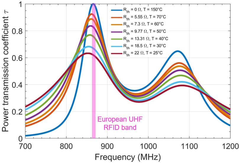
Sensors 2022, 22, 818 4 of 12 1 (4) 1 where 1 1 / ′ ⁄ / ′ / ′ is the step‐up factor, which is equal to 4 when ′. Note that as for any dipole antenna, is depends on the fre‐ quency and is equal to 73 42.5 Ω at the resonance frequency. Finally, it is also worth noting that when 0 Ω, the sensor tag is equivalent to the original RFID yarn with the short‐circuit for the impedance matching circuit. 3. Design and Characterization in Simulation of the RFID Yarn Including a Temperature Sensing 3.1. Geometric Sizing and Parameterization The RFID temperature sensor tag described in Section 2.1 has been designed using the CST Microwave Studio 3D electromagnetic simulation tool. Where the time domain solver has been used based on the Finite Integration Technique (FIT) with a hexahedral adaptive meshing [21]. The RFID temperature sensor tag dimensions, summarized in Ta‐ ble 1, have been optimized for operation in the European UHF RFID band. Table 1. Dimensions of the RFID temperature sensor tag Parameter Dimension (mm) 135 23 0.44 0.06 ′ 0.06 The surrounding textile material has been modeled as a dielectric material with a relative permittivity 2. The chosen thermistor is a negative temperature coefficient (NTC) thermistor [22], which is characterized by a decrease in its resistance for an increase in temperature. 3.2. Impact of a Temperature Variation on the Impedance Matching of the RFID Tag In order to estimate the impact of the temperature change on the power transmission coefficient, the resistance of the thermistor is varied between two limiting values: 0 Ω and 22 Ω, to reflect a decrease in temperature from 150 to 25 °C (corresponding to an aver‐ age ambient temperature). As previously mentioned, for temperature values above 150 °C, the resistance of the thermistor is zero, which can be considered as a short‐circuit: the impedance matching case is then achieved. In the RFID domain, this means that the impedance of the antenna is not equal to a reference impedance (typically 50 ) but is set by the chip. Specifically, it must be equal to the conjugate impedance of the input imped‐ ance of the chip in the energy scavenging state. Figure 2 shows the variation of the tag’s power transmission coefficient, τ, as a func‐ tion of the frequency considering several values of the thermistor resistance to simulate a temperature change (R 0 ; 5.5 ; 7.30 ; 9.77 ; 13.31 ; 18.50 ; 22 ). First, it should be noted that the power transmission coefficient has two resonances that are the result of the two conductors present in the tag: the radiating element of length L and the stub of length L , respectively. If we consider the first resonance (which is in the standard RFID band), we observe an impedance mismatching (i.e., the maximum value of the power transmission coefficient decreases) and at the same time a shift of the reso‐ nance frequency to lower frequencies. Moreover, if we now consider a fixed operating frequency (e.g., 868 MHz), then the variation of the transmission coefficient as a function of temperature can be exploited: this constitutes the principle of the proposed textile thread sensor.
Sensors 2022, 22, 818 5 of 12

 Figure 2. Impact of the thermistor’s resistance change due to temperature on the RFID sensor tag

 4. Experimental Evaluation of the RFID Yarn Including a Temperature Sensor
 4.1. Fabricated RFID Temperature Sensor Tag Yarn
 The designed RFID temperature sensor tag yarn was fabricated using the E‐Thread®
 assembly process. Figure 3 shows a picture of a component of the RFID textile yarn spool;
 the short‐circuit in the matching circuit was replaced by the thermistor.

 Figure 3. Fabricated temperature sensor tag using E‐Thread technology.

 4.2. Temperature Measurement without Environmental Calibration: A Differential Approach
 As shown in the simulation part (Section 3.2), a variation of temperature will imply
 a modification of the power transmission coefficient, and consequently a modification of
 the minimum activation power of the tag. However, the minimum activation power also
 depends on the propagation environment, especially in the vicinity of the tag. Addition‐
 ally, if the propagation environment is modified, this power also varies, and it is no longer
 possible to detect if the observed change is actually related to the temperature or to any
 other parameter of the environment. Consequently, it would be necessary to carry out a
 calibration for a given fixed situation; and for each change of the environment to redo this
 calibration. To overcome this problem, an alternative is proposed by adding a reference
 tag (without detection capability) in the vicinity of the sensor tag. Assuming that the prop‐
 agation channel (i.e., environment) of the two tags is similar, the reference tag will provide
 a reference minimum activation power that depends on the environment but not on the
 temperature. The comparison with the minimum activation power of the sensor tag will
 then allow to deduce the temperature variation. This comparison is simply the difference
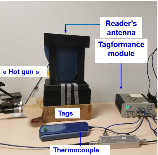
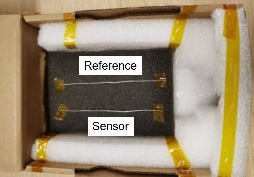
Sensors 2022, 22, 818 6 of 12

 between the two minimum activation powers (with and without sensor) as detailed ana‐
 lytically below to deduce the so‐called differential power. The differential technique has
 been employed in both chipless [23] and UHF RFID [24] sensor tags.
 In a general way, the transmitted power by the reader, , can be written as follows
 [25]:
 dBm (5)
 where dBm is the power received by the tag, dBi is the realized gain of the
 reader antenna, dBi is the antenna gain of the tag, is the power transmission co‐
 efficient, dB is the propagation path loss, and dB is the polarization matching
 coefficient.
 Note that this expression is general and can therefore be used for the reference tag,
 which is performed here using the index 0 for clarity (i.e., the tag is the reference tag char‐
 acterized by and ). Thus, (4) can be also rewritten for the sensor tag as follows:
 (6)
 Where only the term ‘ ’ is modified: in (6), dBi is the antenna gain and is the
 power transmission coefficient, both corresponding to the sensor tag. At the RFID reader’s
 level, it is worth noting that the quantity, , expressed in linear, represents the equiv‐
 alent isotropic radiated power (EIRP). Its maximum value depends on the regulations in
 force according to the geographical area of exploitation; for example, the value imposed
 by the European Telecommunications Standards Institute (ETSI) is 3.28 W.
 With the powers and that correspond to the minimum activation power for
 each of the tags (reference and sensor), the power difference, here called differential
 power, is necessary to activate, on the one hand, the reference tag and, on the other hand,
 the sensor tag will be an image of the temperature and given by the following expression:
 ∆ dB (7)

 4.3. Experimental Setup
 The complete measurement protocol is presented in Figure 4. The reference tag and
 the temperature sensor tag are placed in a closed box as shown in Figure 4b. The two tags
 are aligned and separated by a distance of 4 cm. This distance is relatively small. It has
 been verified that it does not lead to a significant mutual coupling effect between the two
 tags. Moreover, it allows to assume that the propagation channels for each tag are similar.
 The temperature inside the box containing the two tags is controlled with a hot air
 gun, and its temperature is measured with a thermocouple. The temperature range to
 which the tags are subjected varies from 25 to 70 °C. The maximum temperature was set
 at 70 °C in practice in order not to alter the tags. The RF measurements are performed
 using the Tagformance Pro bench [26] for the 800–1200 MHz frequency range. This bench
 allows to activate the tags according to the ISO 18000‐6c protocol.
Sensors 2022, 22, 818 7 of 12

 (a) (b)
 Figure 4. Experimental setup: (a) measurement setup elements; (b) RFID temperature sensor tag
 (at the bottom) and reference tag (at the top) placement environment.

 Using the described experimental setup here above, the differential power extraction
 can be summarized in few steps: (i) the reader’s transmitted power is gradually increased
 for the sensor tag and the reference tag one after another; (ii) the reading process is
 stopped once the IDs of the tags (sensor + reference) are returned and respective activation
 transmitted powers are extracted; (iii) the differential power ∆ is calculated for a given
 temperature. Finally, from the obtained result, by using a calibration curve, a temperature
 value can be attributed to every differential power. Figure 5 shows a diagram that sum‐
 marizes the described protocol.

 Figure 5. The proposed methodology of temperature extraction with a differential approach using
 a commercial RFID reader.
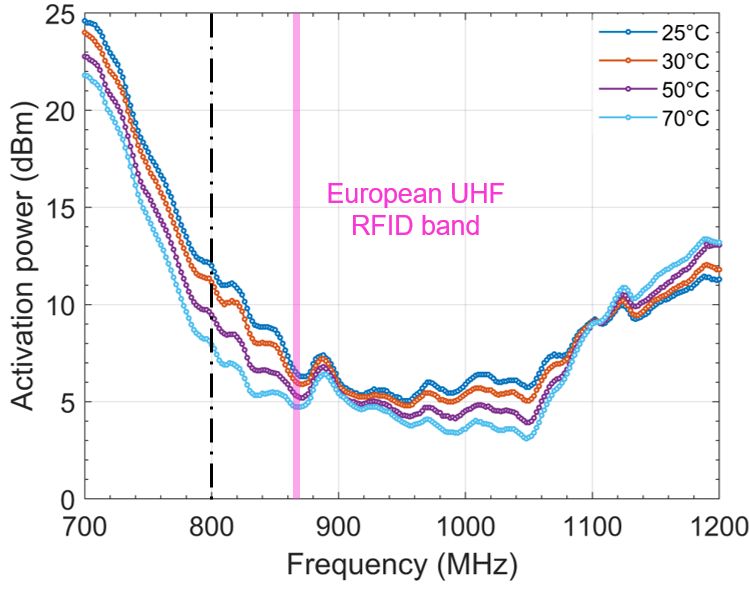
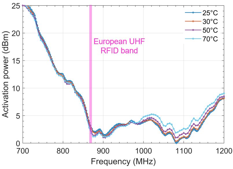
Sensors 2022, 22, 818 8 of 12

 5. Measurement Results and Discussion
 5.1. Impact of the Temperature Change on the Transmitted Differential Activation Power
 Figures 6 and 7 show the activation power required for the reference tag and the
 sensor tag, respectively. The reference tag is practically not impacted by the temperature
 increase for the first resonance frequency (which is the frequency of interest). The temper‐
 ature impacts the highest frequencies, which can be explained by the premise of expansion
 of the conductors when temperatures increase. However, this is of no consequence for the
 application and the considered frequency range.
 In the case of the sensor tag, as expected and detailed in the theoretical part, the min‐
 imum activation power decreases when the temperature increases. However, if the con‐
 cept is experimentally validated, sensitivity could apparently be improved. Indeed, for a
 frequency around 800 MHz, the impact of the temperature variation is more accentuated.

 Figure 6. Impact of the temperature on the activation power of the reference tag.

 Figure 7. Impact of the temperature on the activation power of the sensor tag.
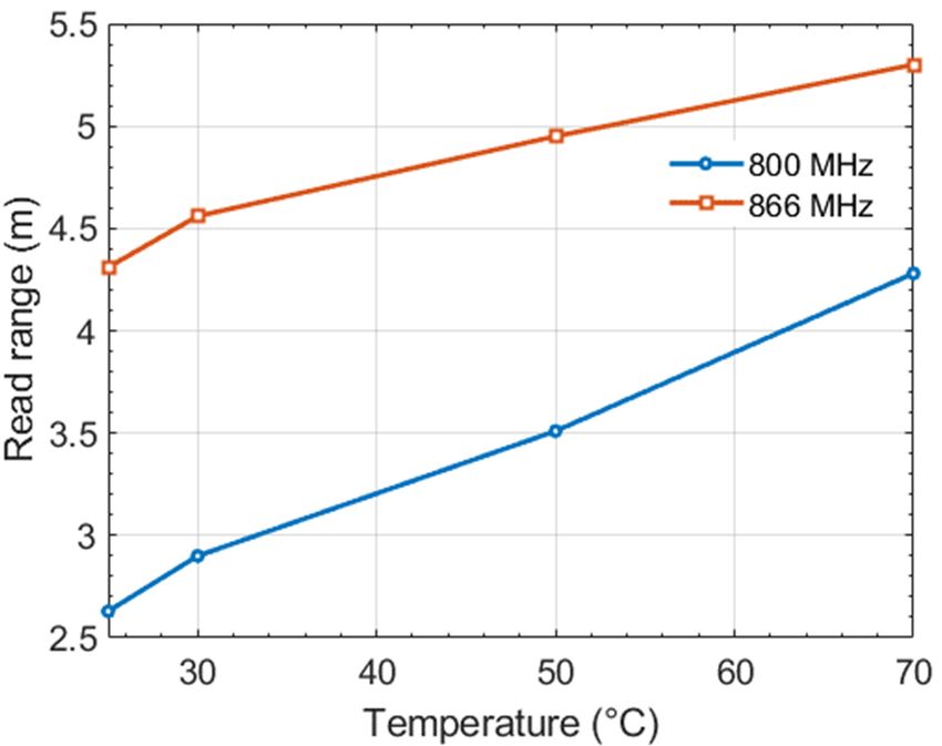
Sensors 2022, 22, 818 9 of 12

 Figure 8 shows the variation of temperature versus differential power assuming two
 operating frequencies for illustration and proof of concept: 800 and 866 MHz. It can be
 observed that a decrease in the temperature value corresponds to an increase of the dif‐
 ferential power level, which is coherent with (7). Moreover, a quasi‐linear behavior of the
 temperature in the range of 40 70 °C can be noticed and corresponds to slopes (abso‐
 lute value) of 11.4 and 33.3 °C/dB at the frequencies 800 and 866 MHz, respectively.
 It is important to notice that the temperature value extraction depends strongly on the
 reader in terms of the transmitted power resolution. Consequently, the smaller the temper‐
 ature slope, the easier it is to extract the temperature value. In the current state, it may be
 concluded that at 866 MHz, the sensor tag is more suited for a temperature threshold detec‐
 tion than for an exact temperature value. On the contrary, for an operating frequency of
 800 MHz a temperature detection in terms of absolute values may be considered.

 Figure 8. Temperature deducing using differential activation power method.

 5.2. Impact of the Temperature Change on the Read Range
 The method presented above allows an estimation of the temperature using an ap‐
 proach based on the differential activation power that can be applied using a commercial
 RFID reader. In the RFID context, the read range is an important criterion that character‐
 izes the performance of the tag and is highly dependent on its impedance matching. It
 seemed interesting to evaluate the impact of the temperature variation on this quantity.
 As expected, it is observed in the Figure 9, that the reading distance increases when
 the temperature is increasing since the impedance matching improves. For the operating
 frequency equal to 800 MHz, when the temperature varies from 25 to 70 °C, the reading
 distance varies from 2.6 to 4.3 m. On the other hand, when the operating frequency is
 866 MHz, the reading distance varies from 4.3 to 5.3 m. It can also be seen that the read‐
 ing distance range is greater with the 800 MHz frequency than with the 866 MHz fre‐
 quency, which reflects the better resolution obtained for the sensor.
 Consequently, in sensor mode, this study shows the limits of use in terms of mini‐
 mum reading distance to use the sensor. At full scale (here from 25 to 70 °C), the distance
 between reader and tag should not exceed 2.6 m at the 800 MHz frequency and 4.3 m at
 the 866 MHz frequency; otherwise the tag will not be read for the minimum temperature
 equal to 25 °C. From this point of view, the performance is better for the 866 MHz fre‐
 quency. Ideally, two opposing criteria should be maximized: on the one hand, maximizing
 the reading distance for the most unsuitable case (here, a temperature equal to 25° ), and
Sensors 2022, 22, 818 10 of 12

 on the other hand, maximizing the reading distance range when the temperature varies
 to obtain a better resolution for the sensor.

 Figure 9. Impact of the temperature on the sensor’s read range.

 5.3. Analysis of the Temperature RFID Sensor Integrated in a Textile Yarn and Comparison with
 the Existing Solutions Presented by the Literature
 Table 2 presents the properties of wearable UHF RFID temperature sensor tags exist‐
 ing in the literature [9,10] [27]. In each work, the sensor is integrated into the RFID chip
 that can operate in a passive mode but with a degraded performance or in semi‐passive
 mode (integrated battery). The proposed solution allows maintaining the same manufac‐
 turing process than the E‐Thread® RFID yarn with the advantage of a slender form factor
 that simplifies its integration in any object and, more importantly, the passive property of
 the tag is conserved.

 Table 2. Comparison between the properties of the UHF RFID temperature sensor tag integrated in
 a textile yarn with solutions existing in the literature.

 Reference Fabrication Method Substrate Sensing Principle UHF Band
 [10] Screen printing Plastic RFID chip integrated sensor SL900A US: 902– 928 MHz
 [9] 3D printing Flexible polyimide RFID chip integrated sensor SL900A US: 902– 928 MHz
 [27] 3D printing Polylactic RFID chip integrated sensor EM4325 UE: 864.5 867.5 MHz
 Tag properties
Current work E‐Thread® No substrate UE: 864.5 867.5 MHz
 (impedance matching)

 6. Conclusions and Future Work
 This paper presents an RFID temperature sensor tag integrated into a textile yarn.
 The operation principle of the sensor tag is based on the impedance mismatching due to
 variation of the resistance of a thermistor as function of temperature. The RFID tempera‐
 ture sensor yarn was fabricated and experimentally characterized. The results validate the
 proposed approach by the variation of the activation power due to the temperature
 change. Moreover, a method to avoid a calibration phase before the measurement has
 been proposed and consists in using a reference tag by assuming that it is subjected to the
 same temperature change and has the same propagation channel. This assumption allows
Sensors 2022, 22, 818 11 of 12

 the calculation of a differential power, which is directly proportional to the temperature
 variation.
 The results show that in the European UHF RFID band (866 MHz), the temperature
 sensor tag has the potential to detect a temperature variation of 33.3 °C with 1 dB of dif‐
 ferential power. Thus, the sensor tag is more suitable for temperature threshold detection.
 However, it has been observed that at a frequency below resonance (i. e. , 800 MHz), it is
 possible to detect a temperature variation of 11.4 °C with 1 dB of differential power. In
 the future, it would be suitable to obtain a similar sensitivity for the sensor tag in UHF
 RFID band. One solution would be to shift the resonant frequency to higher frequencies,
 which will require higher activation power levels and ultimately increase the sensitivity
 of the sensor tag. In the other hand, for an application scenario that does not implies the
 use of two tags, it could be interesting to exploit a temperature range where the sensor tag
 exhibits a linear behavior with a fixed temperature curve slope. Indeed, a calibration step
 would be necessary when the environment is changed, however, around only a single
 temperature point. Thus, the complete data can be deduced simply by the shift of the
 original curve of temperature versus the transmitted threshold power, obtained initially
 in a given environment.
 Finally, it is important to notice that the proposed UHF RFID temperature sensor has
 a great potential to be used in medical applications where it can provide a wearer’s tem‐
 perature level. However, the performance of the RFID tag, especially in terms of imped‐
 ance matching, can be degraded in the presence of the human body. In our case, the im‐
 pact will be applied on both the reference tag and the sensor tag and can then degrade the
 reading sensitivity range. In this case, it is possible to ensure a certain robustness by con‐
 sidering from the design stage constraints related to the environment. Presently, we have
 assumed free space but it will be possible to add a human body model (even a simple one
 modeled by several layers of superimposed substrates to anticipate the impact). This does
 not call into question the concept proposed in our study.

 Author Contributions: conceptualization, S.B.; methodology, S.B., F.D.H., and Y.D.; software, S.B.;
 validation, S.B., F.D.H., and Y.D.; formal analysis, S.B.; investigation, S.B., F.D.H., and Y.D.; writ‐
 ing—original draft preparation, S.B.; writing—review and editing, F.D.H. and Y.D.; supervision,
 F.D.H. and Y.D.; funding acquisition, Y.D. All authors have read and agreed to the published ver‐
 sion of the manuscript.
 Funding: This research was funded by the “La Région Auvergne Rhône‐Alpes” Lyon, France,
 through the “Pack Ambition Recherche 2017” program.
 Acknowledgments: The authors would like to thank the company Primo1D for their help during
 the manufacturing process and the experimental characterization.
 Conflicts of Interest: The authors declare no conflict of interest.

References
1. Athauda, T.; Karmakar, N. Chipped versus chipless RF identification: A comprehensive review. IEEE Microw. Mag. 2019, 20,
 47–57.
2. Aiswarya, S.; Menon, S.K.; Donelli, M. Development of enhanced range, high Q, passive, chipless RFID tags for continuous
 monitoring and sensing applications. Electronics 2022, 11, 127.
3. Marchi, G.; Mulloni, V.; Hammad Ali, O.; Lorenzelli, L.; Donelli, M. Improving the sensitivity of chipless RFID sensors: The
 case of a low‐humidity sensor. Electronics 2021, 10, 2861.
4. Corchia, L.; Monti, G.; De Benedetto, E.; Cataldo, A.; Angrisani, L.; Arpaia, P.; Tarricone, L. Fully‐textile, wearable chipless tags
 for identification and tracking applications. Sensors 2020, 20, 429.
5. Barbot, N.; Rance, O.; Perret, E. Classical RFID versus chipless RFID read range: is linearity a friend or a foe? IEEE Trans. Microw.
 Theory Tech. 2021, 69, 4199–4208.
6. Zannas, K.; El Matbouly, H.; Duroc, Y.; Tedjini, S. Augmented RFID Tags: From Identification to Sensing. 2020. Available online:
 https://hal.archives‐ouvertes.fr/hal‐03389481/ (accessed on 25 April 2021).
7. Ams. SL900A EPC Gen2 Sensor Tag. Available online: https://ams.com/SL900A (accessed on 25 April 2021).
8. Virtanen, J.; Ukkonen, L.; Björninen, T.; Sydänheimo, L. Printed humidity sensor for UHF RFID systems. In Proceedings of the
 IEEE Sensors Applications Symposium (SAS), Limerick, Ireland, 23–25 February 2010.
Sensors 2022, 22, 818 12 of 12

9. Trangkanukulkij, R.; Kim, T.; Kim, W.S. A 3D printed flexible passive RFID for temperature sensing. In Proceedings of the
 International Flexible Electronics Technology Conference (IFETC), Ottawa, ON, Canada, 7–9 August 2018.
10. Baumbauer, C.L.; Anderson, M.G.; Ting, J.; Sreekumar, A.; Rabaey, J.M.; Arias, A.C.; Thielens, A. Printed, flexible, compact
 UHF‐RFID sensor tags enabled by hybrid electronics. Sci. Rep. 2020, 10, 16543.
11. Virtanen, J.; Ukkonen, L.; Bjorninen.; Elsherbeni, A.Z.; Sydänheimo, L. Inkjet‐printed humidity sensor for passive UHF RFID
 systems. IEEE Trans. Instrum. Meas. 2011, 60, 2768–2777.
12. Chen, X.; He, H.; Ukkonen, L.; Virkki, J. Embroidered UHF RFID moisture sensor tag on dishcloth substrate. In Proceedings of
 the IEEE International Symposium on Antennas and Propagation & USNC/URSI National Radio Science Meeting, Boston,
 MA, USA, 8–13 July 2018.
13. Andia, G. Slenderly and Conformable Passive UHF RFID Yarn. In Proceedings of the IEEE International Conference on RFID,
 Phoenix, AZ, USA, 9–11 May 2017.
14. Vicard, D.; Brun, J. Cap for a Chip Device Having a Groove, Device Provided with Said Cap, Assembly Consisting of the De‐
 vice and a Wire Element, and Manufacturing Method Thereof. U.S. Patent EP2896067B1, 1 February 2017.
15. Benouakta, S.; Hutu, H.; Duroc, D. Passive UHF RFID yarn for temperature sensing applications. In Proceedings of the IEEE
 International Conference on RFID Technology and Application (RFID‐TA), Delhi, India, 6–8 October 2021.
16. Impinj. Monza 6 Product Brief. Available online: https://sensorplaza.nl/wp‐content/uploads/2017/06/Monza‐R6P‐
 Datasheet.pdf (accessed on 15 March 2021).
17. Merilampi, S.; He, H.; Sydänheimo, L.; Ukkonen, L.; Virkki, J. The possibilities of passive UHF RFID textile tags as comforta‐
 ble wearable sweat rate sensors. In Proceedings of the Progress in Electromagnetic Research Symposium (PIERS), Shanghai,
 China, 8–11 August 2016.
18. Seshagiri Rao, K.V.; Nikitin, P.V.; Lam, S.F. Antenna design for UHF RFID tags: a review and a practical application. IEEE
 Trans. Antennas Propag. 2005, 53, 3870–3876.
19. Tolles, H.T. How to design gamma‐matching networks. Ham. Radio 1973, 46–55. Available online: https://www.nonstopsys‐
 tems.com/radio/pdf‐ant/article‐antenna‐gamma‐match‐HR73.pdf (accessed on 17 January 2022).
20. Balanis, C.A. Antenna Theory Analysis and Design, 3rd ed.; John Wiley & Sons: Hoboken, NJ, USA, 2005.
21. CST Microwave 3D Studio. Available online: https://www.3ds.com/fr/produits‐et‐services/simulia/produits/cst‐studio‐suite/
 (accessed on 17 January 2022).
22. Murata. NTC Thermistors. Available online: https://www.murata.com/en‐eu/products/thermistor/ntc (accessed on 14 February
 2021).
23. Unnikrishnan, R.; Rance, O.; Barbot, N.; Perret, E. Chipless RFID label with identification and touch‐sensing capabilities. Sensors
 2021, 21, 4862.
24. Kim, S.; Kawahara, Y.; Georgiadis, A.; Collado, A.; Tentzeris, M.M. Low‐cost inkjet‐printed fully passive RFID tags for calibra‐
 tion‐free capacitive/haptic sensor applications. IEEE Sens. J. 2015, 15, 3135–3145.
25. Nikitin, P.V.; Rao, K.V.S. Performance limitations of passive UHF RFID systems. In Proceedings of the IEEE Antennas and
 Propagation Society International Symposium, Albuquerque, NM, USA, 9–14 July 2006.
26. Voyantic. Tagformance Pro. Available online: https://voyantic.com/products/tagformance‐pro (accessed on 2 February 2021).
27. Colella, R.; Catarinucci, L. Wearable UHF RFID sensor tag in 3D‐printing technology for body temperature monitoring. In
 Proceedings of the URSI Atlantic Radio Science Meeting (AT‐RASC), Gran Canaria, Spain, 28 May–1 June 2018.
You can also read


