Unifying Performance and Security Evaluation for Microarchitecture Design Exploration - Northeastern University
←
→
Page content transcription
If your browser does not render page correctly, please read the page content below
Unifying Performance and Security Evaluation for Microarchitecture
                           Design Exploration

                               A Thesis Presented
                                        by

                                  Griffin Knipe

                                        to

            The Department of Electrical and Computer Engineering

                     in partial fulfillment of the requirements
                                 for the degree of

                                Master of Science

                                        in

                             Electrical Engineering

                            Northeastern University
                             Boston, Massachusetts

                                  April 20, 2021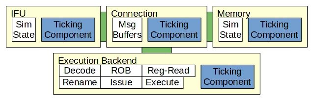
To Krina, for sharing your determination to a life of play.

                            i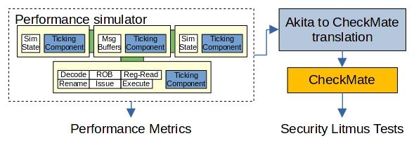
Contents

List of Figures                                                                                                                               iv

List of Tables                                                                                                                                 v

Acknowledgments                                                                                                                               vi

Abstract of the Thesis                                                                                                                        vii

1   Introduction                                                                                                                               1

2   Background                                                                                                                                 3
    2.1 Instruction Set Architecture . . . . . . . . . . . .          .   .   .   .   .   .   .   .   .   .   .   .   .   .   .   .   .   .    3
        2.1.1 Architectural State . . . . . . . . . . . .             .   .   .   .   .   .   .   .   .   .   .   .   .   .   .   .   .   .    3
        2.1.2 Assembly . . . . . . . . . . . . . . . . .              .   .   .   .   .   .   .   .   .   .   .   .   .   .   .   .   .   .    3
        2.1.3 Virtual Memory . . . . . . . . . . . . . .              .   .   .   .   .   .   .   .   .   .   .   .   .   .   .   .   .   .    4
    2.2 Microarchitecture . . . . . . . . . . . . . . . . .           .   .   .   .   .   .   .   .   .   .   .   .   .   .   .   .   .   .    4
        2.2.1 Pipelining . . . . . . . . . . . . . . . . .            .   .   .   .   .   .   .   .   .   .   .   .   .   .   .   .   .   .    5
        2.2.2 Handling Control-flow Instructions . . .                .   .   .   .   .   .   .   .   .   .   .   .   .   .   .   .   .   .    7
        2.2.3 Data Hazards in the 5-stage Pipeline . . .              .   .   .   .   .   .   .   .   .   .   .   .   .   .   .   .   .   .    8
        2.2.4 Out-of-order Execution . . . . . . . . . .              .   .   .   .   .   .   .   .   .   .   .   .   .   .   .   .   .   .    8
        2.2.5 Memory Hierarchy . . . . . . . . . . . .                .   .   .   .   .   .   .   .   .   .   .   .   .   .   .   .   .   .    9
        2.2.6 Transient Instructions . . . . . . . . . . .            .   .   .   .   .   .   .   .   .   .   .   .   .   .   .   .   .   .   10
        2.2.7 Side-channels . . . . . . . . . . . . . . .             .   .   .   .   .   .   .   .   .   .   .   .   .   .   .   .   .   .   10
        2.2.8 Transient Execution Side-channel Attacks                .   .   .   .   .   .   .   .   .   .   .   .   .   .   .   .   .   .   11
    2.3 Microarchitectural Security Verification . . . . .            .   .   .   .   .   .   .   .   .   .   .   .   .   .   .   .   .   .   12

3   Related Work                                                                                                                              13
    3.1 Performance Simulators . . . . . . . . . .    .   .   .   .   .   .   .   .   .   .   .   .   .   .   .   .   .   .   .   .   .   .   13
         3.1.1 Akita . . . . . . . . . . . . . . .    .   .   .   .   .   .   .   .   .   .   .   .   .   .   .   .   .   .   .   .   .   .   14
    3.2 Formal Methods for Security Evaluation .      .   .   .   .   .   .   .   .   .   .   .   .   .   .   .   .   .   .   .   .   .   .   14
         3.2.1 CheckMate . . . . . . . . . . . .      .   .   .   .   .   .   .   .   .   .   .   .   .   .   .   .   .   .   .   .   .   .   15
    3.3 Software Implementation Error Catching .      .   .   .   .   .   .   .   .   .   .   .   .   .   .   .   .   .   .   .   .   .   .   16

                                                 ii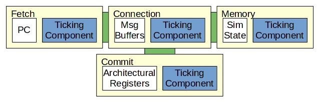
4   Yori                                                                                                                               18
    4.1 VEmu . . . . . . . . . . . . . . . . . . . . . . .     .   .   .   .   .   .   .   .   .   .   .   .   .   .   .   .   .   .   18
         4.1.1 Verification and Performance . . . . . . .      .   .   .   .   .   .   .   .   .   .   .   .   .   .   .   .   .   .   18
    4.2 Microarchitecture Simulation . . . . . . . . . . .     .   .   .   .   .   .   .   .   .   .   .   .   .   .   .   .   .   .   19
         4.2.1 Instruction Fetch Unit . . . . . . . . . .      .   .   .   .   .   .   .   .   .   .   .   .   .   .   .   .   .   .   20
         4.2.2 Memory Unit . . . . . . . . . . . . . . .       .   .   .   .   .   .   .   .   .   .   .   .   .   .   .   .   .   .   21
         4.2.3 Execution Backend Overview . . . . . .          .   .   .   .   .   .   .   .   .   .   .   .   .   .   .   .   .   .   21
         4.2.4 Decode . . . . . . . . . . . . . . . . . .      .   .   .   .   .   .   .   .   .   .   .   .   .   .   .   .   .   .   22
         4.2.5 Register-rename . . . . . . . . . . . . .       .   .   .   .   .   .   .   .   .   .   .   .   .   .   .   .   .   .   22
         4.2.6 Reorder-Buffer . . . . . . . . . . . . . .      .   .   .   .   .   .   .   .   .   .   .   .   .   .   .   .   .   .   24
         4.2.7 Issue . . . . . . . . . . . . . . . . . . .     .   .   .   .   .   .   .   .   .   .   .   .   .   .   .   .   .   .   24
         4.2.8 Register-read . . . . . . . . . . . . . . .     .   .   .   .   .   .   .   .   .   .   .   .   .   .   .   .   .   .   24
         4.2.9 Execute . . . . . . . . . . . . . . . . . .     .   .   .   .   .   .   .   .   .   .   .   .   .   .   .   .   .   .   25
         4.2.10 Memory Operation Ordering Exception .          .   .   .   .   .   .   .   .   .   .   .   .   .   .   .   .   .   .   25
         4.2.11 Verification . . . . . . . . . . . . . . . .   .   .   .   .   .   .   .   .   .   .   .   .   .   .   .   .   .   .   26
         4.2.12 Performance Discussion . . . . . . . . .       .   .   .   .   .   .   .   .   .   .   .   .   .   .   .   .   .   .   26
    4.3 CheckMate Integration . . . . . . . . . . . . . .      .   .   .   .   .   .   .   .   .   .   .   .   .   .   .   .   .   .   28
         4.3.1 Communication Challenges . . . . . . .          .   .   .   .   .   .   .   .   .   .   .   .   .   .   .   .   .   .   29
         4.3.2 Undesirable Solutions . . . . . . . . . .       .   .   .   .   .   .   .   .   .   .   .   .   .   .   .   .   .   .   33
         4.3.3 Request Driven Simulation . . . . . . . .       .   .   .   .   .   .   .   .   .   .   .   .   .   .   .   .   .   .   33
         4.3.4 3-stage model translation to CheckMate. .       .   .   .   .   .   .   .   .   .   .   .   .   .   .   .   .   .   .   34
         4.3.5 Yori as a Request Driven Simulator . . .        .   .   .   .   .   .   .   .   .   .   .   .   .   .   .   .   .   .   34
         4.3.6 Remaining Challenges for Integration . .        .   .   .   .   .   .   .   .   .   .   .   .   .   .   .   .   .   .   38

5   Conclusion                                                                                                                         40
    5.1 Contributions of this Thesis . . . . . . . . . . . . . . . . . . . . . . . . . . . . . .                                       41
    5.2 Future Work . . . . . . . . . . . . . . . . . . . . . . . . . . . . . . . . . . . . . .                                        41

Bibliography                                                                                                                           43

                                                  iii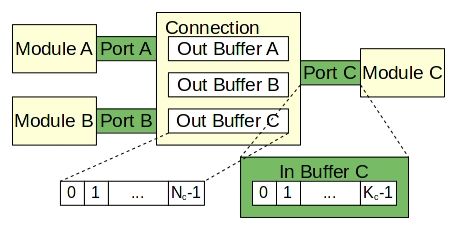
List of Figures

 2.1   MIPS ISA single-cycle data-path (from Harris and Harris [1]). . . . . . . . . . . .         5
 2.2   Simple 5-stage RISC-V pipelined data-path (from Hennessy and Patterson [2]). . .            6

 3.1   High-level Akita component topology. . . . . . . . . . . . . . . . . . . . . . . . .       14
 3.2   A generalized happens-before graph depicting two instructions traversing three stages
       in a microarchitecture. . . . . . . . . . . . . . . . . . . . . . . . . . . . . . . . .    16

 4.1  A high-level view of Yori’s simulation components. . . . . . . . . . . . . . . . . .        20
 4.2  Communication flow between stages in the Execution Backend. . . . . . . . . . .             22
 4.3  High-level software topology of tools facilitating performance simulation and security
      evaluation. . . . . . . . . . . . . . . . . . . . . . . . . . . . . . . . . . . . . . . .   28
 4.4 Akita model component topology for simple 3-stage pipeline. . . . . . . . . . . . .          29
 4.5 Generic Akita connection employing default message buffering structures. . . . . .           30
 4.6 The sequence of operations corresponding to default message handling in the 3-stage
      model. . . . . . . . . . . . . . . . . . . . . . . . . . . . . . . . . . . . . . . . . .    31
 4.7 Sequence of operations, following the cycle shown in Figure 4.6, causing back-
      pressure in the 3-stage model. . . . . . . . . . . . . . . . . . . . . . . . . . . . .      32
 4.8 Sequence of operations for request-driven communication design. . . . . . . . . .            35
 4.9 Event-message sequence diagram for the 3-stage model Fetch stage. . . . . . . . .            36
 4.10 Event-message sequence diagram for the 3-stage model Commit stage. . . . . . . .            37
 4.11 Event-message sequence diagram for the 3-stage model Memory Unit. . . . . . . .             37
 4.12 Messaging overview for Yori Execution Backend as a request driven simulation. . .           38

                                                iv
List of Tables
4.1 Shown here are the transient instruction window lengths, measured in number of
instructions, for the median micro-benchmark [3] on Yori and Verilator simulators.
Yori’s transient instruction window is far shorter than that of the Verilator model, on
average. This motivates additional work for Yori to faithfully model SonicBOOM
transient execution attacks. . . . . . . . . . . . . . . . . . . . . . . . . . . . . . . 26
4.2 Shown here is the CPI, measured in cycles, for the Yori simulation, running the
median micro-benchmark [3]. Measurements are categorized by instruction type,
as each type executes through a different hardware path. ALU and Jmp instructions
both use the ALU functional unit of the Execute stage. Mem and CSR instructions
use the CSR Unit and LSU, respectively. . . . . . . . . . . . . . . . . . . . . . . . 27
4.3 Shown here is the CPI, measured in cycles, for the Verilator simulation, running the
median micro-benchmark [3]. Measurements are categorized by instruction type
as each type executes through a different hardware path. . . . . . . . . . . . . . . 27
vAcknowledgments
First, I’d like to thank Dr. David Kaeli, who generously accepted me into NUCAR and
supported me through my first research experience. He gave me the freedom to explore an unfamiliar
field, and with that countless opportunities to grow as an engineer, as a student, and as a person.
Next, I’d like to thank Dr. Yunsi Fei for her feedback and guidance in this work.
Thank you to Mike Ridge and Andrew Stone for encouraging me to pursue, and ultimately
secure, a Draper research fellowship. Andrew has been a key mentor in my engineering education
through multiple internships and work opportunities.
To my peers at NUCAR, I am inspired by your work and determination. Thank you for
welcoming me into your group and sharing your thoughts and ideas. I hope we can work together
again in the future.
To Mom, Dad, and Bella, I wouldn’t be here if not for your love and support. Thank you.
viAbstract of the Thesis
Unifying Performance and Security Evaluation for Microarchitecture
Design Exploration
by
Griffin Knipe
Master of Science in Electrical Engineering
Northeastern University, April 20, 2021
Dr. David Kaeli, Advisor
Computer architects develop microarchitectural features that boost instruction-level paral-
lelism to improve CPU performance. While performance may be improved, adding new features
increases the CPU’s design complexity. This further compounds the effort required to complete
design verification. Trustworthy design verification is paramount to microarchitecture design, as
silicon chips cannot easily be patched in the field.
Despite the best efforts for security verification, researchers have created transient execution
side-channel attacks which can exploit microarchitecture performance features to leak data across
ISA-prescribed security boundaries. This motivates the unification of performance evaluation and
security verification techniques to ensure that new microarchitectural features are understood from
multiple design perspectives.
This thesis presents Yori, a RISC-V microarchitecture simulator that aims to enable
computer architects to evaluate microarchitecture performance and security using a single framework.
As Yori is a work-in-progress, this thesis presents the work-to-date, focusing on a detailed model of
the reference microarchitecture and evaluation of the current model accuracy. We describe a viable
methodology to interface between the Yori simulator and an existing security verification tool. We
conclude the thesis, laying out a plan to complete this marriage of performance and security.
viiChapter 1
Introduction
Computer architects work to improve a CPU’s power efficiency, reliability, form-factor,
security and performance with each CPU design iteration. These design aspects are tightly coupled,
such that microarchitectural features aimed at addressing a subset of the design aspects will surely
affect the others. This observation is supported by the discovery of transient execution side-channel
attacks [4, 5, 6, 7, 8], which exploit microarchitectural performance features that violate security
constraints. Malicious attackers can use these exploits to uncover protected data on common
consumer CPUs.
Transient execution side-channel attacks come in many varieties. They differ in their
design in how they exploit attack triggers [4, 5] and achieve data leakage [9, 10]. Designers have
produced new microarchitectural defenses that are resilient to previously known attacks, though
researchers continue to discover new sets of attacks daily on new designs [6]. Such cases highlight
how secure microarchitecture design is always playing catch-up with new vulnerabilities. Researchers
can create software mitigations for existing microarchitectures and hardware mitigations for future
microarchitectures, but these protections incur a performance cost [11]. This overhead is typically
unacceptable for an industry whose consumers expect a device to be secure and performant for its
lifetime. This challenge motivates us to explore a new approach to microarchitecture design.
Ongoing research for a new approach to microarchitecture design centers around the
RISC-V [12] instruction set architecture (ISA). RISC-V is a customizable, open-source, ISA that
is activively being studied across a large and growing research community. By utilizing RISC-V,
research projects may leverage free and sophisticated microarchitecture designs [13, 14, 15], have
access to ever-expanding software support [16], and utilize a rich set of microarchitectural simulation
tools [17, 18, 19].
1CHAPTER 1. INTRODUCTION
This thesis presents Yori, a RISC-V microarchitecture simulator that aims to marry per-
formance characterization with the formal verification of security constraints. Where these types of
evaluations currently require a designer to implement the microarchitecture in separate frameworks,
this tool should support both given a single imperative description of the hardware.
This thesis is organized as follows. In Chapter 2 we review many of the background
concepts utilized in this work. Chapter 3 describes prior work on the class of problems that Yori is
targeting. Chapter 4 presents Yori, and provides an analysis of its performance. The thesis concludes
with Chapter 5 and includes a discussion of directions for future work.
2Chapter 2
Background
2.1 Instruction Set Architecture
The ISA defines a program’s perspective of hardware state during program execution and
the operations by which the program can update the hardware state [2]. In essence, an ISA describes
the interface between software and the logical data structures on-chip. Programmers and computer
architects must adhere to the ISA to ensure correct program execution. Here, the state of the logical
data structures exposed by the ISA will be referred to as the architectural state.
2.1.1 Architectural State
Consider the base configuration of the RISC-V ISA known as RV64I. The qualifier RV64I
indicates that the ISA is configured to operate upon 64-bit integer data. The architectural state
exposed in this configuration includes 32 integer registers, 4096 control-status registers (CSR), and
264 bytes of memory [12]. The program stores its execution state in these architectural data structures
and operates upon the data to carry-out the behavior described by the programmer.
2.1.2 Assembly
The operations for updating architectural state are known as assembly instructions. A
programmer creates a program by writing assembly instructions manually or by describing the
program’s behavior using a high-level programming language. A compiler translates the high-
level programming language to assembly instructions. For instance, programs written in the C
programming language [20] are translated to assembly by a compiler, such as GCC [21].
3CHAPTER 2. BACKGROUND
Each instruction is encoded as a bit-word which corresponds to the instruction’s operation
and, for some instructions, data operands and destinations. An RV64I instruction can be classified
as an arithmetic, control-flow, or data-transfer instruction [2]. Arithmetic instructions complete a
mathematic operation, given its register operands, and write the result to the destination register
(e.g. add, sub). Control-flow instructions enable non-linear instruction execution by indicating
which instruction should execute following the control-flow instruction (e.g. beq). This class of
instructions also includes instructions for enforcing memory operation order (e.g. fence). Data-
transfer instructions facilitate the movement of data between the data registers and memory (e.g. lw,
sw).
2.1.3 Virtual Memory
The RISC-V ISA also provides the means for multi-program execution where multiple
programs may execute concurrently on shared hardware [2]. To account for potentially malicious
software sharing hardware with other programs, the ISA prescribes that one program cannot covertly
access the data of another program. This is one of the motivations behind virtual memory [2, 12]
which gives each program an independent perspective of physical memory [2]. Physical memory
refers to the memory address to data translation that exists on hardware. Virtual memory maps
different portions of physical memory to each program. The virtual memory system provides an
extra layer of address translation to hide the exact location of this data in physical memory. That
is, a program uses a virtual memory address to access memory which the hardware translates to a
physical memory address. The hardware can then access the data at that physical address without the
program knowing where that data lies in hardware.
Note that there are cases where programs may share portions of virtual memory to facilitate
communication or to reduce memory utilization where multiple programs read the same data [2]. By
sharing certain portions of virtual memory address space, the programs also share portions of the
corresponding physical memory address space.
2.2 Microarchitecture
The microarchitecture design comprises the physical circuit implemented on-chip. It
exposes the interface described by the ISA while accounting for real-world constraints, including
power, reliability, chip utilization, and financial cost. To balance these constraints with the need
4CHAPTER 2. BACKGROUND
for performance, a microarchitecture may generate and track state, in addition to architectural state.
Here, this will be referred to as microarchitectural state.
Computer architects can use microarchitectural state to employ clever algorithms to im-
prove a chip design. As execution progresses and an instruction completes, its microarchitectural
state will be made available to the program as architectural state. It is the computer architect’s
responsibility to ensure that microarchitectural state is not revealed as architectural state in such
a way that violates the ISA. Such cases can cause data leakage [9, 10] across boundaries pre-
scribed by the ISA [22]. Here, we’ll review a few fundamental microarchitectural features and the
microarchitectural state that each generates.
2.2.1 Pipelining
Consider the single-cycle data-path [1] shown in Figure 2.1. The data-path shown here is
intended for the MIPS ISA [23], but is conceptually consistent with a RISC-V single-cycle data-path.
This data-path executes one instruction per cycle (IPC), which is a measurement of the number of
instructions to complete in one clock cycle [2]. The clock signal drives the timing of state updates in
the data-path.
Branch Resolution
Write-
Fetch Decode Execute Memory
Back
Figure 2.1: MIPS ISA single-cycle data-path (from Harris and Harris [1]).
Referring to Figure 2.1, the instruction completes its operation as it travels from left-to-
right in a single cycle. The data-path first retrieves the instruction from Instruction Memory. The
instruction operands are retrieved from the Register File or are decoded as an immediate value
from the instruction word. The Arithmetic Logic Unit (ALU) completes the operation for the given
operands. If the instruction is a data-transfer instruction, it can access memory at the Data Memory
module. Last, the instruction may write data to the Register File. In this design, writing to the Data
Memory module or to the Register File reveals new architectural state.
5CHAPTER 2. BACKGROUND
Since these operations occur in one cycle, the clock speed is restricted by the time it takes
for all hardware modules in the data-path to complete its operation [1]. This time value is found by
calculating the sum of time required by each module. This design leaves much of the hardware idle
during a cycle as only one module is doing work at a given time. These performance flaws motivate
data-path pipelining [2] which improves the maximum clock speed and reduces the amount of idle
hardware. Mitigating these flaws increases instruction throughput and thus data-path performance.
Branch Resolution
Write-
Fetch Decode Execute Memory
Back
Figure 2.2: Simple 5-stage RISC-V pipelined data-path (from Hennessy and Patterson [2]).
The 5-stage pipelined data-path [2] is shown in Figure 2.2. Conceptually, the 5-stage
data-path separates each of the major hardware modules in the single-cycle data-path into separate
stages. These stages are Instruction Fetch, Instruction Decode, Execute, Memory, and Write-back.
Stages are separated by pipeline registers which store the state generated by the preceding stage in
one cycle and transmit that state to the subsequent stage in the following cycle.
This provides a performance improvement over the single-cycle data-path in a few ways.
The clock speed is no longer restricted by the sum of all hardware latencies in the data-path. Instead,
the maximum clock speed is restricted by the latency of only the single slowest hardware module [2].
Therefore, the clock can run faster for the 5-stage data-path than for the single-cycle data-path.
While the 5-stage data-path does not improve IPC over the single-cycle data-path, the potential for
increasing the clock speed provides an instruction throughput improvement.
Pipeline registers also mitigate the idle hardware problem present in the single-cycle
data-path, described above. Each stage in the 5-stage data-path can concurrently operate on a unique
instruction in the same clock cycle, rather than remaining idle. Therefore, multiple instructions
in the instruction stream can occupy the pipeline at the same time. An instruction does not create
architectural state until it writes to the Memory stage or to the Write-back stage. Until then, the
instruction is considered microarchitectural state which is stored by the pipeline registers.
6CHAPTER 2. BACKGROUND
2.2.2 Handling Control-flow Instructions
A challenge in instruction pipelining arises from control-flow instructions, which enable
non-linear execution. Here, we’ll focus on conditional branch instructions, like the beq instruction
from RISC-V [2].
The 5-stage data-path resolves branches in the Execute stage. Branch resolution refers to
the decision to continue executing the current instruction stream or jump to a different instruction
stream, specified by the branch instruction. The decision is dictated by a comparison between the
branch instruction data operands. RISC-V provides a variety of conditional branch instructions, each
corresponding to a unique comparison type (e.g. is-equal, is-less-than) [2].
The Execute stage operates on an instruction three cycles after the Instruction Fetch stage
dispatches the instruction to the pipeline. When a branch instruction resolves in the Execute stage,
two instructions which follow the branch in program order occupy the Instruction Fetch stage and the
Instruction Decode stage. No special handling is required in the case that the branch dictates execution
should continue down the current instruction stream. However, jumping to a new instruction stream
requires a few actions. The Instruction Fetch stage is directed to dispatch from the new instruction
stream. Also, the data-path must clear any microarchitectural state that should not continue to execute,
known as a pipeline flush [2]. In the case of the 5-stage pipeline, the instructions dispatched before
the branch is resolved are cleared. This results in a 2-cycle penalty as the cleared instructions, or
nops (no-operation) [2], do no useful work in the rest of the pipeline stages.
This sequence of events is not unique to conditional branches and may also result from
microarchitectural interrupts. Interrupts signify a microarchitectural event that may also cause
non-linear execution [2]. Note that microarchitectural interrupts are not supported in the 5-stage
pipeline but are featured in more complex data-paths [14].
Computer architects employ branch prediction [2] to mitigate the cycle penalty incurred
by control-flow instructions. Branch prediction uses heuristics based on prior execution to guess the
correct instruction path following a branch instruction. The Instruction Fetch stage will dispatch
instructions from the speculated instruction path. Note that the 5-stage data-path does not employ
branch prediction. By guessing the correct instruction path, the execution suffers no cycle penalty.
An incorrect guess forces the pipeline to flush the speculated instructions and incurs a cycle penalty.
The data structures facilitating branch prediction are classified as microarchitectural state.
7CHAPTER 2. BACKGROUND
2.2.3 Data Hazards in the 5-stage Pipeline
In the case that a pipeline stage cannot complete the operation for the given instruction, the
stage will stall [2]. A pipeline stage stalls by holding the instruction for an extra cycle rather than
passing the instruction to the following stage. Instead, the pipeline stage passes a nop which incurs a
1-cycle penalty.
In the 5-stage data-path, a data hazard [2] occurs when an instruction cannot advance
to the next pipeline stage as a result of a data dependency between two instructions. Consider a
sequence of two instructions where the second instruction uses the destination register of the first
instruction as a data operand. The Instruction Decode stage cannot complete the second instruction
until result of the first instruction is written to the Register-File. Therefore, the second instruction
cannot advance past Instruction Decode until the Write-Back stage completes the first instruction.
This results in a 2-cycle penalty for stalls resulting from the data hazard.
2.2.4 Out-of-order Execution
A microarchitecture may employ out-of-order execution, by which the order instructions
complete is not restricted to the order prescribed by the program [2]. In contrast, the 5-stage data-path
is an in-order execution design [2]. Out-of-order execution is intended to avoid cycle penalties
incurred by data hazards and structural hazards. Structural hazards occur when an instruction is
unable to advance due to insufficient microarchitectural resources [2]. To gain a better understanding
of the potential performance gain and the additional microarchitectural state generated by out-of-order
execution, consider the SonicBOOM [14] microarchitecture. The stages comprising SonicBOOM
are shown in Figure 4.1 which portrays a model of the microarchitecture.
SonicBOOM [14] is a 10-stage out-of-order pipeline which utilizes features that are
common on modern mobile devices. As is the case in the 5-stage data-path, instructions are retrieved
from the Fetch stage and subsequently undergo instruction decoding. Instruction decoding is
facilitated by the Decode stage and the Register-rename stage, discussed further in Chapter 4. The
Register-rename stage delivers instructions to the Issue stage and to the Reorder-buffer (ROB) in
program order [24].
The Issue stage is responsible for enforcing data dependency constraints between instruc-
tions and respecting the structural limits of the Execute stage [2]. The structural limits of the Execute
stage are imposed by the number of instructions, for each instruction type, on which the Execute stage
can operate concurrently. The Issue stage will dispatch an instruction once its data dependencies
8CHAPTER 2. BACKGROUND
have resolved and the Execute stage can accept it. In the case that the oldest instruction is not ready
to be dispatched, the Issue stage can dispatch a newer instruction if its constraints are satisfied. By
dispatching a newer instruction, the Issue stage has caused out-of-order execution and obviates the
potential cycle penalty waiting for the oldest instruction to become ready.
Following the Issue stage, the Register-Read stage retrieves the potential data operands
from the register file and the Execute stage performs the instruction’s intended operation [2]. The
Execute stage notifies the ROB of an instruction’s completion and writes the instruction’s result to
the register-file.
Running concurrently with the instruction path described above, the ROB preserves the
order of instructions in a queue and waits for instruction completion notifications from the Execute
stage. When the oldest instruction at the head of the ROB’s queue is complete, the ROB commits its
state by making the operation architecturally visible [2]. The head of the queue is then moved to the
next oldest instruction.
Any data generated by an instruction which completes execution before the oldest instruc-
tion commits is microarchitectural state. This data includes results from operations occurring in the
Execute stage and data retrieval from memory.
2.2.5 Memory Hierarchy
From the perspective of the RISC-V ISA, memory is a series of addressable registers. For
RV64I, this space is 264 bytes long [12]. This is a virtually infinite amount of space compared to the
32 architectural registers provided by RV64I. When those 32 registers are insufficient to track the
data required for program execution, the memory acts as the backing data structure to which register
values can be saved [2]. Conversely, the data-path can retrieve data values from the memory and
populate the registers for further execution.
Designing fast memory faces performance challenges stemming from physical constraints
including implementation technology and its distance from the data-path on-chip [2]. These chal-
lenges motivate memory hierarchy designs in which memory is implemented in multiple levels [2].
Each level acts as the backing data structure to the levels below. The fastest memory module is
known as the level 1 (L1) cache and this represents the lowest level of the memory hierarchy. The
L1 cache is the fastest memory module because it is the physically closest memory module to the
data-path and uses the fastest memory technology [2]. However, the fastest memory technology is
also the most expensive which makes the L1 cache the smallest memory module in the hierarchy.
9CHAPTER 2. BACKGROUND
Additional memory modules higher in the memory hierarchy act as the backing data
structure to the L1 cache in the event that its small size is insufficient for the workload. Moving
higher in the memory module correlates with a few memory characteristics including greater distance
from the data-path, larger size, cheaper technology, and slower access times [2]. Therefore, accessing
data that exists in the lowest level cache is faster than accessing data in higher level memory.
Memory hierarchies are designed to exploit locality which describes the tendency of
programs to repeatedly access the same data [2]. Typically, the most recently used data is stored in
the L1 cache for fast access. When the program moves on to new operations on other data, the cache
may replace the old data with the new data and store the old data at a higher level in the memory
hierarchy. This is known as eviction [2]. Thus, accessing the new data is now a faster operation and
accessing the old data will take more time to retrieve from a higher level of memory.
2.2.6 Transient Instructions
By employing out-of-order execution, instruction pipelining, and non-linear execution
instructions, a microarchitecture can facilitate transient execution [4]. An instruction is considered
transient when the following is true. A potentially transient instruction follows a non-linear execution
instruction in Instruction Fetch order. Note that Instruction Fetch order is not strictly equal to
program order as the branch predictor may incorrectly guess the instruction path. Furthermore,
non-linear execution instructions include conditional branches (e.g. beq) and instructions causing
microarchitectural interrupts, like data-transfer instructions (e.g. lw) [24]. A potentially transient
instruction is completed by the Execute stage before the preceding non-linear execution instruction.
Instructions are considered transient if the non-linear execution instruction indicates that they are
not of the correct instruction stream. The microarchitectural state of transient instructions must be
flushed from the pipeline and cannot be observable by the program.
Here, we’ll discuss some of the known security vulnerabilities arising from the microarchi-
tectural performance features discussed above. Such security vulnerabilities are characterized by
covert data leakage between programs.
2.2.7 Side-channels
A program may use a side-channel to infer microarchitectural behavior from architecturally
visible data [25]. For instance, timing side-channels [25] extract data by measuring the time for
architectural operations to complete. From this information, microarchitectural behavior can be
10CHAPTER 2. BACKGROUND
inferred. Researchers have developed attacks utilizing this mechanism which allow an attacker
program to infer victim program behavior [9, 10].
Using Flush+Reload [9], an attacker program can extract keys from the RSA encryption
algorithm [26] running in a victim program. In one variant, the attacker loads the victim’s instructions
into its own memory. In this case, the victim binary is configured such that the attacker and victim
share the virtual memory storing the victim instructions. In one attack round, the attacker flushes the
virtual memory corresponding to the victim instructions of interest from the L1 cache. Specifically,
the instructions of interest are the functions for the RSA computation. The victim calls one of the
functions in this round which causes the L1 cache to re-fetch the instruction memory for that single
function. The attacker then times its own accesses to the functions of interest. All of the functions
except for the one accessed by the victim are stored beyond the L1 cache. Therefore, the fastest
access time corresponds to the function called by the victim. By tracking the RSA operations called
over multiple attack rounds, the attacker can extrapolate the encryption key.
2.2.8 Transient Execution Side-channel Attacks
Transient execution side-channel attacks exploit microarchitectural state generated by
transient instructions to extract data from victim programs [4, 5]. The microarchitectural state is
made architecturally visible using side-channels like Flush+Reload [9].
One type of transient execution side-channel sttacks, known as Spectre attacks [4], exploit
transient instructions following conditional branches. In one Spectre variant, the attacker uses
transient load instructions to access protected victim data. Similar to Flush+Reload, this requires
the attacker and victim programs to share the virtual memory storing the victim’s protected data.
By using Flush+Reload, the attacker encodes the victim data as a buffer index to a buffer in its own
memory space. This is done using a transient store instruction which attempts to store the victim
data to the attacker local buffer. When the conditional branch is resolved, the transient instructions
are flushed and the attacker cannot read the victim data in its architectural registers or its memory
local buffer. However, the attacker can time accesses to each element of the buffer and calculate the
victim data. Thus, the attacker has successfully read data from the victim program.
11CHAPTER 2. BACKGROUND
2.3 Microarchitectural Security Verification
Side-channel vulnerabilities are difficult to recognize from the hardware description lan-
guage (HDL) [27] implementation of a microarchitecture. HDL refers to the declarative description
of the circuit comprising the microarchitecture. In some HDL implementations, each stage of
the microarchitecture is implemented as an independent module [24, 28]. Therefore, the complex
interactions between multiple modules exploited by side-channel attacks are not apparent in the
HDL.
Design verification, utilizing both formal methods and unit testing, is a standard practice in
the microarchitecture design cycle, for identifying and addressing hardware implementation bugs [29,
30]. For any new CPU design, a large part of the total engineering resources spent on developing
the CPU are devoted to design verification [29]. Deploying a functionally-correct microarchitecture
is critical for computer architects since, unlike software, hardware designs cannot be updated in
the field. This motivates a variety of formal verification approaches to microarchitecture security,
differing by abstraction level, user interface, and targeted security vulnerability class [31, 32, 33, 34].
A formal approach to verification provides a mathematical proof of design constraints [35].
By using algorithms like satisfiability solvers (SAT-solvers) [36] all possible system states can be
enumerated and verified automatically. The exhaustive nature of this search makes formal methods
an appealing approach to security verification.
12Chapter 3
Related Work
3.1 Performance Simulators
Microarchitectural simulation in software provides a flexible environment for performance
evaluation and design iteration. Prior work presents many different simulation frameworks, targeting
a variety of simulated systems and simulation approaches. Of note, simulators provide runtime
performance optimizations by utilizing different host system features [37, 38, 39], the ability to
characterize interactions between multiple types of guest devices [40, 41], and novel user interfaces
for specification flexibility [18].
ZSim [38] is intended to make many-core system simulation tractable. The researchers
note that simulating interactions between microarchitectural components, executed in parallel, is
expensive due to synchronization. They introduce a novel parallel execution algorithm to reduce lock
contention and use dynamic binary execution to improve simulation speed. Akita [19] addresses the
issue of parallel simulation synchronization through its inter-component communication protocol,
which limits the interactions between components to packet based messaging. This limits the common
data structures for which components need to contend.
The promise of heterogeneous computing necessitates simulators capable of modeling such
systems. Multi2Sim [40] is a heterogeneous computing simulation framework, capable of modeling
interactions between CPU’s and GPU’s. Recent work [42] building on the highly flexible Gem5
simulator [18] also provides the ability to simulate CPU-GPU systems.
EMSim [43] is a microarchitecture simulation framework that, in addition to microarchi-
tectural state, simulates electromagnetic leakage for each cycle. This allows researchers to analyze a
design for possible power side-channel attacks at design time.
13CHAPTER 3. RELATED WORK
3.1.1 Akita
Akita is an event driven simulation framework, proven to be accurate and performant for
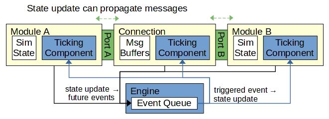
multi-GPU simulations [19]. The most basic simulated system, depicted in Figure 3.1, includes the
event engine, simulated modules, and a message connection.
Figure 3.1: High-level Akita component topology.
Each event corresponds to a state update at a specified time, in a single component. The
event engine drives simulation by dispatching events according to the simulation time. Event
dispatching can be done sequentially, where events complete one at a time, or in parallel, where
events in the same time slot execute concurrently.
During event execution, a component can update its internal state, schedule new events to
be executed later, or send messages to other components through a port. The port delivers a message
to a connection, which is a simulation component responsible for relaying messages to the intended
destination component. Upon receiving a message, the destination component schedules a future
event or immediately updates its internal state. Simulation execution continues until the event queue
is exhausted of future events to execute.
3.2 Formal Methods for Security Evaluation
Coppelia [31] is a hardware security verification tool that analyzes design constraints at the
HDL level. The HDL implementation of a microarchitecture is translated to C++ using Verilator [44].
This translated code can be analyzed using symbolic execution, which identifies conditions that
violate design constraints. Coppelia will generate a series of instructions comprising the exploit that
violated a design constraint, which researchers can use to assess the microarchitecture’s security.
14CHAPTER 3. RELATED WORK
Coppelia aims to shorten the verification gap [45] by enabling exhaustive constraint verification
utilizing a common hardware description, originally not intended for that purpose.
Information flow tracking [46] combines each hardware signal with a trust bit that indicates
whether the signal’s origin is trusted. If one of the input signals to a gate is untrusted, the output
of that gate is also untrusted. Signal trust propagates through all gates in the data path. This is an
exhaustive approach to security that guarantees the trustworthiness of all data. But, this comes at the
cost of additional hardware logic which hinders chip utilization and performance. VeriSketch [33]
uses information flow tracking and program sketching [47] to automatically synthesize HDL modules
according to a set of security constraints. The information flow tracking signals are used only to
verify security constraints during module synthesis and are not present in the final implementation.
As such, VeriSketch hardware implementations do not suffer the same performance penalties as
information flow tracking implementations.
3.2.1 CheckMate
This section will discuss the collection of work culminating in CheckMate [32], a formal
tool for detecting transient execution attacks at the microarchitectural level. The first work in
this collection, PipeCheck [48], is a formal verification tool for evaluating memory consistency
model implementations at the microarchitectural level. This functionality requires the adaptation of
happens-before graphs, from architectural-level description to microarchitectural-level description.
A microarchitecture happens-before graph, shown in Figure 3.2, represents instruction
execution as a set of nodes. Each node is a pair consisting of an instruction and an execution event
which the instruction is completing. The graph is organized by columns of instructions, where the
program order executes from left to right, and rows of execution events, temporally ordered from top
to bottom. The directed graph edges describe inter-instruction and intra-instruction happens-before
relationships, where the source node occurs before the destination node.
The user describes the temporal relationships of a happens-before graph as a set of first-
order relational constraints. In the case of PipeCheck, the user specifies constraints for the ISA’s
memory consistency model and for all instructions’ valid traversal through the data path. The SAT
solving engine can enumerate all possible executions for a combination of instructions and ensure that
no possible execution violates the constraints of the ISA. Subsequent work [49, 50, 51, 52] extends
this functionality to verify cache coherence models and memory operation ordering by software.
CheckMate [32] applies the same formal verification methods to side-channel attack
15CHAPTER 3. RELATED WORK
Instruction 1 Instruction 2
Event A Event A
Event B Event B
Event C Event C
Figure 3.2: A generalized happens-before graph depicting two instructions traversing three stages in
a microarchitecture.
analysis. It provides a similar user interface to PipeCheck and asks the user to describe valid
instruction traversal and an exploit execution pattern as a set of model constraints. Like in PipeCheck,
the SAT solving engine enumerates all possible execution sequences and searches each sequence for
the exploit pattern. By finding the exploit pattern within a candidate execution sequence, the tool
indicates that the microarchitecture is vulnerable to the exploit.
CheckMate will produce a security litmus test which is the sequence of instructions that
should induce the vulnerability on hardware. The work presenting CheckMate lists several exploits
to which a five-stage out-of-order pipeline is vulnerable, including Spectre, Meltdown, SpectrePrime,
and MeltdownPrime [53]. The SAT solver execution times for these exploits are shown to be tractable,
as the longest search required about 215 minutes to produce twelve litmus tests for Spectre.
3.3 Software Implementation Error Catching
Modern programming languages feature tools for mitigating implementation errors be-
fore software deployment. Such tools include runtime environments [54] or compile-time static
analysis [55] that reduce the responsibility of the programmer to manage dynamically allocated
memory. Memory management errors cause the majority of security vulnerabilities in some common
software [56].
Prior work has studied the implications of implementing a Unix-like kernel in the Go
16CHAPTER 3. RELATED WORK
programming language [54] and compared this implementation to the Linux kernel, written in the
C programming language [57]. Go provides a runtime environment that handles dynamic memory
operations. Researchers found that 40 security bugs in Linux do not exist in the Go implementation
for one of two reasons. Either the Go runtime environment would detect an out-of-bounds memory
access, resulting in a runtime error, or the automated garbage collector in the runtime environment
removes the possibility of use-after-free errors. Therefore, these security bugs could not be exploited
in the hypothetically deployed OS.
Static analysis is a common software practice for identifying implementation errors at
compile time [58, 55]. Extensible static analyzers allow users to implement checkers that enforce
custom design constraints, such as security [59].
The micro-kernel, seL4 [60], is an OS kernel designed and formally verified for information
flow security. The verification assumes the correctness of the host hardware and of the software
that facilitate the operation of the OS (e.g. compiler, boot loader). This highlights the importance
of verifiable secure hardware design, since insecure hardware may compromise the security of
higher-level applications.
17Chapter 4
Yori
This chapter presents the collection of tools developed to support Yori, our RISC-V
microarchitecture simulator. As with many simulator projects, development on these tools is ongoing.
This chapter focuses on the current state of the tools.
4.1 VEmu
VEmu [61] is a RISC-V functional emulator capable of ISA feature testing and binary
debugging. VEmu supports execution for 64-bit RISC-V binaries containing instructions from the
integer and multiply instruction groupings (known as RV64IM). As a functional emulation, VEmu
tracks and updates only architectural state, including 32 architectural registers, control status registers
(CSR), and memory.
VEmu provides user-mode emulation, where the guest program must assume it runs at
user-level hardware privilege. To support this, the emulator catches user-level interrupt instructions
and handles the OS functionality on the host system. This allows the emulator to catch the exit
Linux system calls and end program emulation.
VEmu leverages existing data structures developed for prior emulated memory implemen-
tations [62]. This is done as a development convenience and to facilitate planned simulation augmen-
tation features. Such features include simulation fast-forwarding [63] and check-pointing [63].
4.1.1 Verification and Performance
Emulator correctness is verified using the ISA unit tests implemented by the RISC-V
community [3]. Each unit test is a RISC-V binary workload that intends to stress test one instruction.
18CHAPTER 4. YORI
This is done by implementing code-blocks that execute the target instruction with typical operand
combinations and corner-case operand combinations. VEmu successfully executes the unit tests
for RV64IM instructions, which assumes physically addressed memory. Note, that VEmu does not
currently support the fence instruction.
The RISC-V community also provides RISC-V micro-benchmarks that can be used to
characterize VEmu [3]. One such benchmark, quicksort, is compiled for RV64IM and sorts 220
integers. This workload completes after retiring 325, 370, 695 instructions. On a host system
featuring an AMD Ryzen 5 3600 CPU and 16 GB of RAM, the quicksort completes in 61.8 seconds.
This yields an simulated execution speed of over 5.2 MIPS.
4.2 Microarchitecture Simulation
Transient execution side-channel attacks are the target vulnerability class for this research.
The reference microarchitecture that Yori implements must be susceptible to such attacks. As dis-
cussed in Chapter 2, SonicBOOM [14] implements performance features which enable transient
execution. This has allowed researchers to exploit Spectre vulnerabilities on simulated SonicBOOM
hardware [64]. Note that this research utilized a predecessor microarchitectural design to Sonic-
BOOM. This prior work, the public documentation [24], and open-source HDL implementation [65]
make SonicBOOM a suitable target for Yori and provide the information needed to implement a
simulated model of the microarchitecture.
SonicBOOM allows users to configure microarchitectural parameters when synthesizing
the HDL. Yori targets the provided SmallBoomConfig [13] configuration. This configuration
prescribes a scalar pipeline, in which a single instruction per cycle traverses a pipeline stage. This
configuration also limits the size of hardware data structures to account for scalar execution.
Yori uses the Akita framework [19] to drive simulation. Prior work has shown Akita to be
performant and scalable for multi-GPU simulations [19]. Akita’s event-driven execution provides a
logical interface to security verification. This will be discussed further in Section 4.3. Yori’s current
SonicBOOM implementation in the Akita framework is depicted in Figure 4.1.
Yori implements the microarchitecture in three simulated components, including the
Instruction Fetch Unit (IFU), the Memory Unit, and the Execution Backend. Note that work to this
point has focused on a detailed implementation of the Execution Backend. The pipeline stages
comprising that component facilitate out-of-order execution and, therefore, transient execution.
The IFU and Memory Unit are currently abstract models of the reference systems in SonicBOOM.
19CHAPTER 4. YORI
Figure 4.1: A high-level view of Yori’s simulation components.
Structural features, and the communications between components, are presented in the following
sections.
4.2.1 Instruction Fetch Unit
The IFU is responsible for dispatching instruction packets to the execution backend.
An instruction packet contains sequential instructions, in fetch order, and their corresponding
microarchitectural control signals. As Yori implements a scalar microarchitecture, one instruction
packet contains one instruction. The microarchitectural control signals are assigned by pipeline
stages to inform execution decisions made by succeeding stages.
As an abstract model, the Yori IFU facilitates a subset of the functionality provided by
SonicBOOM’s IFU. The Yori IFU manages the program counter (PC) and the instruction cache
(ICache). The PC is a single memory address that corresponds to the address of the next instruction
to be dispatched by the IFU. The ICache is a 4-way set-associative cache.
Each cycle, the IFU attempts to dispatch a new instruction packet corresponding to the
current PC. It first polls the ICache for the desired instruction. Each instruction in the ICache is a
32-bit value, in which architectural information for execution is encoded. The bit encoding for each
instruction is prescribed by the ISA.
If the instruction is available in the ICache, the IFU generates a new instruction packet,
assigns the instruction to the packet, and dispatches the packet to the Execution Backend. Otherwise,
the IFU generates a read request for the Memory Unit, which will deliver a cache line of instructions,
beginning at the requested PC, at a later cycle. Upon receiving the read response from the Memory
Unit, the IFU can dispatch the instruction packet corresponding to the PC.
The IFU may encounter back-pressure from the Execution Unit, where a succeeding
20CHAPTER 4. YORI
pipeline stage cannot complete an operation at the expected cycle. Thus, instruction packets cannot
continue to flow through the pipeline stages. This causes the IFU to stall until back-pressure is
relieved.
The IFU may also receive branch resolution updates from the Execution Backend which
will set the PC to an address on a new instruction path. The IFU will then dispatch instructions from
the new PC.
As an abstract model, the Yori IFU implements a subset of the features and data structures
employed by the SonicBOOM IFU. Importantly, the Yori IFU does not currently implement branch
prediction and instead assumes that the branch is not-taken. This results in a large performance
penalty to workload execution.
4.2.2 Memory Unit
The Memory Unit is responsible for facilitating memory read and write operations on
architecturally-visible memory. The abstract model is implemented by previous work [62]. The
Memory Unit may receive requests from the IFU or from the Execution Backend. It responds to
memory requests in one cycle.
4.2.3 Execution Backend Overview
The Execution Backend Akita component is comprised of several pipeline stages. Each
stage is implemented as an independent sub-module of the Akita component. During execution, an
instruction traverses all stages in an instruction packet. The order of pipeline traversal is Decode,
Rename, ROB, Issue, Register-Read, and Execute. A pipeline stage may stall upon reaching a hazard
during execution. This will cause back-pressure on the instruction traversal path, which may cause
preceding stages to also stall.
In addition to forward instruction traversal, Figure 4.2 highlights the additional communi-
cation between stages. The ROB and Execute stages must broadcast messages upon reaching a state
that requires microarchitectural state roll-back. Here, microarchitectural roll-back includes pipeline
flushing. The Execute stage also broadcasts the availability of stage-local hardware resources to
ensure the preceding stages dispatch instructions during the correct cycle. These communication
paths are necessary to ensure valid execution, but lead to software challenges that are discussed
further in Section 4.3. The following sections describe the Execution Backend stages in greater
detail.
21CHAPTER 4. YORI
Progress back-pressure
Decode Rename ROB Issue Reg-Read
Forward-progress
Roll-back μarch state
Broadcast availability Execute
Figure 4.2: Communication flow between stages in the Execution Backend.
4.2.4 Decode
Upon receiving an instruction packet from the IFU, the Decode stage extracts architectural
information from the 32-bit instruction and assigns additional microarchitectural control signals to
the instruction packet. Such architectural information includes logical (architectural) register indices
and static immediate data values. The microarchitectural control signals, referenced here, may be
used by later pipeline stages to guide execution.
Microarchitectural control signals of note include the branch mask and branch tag. The
Decode stage assigns each unresolved in-flight conditional branch instruction a unique one-hot
encoded branch tag. The Decode stage accumulates the current branch tags in a stage-local branch
mask. In essence, the branch mask enumerates all branch instructions leading to the current instruction
path.
The Decode stage assigns the current branch mask to each instruction it processes. This
allows succeeding stages to flush the instruction if a branch in the branch mask is resolved as
mispredicted.
4.2.5 Register-rename
The Register-rename stage manages the mapping between logical and physical registers.
Physical registers are microarchitectural registers that the pipeline uses in place of the architectural
registers. The Register-rename stage allocates physical registers to mitigate data hazards. Physical
registers are stored in the Register-read stage. The functionality of this stage is facilitated by three
hardware data structures. An instruction packet traverses the structures in the following order.
22CHAPTER 4. YORI
1. Map-table - This structure tracks the current physical register to which each logical register
corresponds. To each processed instruction packet, the Map-table adds the physical register
indices corresponding to the logical register operands. The Map-table also attaches the stale
physical destination register index, which is the current register mapping for the instruction’s
destination register. This stale physical destination register was allocated to the last instruction
that wrote to the same logical register.
2. Free-list - This structure tracks the allocation state of all physical registers. Here, allocation
state refers to the state of being allocated or unallocated. An allocated physical register
corresponds to a logical register, while an unallocated physical register corresponds to no
valid logical register. For each instruction, the Free-list allocates a physical register for the
instruction’s logical destination register. The Free-list marks the physical register as allocated
and attaches the register index to the instruction packet. Note that the instruction packet
now contains a physical destination register index that is different from the stale destination
register index. This assignment scheme avoids write-after-read (WAR) and write-after-write
(WAW) [2] data dependencies between subsequent instructions. The Map-table is updated
each cycle to reflect the register allocation. When the ROB notifies the Register-rename stage
of a newly-committed instruction, the Free-list deallocates the corresponding stale physical
destination register.
3. Busy-table - A physical register is considered busy until the instruction writing to that register is
completed by the Execute stage. The Busy-table tracks the busy state of each physical register.
When processing an instruction, the Busy-table marks the destination register allocated by the
Free-list as busy and attaches the busy state for the instruction’s operands to the instruction
packet.
When the ROB attempts to commit an instruction that results in an exception, it triggers
rename state unwinding [24] in the Register-rename stage. In state unwinding, the state of the
Map-table and Free-list are undone, one instruction at a time, in reverse Fetch order. Through this
process, the Register-rename stage reverts to a state which has only been modified by committed
instructions. From this state, the pipeline can successfully re-execute the instruction that encountered
an exception.
23CHAPTER 4. YORI
4.2.6 Reorder-Buffer
The ROB preserves the Fetch order of instructions, as delivered by the Rename-stage. The
data structure facilitating this functionality is a queue. Each queue slot stores the instruction packet,
its busy state, and its exception state. Once the instruction is stored, the ROB delivers the instruction
packet to the Issue stage.
When the Execute stage completes an instruction, the ROB is notified and marks the
instruction as not-busy. The ROB will commit an instruction when it reaches the queue head and is
marked as not-busy. This dequeues the instruction from the ROB. By reaching the queue head, the
instruction is the oldest instruction in the ROB. Therefore, by only committing the head of the ROB,
the queue preserves program order.
If the ROB tries to commit an instruction which generates an exception, the pipeline is
flushed and the Register-rename state is unwound. Execution is then restarted, beginning with the
instruction generating the exception.
4.2.7 Issue
The Issue stage buffers instructions in a priority queue before being dispatched to the
Register-read stage. An instruction can be dispatched once two conditions are met. The instruction
operands must not be busy, as dictated by the Busy-table of the Register-rename stage. This state is
updated in the Issue stage upon instruction completion by the Execute stage.
The second condition to be met before instruction dispatch is that the Execute stage must
have the hardware resources available to accept the instruction. The Execute stage broadcasts its
hardware availability to the Issue stage to facilitate the checking of this condition.
Once these conditions are met, the Issue stage can dispatch the instruction. The Issue stage
tries to dispatch instructions in program order by dispatching the oldest instruction in the queue that
meets the conditions. This can cause the Issue stage to dispatch instructions in non-program order in
cases when a younger instruction satisfies the conditions before the oldest instruction.
4.2.8 Register-read
The Register-read stage contains the physical register file (PRF), comprised of the microar-
chitectural physical registers. An instruction reads its register operands from the PRF to be processed
in the Execute stage.
Instructions completed by the Execute stage write operation results to the PRF.
24You can also read