USER MANUAL The CM2 CM2 User Manual: Contents
←
→
Page content transcription
If your browser does not render page correctly, please read the page content below
CM2 User Manual: Contents

USER
MANUAL
The CM2
SIDESCAN
SONAR
SYSTEM

Version 4.0 (2014)          i
CM2 User Manual: Contents

CONTENTS

Please note that this manual does not describe systems using MaxPro software, nor those using the C-Case
deck units. For those systems please refer to earlier versions of the manual. In case of difficulty contact
C-MAX Ltd or their local representative.

1. Summary of Warnings                …………        1

2. System Components                  …………        2
      Towfish
      Sonar Transceiver (STR)
      Tow Cables
      Accessories
      Specifications

3. Installing the System                 …………     4
       Data Acquisition Subsystem
       Tow Cable
       Installing a Winch and Pulley (if used)
       Securing the "soft" Tow Cable (if used)
       Attaching the Towfish
       Checking System Operation
       Spares and Tools

4. Planning the Survey                …………        12
      Survey Plan
      Line Spacing
      Line Direction

5. Operating the Towfish              …………        14
     Pre-launch Check
     Launch
     Bottom Tracking
     Bottom Tracking Controls
     Flying the Towfish
     Action if the Towfish Fouls
     Recovering the Towfish

6. Operating Guidelines               …………        18

7. Notes for the Helmsman             …………        19
      Navigation
      Steering
      Emergency Actions

8. Towfish Commands                …………           20
      Towfish Command Set
      Bottom-tracking, Up and Down
      Mute, On or Off
      Shallow Mode, On or Off
      Gain Hold, On or Off

continued ...

Version 4.0 (2014)                                 ii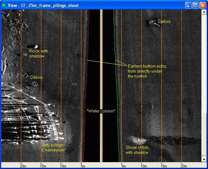
CM2 User Manual: Contents

9. Interpreting the Sonar Image     …………          21
       Checking Imaging Performance
       Water Column and Bottom Image
       Highlights and Shadows
       Image Corrections
       Causes of Image Defects

10. Routine Maintenance             …………          24
      Routine Maintenance
      Replacing the Towfish Breakaway Washer

11. Storage and Transit              …………         25

12. Repair and Replacement            …………        26
      Replacing the Towfish PCB
      Replacing a Transducer
      Repairing the Tow Cable
      Replacing the Safety Lanyard
      Servicing the Surface Electronics
      Servicing the STR

13. Troubleshooting                  …………         29

14. Interfaces                       …………          31
       Towfish/Tow Cable Interface
       STR Interface
       C-Shell, Winch and Counting Pulley Interfaces

15. Specifications                   …………         32
      Standard Towfish
      STR
      Tow Cables

(Sections 16-24 cover optional towfish, accessories and sensors)

16. DeepTow Towfish                  …………       34
      Introduction
      Attaching the Fins
      Looping the Fins together
      Attaching the Tow Cable
      Adjusting the Transducer Depression Angle
      Accessing the Internal Components
      DeepTow Specifications

17. C-Shell Enclosure                …………         39
      Introduction
      C-Shell Interface
      C-Shell Specifications

continued ...

Version 4.0 (2014)                                 iii
CM2 User Manual: Contents
18. CM2-WIN-300 Winch ………… 41
Introduction
Installing the Winch
Overload Clutch
Soft Start
Temperature Alarm
Signal Cable
Control Pendant
Winch Specifications
Replacing the Tow Cable
Accessing the Winch Drive Components
19. SK172 Winches ………… 47
Freeing the Drum in and Emergency
Replacing the Tow Cable
20. Wing Depressor ………… 49
Introduction
Fitting the Wing and Tail to the Towfish
Launching the Towfish and Wing
Towing the Towfish when Wing is fitted
21. Pulleys and Counting Pulleys ………… 51
Pulley Types
Cable Guides
Counting Pulley
Installing the Counting Pulley
22. Polemount Bracket ………… 53
Introduction
Fitting the Polemount Bracket
23. USBL Transponder Bracket ………… 54
Introduction
Fitting the Bracket, Early Type
Fitting the Bracket, Later Type
24. Towfish Sensors ………… 55
Heading Sensor
Depth Sensor
25. Additional Capabilities ………… 57
Towing a Magnetometer
ROV and AUV Configurations
26. Warranty ………… 58
Scope
Limitations
Fault Reporting
Returns
Transferability
Version 4.0 (2014) ivCM2 User Manual: Contents (This page intentionally blank) Version 4.0 (2014) v
CM2 User Manual: 2. System Components

1. SUMMARY OF WARNINGS

The warnings summarised here are intended to prevent injury to personnel and damage to equipment in
what can be a hazardous environment.

OPERATORS OF THIS EQUIPMENT ARE RESPONSIBLE FOR THEIR
OWN SAFETY

THE SUPPLIER ACCEPTS NO LIABILITY FOR THE CONSEQUENCES OF
EQUIPMENT USE OVER WHICH IT HAS NO CONTROL

DO NOT ALLOW THE TOWFISH TO STRIKE THE BOTTOM OR
OBSTRUCTIONS; THE TOWFISH SINKS WHEN THE BOAT TURNS OR
SLOWS

USE GLOVES TO HANDLE ALL STEEL-ARMOURED TOW CABLES

NEVER ALLOW SLACK IN THE CABLE WHILST THE TOWFISH IS
DEPLOYED

DO NOT EXPOSE THE TRANSDUCERS TO HEAT FROM STRONG
SUNLIGHT

ENSURE THAT ALL ELECTRONIC UNITS ARE DRY BEFORE STORAGE

Version 4.0 (2014)                           1
CM2 User Manual: 2. System Components

2. SYSTEM COMPONENTS

Towfish
The towfish is the acoustic sensor head. It transmits a very high frequency acoustic pulse (“ping”) at regular
intervals and receives the series of echoes that result from each ping.

                               Standard Towfish and Tow Cable Terminator

Two types of CM2 standard towfish are available, namely EDF (325/780kHz) and DF (325/100kHz). Both are
identical externally. These are digital towfish, communicating with the surface electronics via the tow cable.

The optional wing depressor for the standard towfish is described in Section 19.

The alternative DeepTow towfish and its cable terminator are described in Section 16.

Optional additional sensors for both standard and DeepTow towfish are described in Section 23.

Version 4.0 (2014)                               2
CM2 User Manual: 2. System Components
Sonar Transceiver (STR)
The “top end” (i.e. surface electronics) unit provides power for the towfish via the tow cable, receives the
echo data and other information such as the towfish altitude, and sends commands to the towfish. The
primary type of top end unit for the CM2 system is the Sonar Transceiver (or STR). As well as
communicating with the towfish, the STR communicates with the PC that acquires, records and displays the
sonar image. Communication with the PC is via the STR’s USB interface.
Sonar Transceiver (STR) Versions
There are two types of connectors used on STR's, either BNC or MIL-C-5015 connectors. Early units fitted
with a BNC connectors accept supply voltages in the range 10-18VDC; 24VDC was an ordering option. All
units fitted with MIL-C-5015 connectors and all later BNC units accept 10-28VDC as standard.
Early STR units also featured an analog output, generated from the internal digital signal, for driving “legacy”
acquisition systems and thermal printers.
Tow Cables
The CM2 tow cables use a single pair of electrical conductors to carry both data and power. There are two
types of tow cable offered as standard with the CM2. “Soft” cable (CX8) is intended for shallow work, where
the cable can be hauled and veered manually. The alternative standard cable (SS5) is 4.7mm diameter
stainless-steel-armoured cable intended to be handled by a winch. Various other diameters of steel-
armoured cable are available to special order.
Accessories
Optional accessories including the C-Shell, winches, towfish wing depressor, counting pulleys, polemount
bracket and USBL bracket, are described in Sections 17-24.
Specifications
Specifications for the major components and certain accessories are listed in Section 15.
Version 4.0 (2014) 3CM2 User Manual: 3. Installing the System
3. INSTALLING THE SYSTEM
Data Acquisition Subsystem
The CM2 system uses a PC, running Microsoft Windows, to acquire and display the sonar records. The user
normally supplies this PC. To install the acquisition software on this PC please refer to the MaxView
Installation Guide available from C-MAX or the local supplier. For third-party acquisition software refer to the
supplier's manual.
Link the Sonar Transceiver (STR), or C-Shell with its internal STR, to the acquisition PC via the USB cable
supplied.
Prepare to apply dc power to the STR. If powering from an AC supply, use the 60W power brick supplied with
the STR.
CAUTION: DO NOT SUPPLY THE STR FROM THE SAME DC SOURCE AS IS USED TO SUPPLY THE
WINCH. The voltage spikes generated when the winch is switched on and off can exceed allowed upper
voltage limit of the supply to the STR.
System with Optional Winch and Counting Pulley
Version 4.0 (2014) 4CM2 User Manual: 3. Installing the System
Connect the tow cable or winch signal cable (or “deck” cable) to the STR.
Connect a navigation data cable to the PC if required. As GPS and other sources of navigation data often
output via an RS232 serial connection, and as serial ports are becoming less common on PCs, this
connection may require the use of a serial-to-USB converter. Note that if a CM2 C-Shell (fitted with an STR)
is being used, the GPS data from the C-Shell’s optional internal GPS receiver is already mixed with the
sonar data on the C-Shell’s USB output.
If a counting pulley is to be used, connect its cable to the PC. This may also require a serial-to-USB
converter.
Tow Cable
Tut adhesive tape markers on the tow cable, a few metres above the terminator, to warn when the towfish is
close to the vessel.
Installing a Winch and Pulley (if used)
The tow cable should run directly from the top of the winch drum to a suitable pulley or fairlead.
Any pulley or fairlead must be no smaller than the cable’s recommended minimum radius, preferably
considerably larger. A pulley is better than a rigid fairlead.
The pulley should normally be suspended above the stern or stern quarter, able to move freely in any
direction, and positioned so that neither the towfish nor the tow cable is in danger of fouling the vessel's
propeller or rudder or any other structure. A central position minimises tow cable heave caused by the
vessel's roll, but may be too close to the propeller wash.
The winch should be mounted as far forward (away from the pulley) as practical, to reduce the maximum off-
axis angle of the cable. The path the cable from the pulley to the centre of the winch drum should be parallel
to the centreline of the vessel so as to minimize the tilting of the pulley and side force on the pulley rim when
the towfish is astern. The winch mounting must be able to withstand the shock of the towfish striking the
bottom.
The mounting “footprint” of the CM2-WIN-300 winch is shown in Section 19.
Securing a “soft” Tow Cable (if used)
Make sure that enough cable is flaked out on the deck so that the towfish can reach its operating depth
without the need to disconnect the inboard end of the tow cable. Provide a method of securing the tow cable.
A recommended method is to use a loop of 5-6mm diameter rope, one end secured to the deck and the other
terminated in a “prusik” knot with 2 or 3 turns around the tow cable. The cable will slip through the hitch until
the operator starts to tighten its grip.
Securing a Soft Tow Cable with a Prusik Knot
Version 4.0 (2014) 5CM2 User Manual: 3. Installing the System To prolong the life of the cable, avoid sharp bends, twisted loops, and shock loads. Attaching the Towfish Straighten out the end of the tow cable and, if it is a steel-armoured cable, ensure that there is no more than a half-turn of inherent twist in it. The following description applies to the standard CM2 towfish. The attachment of the DeepTow towfish is described in Section 16. First remove the drop-nose pin from the rear of the keel, feed the loop of the safety lanyard into the end of the keel, and replace the pin to secure the loop. Drop the nose of the pin, to 90 degrees, to ensure that the pin cannot fall out. Remove the dust cap from the tow cable underwater connector. Engage the tow cable socket on to the plug on the rear of the towfish, being careful to align the connector correctly. It is good practice to keep this plug clean and occasionally apply silicone spray to the pins. Note that if silicone grease (as provided with earlier spares kits) is used it must be applied very sparingly. Excessive grease can stop the towfish working. Attach the towing bail using the breakaway “safety” washer, and the M6 cap screw with captive washer. Use the 5mm hex key provided to tighten this screw. The breakaway washer is designed to fracture under excessive load. Version 4.0 (2014) 6
CM2 User Manual: 3. Installing the System

                       Attaching the Safety Lanyard and Tow Cable Extension

Version 4.0 (2014)                             7
CM2 User Manual: 3. Installing the System
Attaching the Towing Bail (Earlier Tow Cables)
On earlier tow cables the lefthand yoke has two holes through which a cable tie can be passed. On these
earlier tow cables the safety lanyard and the tow cable extension should be secured to yoke with a 3.5mm
cable tie so that there is no slack in the lanyard and in the tow cable extension between the yoke and the
rear fin.
Version 4.0 (2014) 8CM2 User Manual: 3. Installing the System
Attaching the Towing Bail (Interim Version Tow Cables)
On later tow cables the lefthand yoke has a raised hoop, as shown in the illustration. In an interim version of
the tow cable a stainless steel split ring was fitted to this hoop. On these tow cables both the safety lanyard
and the tow cable extension should be passed through this split ring. (Some cables were originally supplied
with the later type of yoke but with a cable tie rather than split ring.)
The current, upgraded version of the tow cable features a separately removable tow cable extension, to
which the safety lanyard is permanently secured. This configuration has several advantages, the most
important being that if the tow cable extension or its 3-way connector is damaged it can be easily replaced
without the main tow cable needing to be re-terminated. The terminator now includes a 2-way connector from
which the tow cable extension is only disconnected when, or if, a new extension needs to be fitted.
Version 4.0 (2014) 9CM2 User Manual: 3. Installing the System
Attaching the Towing Bail (Later Version Tow Cables)
Checking system operation
With the whole system now connected as described earlier in this Section, apply power to the STR or C-
Shell. The red Power indicator should light.
If MaxView has been installed, open it and select Start... from the Towfish menu. Alternatively press the
spacebar then select Start Towfish from the Quick Select menu. If some other acquisition software is
installed instead of MaxView, the towfish can be started using that software.
When the towfish is commanded to start, the green Trigger indicator on the STR should light continuously
whilst the Start Towfish dialog displays the Energizing… message. This message should be automatically
replaced after a short period by Connecting…
The Energizing… message indicates that a voltage of approximately 40VDC* is being supplied to the tow
cable connector. This voltage is passed to the towfish to charge its internal capacitors and start its operation.
The Connecting… message indicates that the towfish has started its initialisation and that the tow cable
telemetry is being set up. This message should disappear when the telemetry link has been established and
the towfish has started running.
Version 4.0 (2014) 10CM2 User Manual: 3. Installing the System Note that initially the towfish runs silently, i.e. in the muted mode. This is to allow the telemetry link to complete its optimisation without any interference from the transducer drive voltage. The muted period lasts for the first 80 pings. As soon as the towfish runs the STR Trigger LED indicator flashes, once per ping. Wait for the gain, the amplification of the echo image, to rise to a point where the “waterfall” display on the screen has filled in to show “noise” from the environment. At this point the operation of the towfish can be given a basic bench check known as a “rub test”. Without touching the metal of the towfish with either hand, place one hand briefly on the face of one of the transducers. This should result in an increase in signal on the appropriate side of the waterfall display for the time that the hand is that position; at least until the automatic gain control reduces the signal. Then test the other side in the same way. The Quick Select menu, accessed by pressing the spacebar, can be used to change the sonar range and frequency or to stop the towfish. The spacebar can also be used to clear the Quick Select menu. (*This voltage level depends on whether a towfish is connected at the time that it is measured. Also, after the towfish has started pinging, if the tow cable is higher in resistance than a certain value, the towfish will detect that its internal voltage has dropped below nominal. In this case it will command the STR to increase its supply to the tow cable by a further 24V.) Spares and Tools Always carry spare breakaway washers. Note that two types are available, the original 1.4mm thick type for the standard towfish and the 2.2mm thick type specifically for the DeepTow. The stainless steel 5mm hex key provided with the system spares is the only tool required in normal operation. Every towfish is supplied with a kit (CM2-TSK) containing minor spares and consumables. Version 4.0 (2014) 11
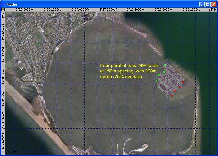
CM2 User Manual: 4. Planning the Survey

4. PLANNING THE SURVEY

Survey Plan
Every survey or search needs to be planned in advance. Survey planning and post-processing are topics
that are wider than can be covered here. Most sonar acquisition software packages, including MaxView,
include the facility to plan survey lines for guiding the helmsman.

Line Spacing
The frequency and range settings should be defined for the type of task being planned, whether it is a search
for a wreck or lost anchor, or a post-dredge clearance check, for example.

The image quality is reduced in the region below the towfish because the geometry results in a compressed
image in this zone; also the steep angle results in poorer shadow information. The quality is also reduced at
the extremity of the range primarily because of beam spreading. Survey lines should therefore be spaced
with sufficient overlap (e.g. 75m when working with 100m range setting) to ensure complete coverage.
Overlap is also necessary to compensate for course deviations.

Line Direction
It is normally preferable to run survey lines in the same direction as any current. Where currents are very
strong the lines may need to be run in only one direction, against the stream, as running with the stream
would give too high a speed over the ground thereby reducing the number of pings on any target.

                           Typical Small Survey; Area Sweep inside a Harbour

Version 4.0 (2014)                                   12
CM2 User Manual: 4. Planning the Survey In order to identify a target, or to provide extra assurance of coverage, it may also be necessary to follow the along-current lines with a set of perpendicular, cross-current, lines. Sometimes the major consideration in planning lines is not the direction of the current but the bathymetry. It is easier to survey along lines of approximately constant depth rather than to be constantly heaving and veering tow cable to keep the towfish at a suitable altitude. Finally, the wind direction may be the controlling factor. Waves running across, rather than in the same direction as, the survey line will cause a spiralling movement of the tow cable and oscillation of the towfish track. This will have more of an effect on the image than the simple pitching motion if the ship is running into, or directly away from, the waves. Version 4.0 (2014) 13
CM2 User Manual: 5. Operating the Towfish

5. OPERATING THE TOWFISH

Pre-launch Check
Check that the towfish transducers are angled high or low, as required, as indicated by the yellow dots on the
depression adjuster cam.

                     Adjusting the Transducer Depression Angle (Standard Towfish)

Check that the tow cable connector is firmly home, and that the bail is correctly attached to the towfish.

Version 4.0 (2014)                                    14
CM2 User Manual: 5. Operating the Towfish
Check that the tow cable is clear and free from twists, and that the winch, if present, is powered and ready
to run.
Note that the automatic gain adjustment starts as soon as the towfish is switched on.
Launch
Set the display to show the water column (i.e not slant-range-corrected). Launch the towfish astern with the
vessel preferably at slow speed, then lower it to an altitude above the bottom within 5-15m initially
CAUTION: DO NOT ALLOW ANY SLACK IN A WINCHED TOW CABLE - a slack cable can start to wind
outside the winch drum and can also form loops that can pull tight and seriously damage the cable.
The "soft" tow cable can be handled without gloves but is still capable of giving friction burns if allowed to
slip.
If the optional wing depressor is used, refer to Section 20 for advice and important warnings.
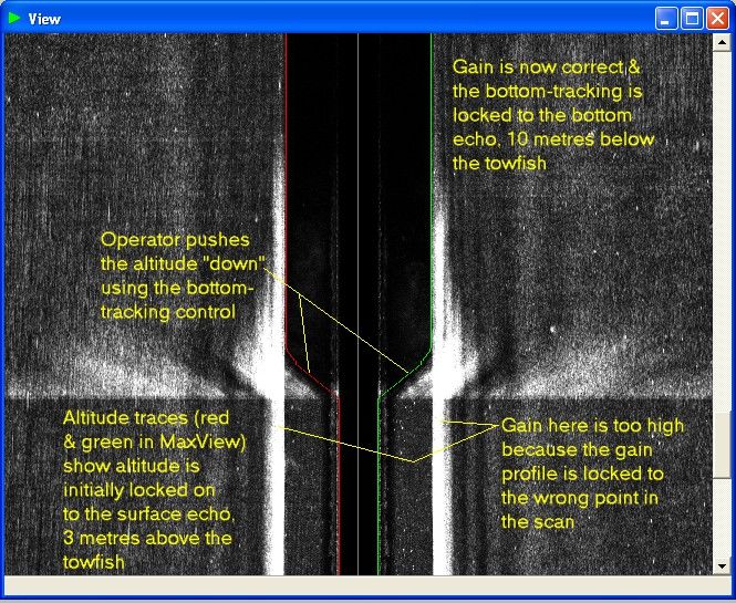
Bottom Tracking
The indicated altitude is shown in MaxView’s sonar parameters, or the equivalent in other versions of
acquisition software.
The indicated altitude may be marked on the display by a pair of lines overlying the initial bottom echoes. In
MaxView these lines are red and green; see the illustration below.
CAUTION: VERY IMPORTANT: IF THE INDICATED ALTITUDE DIFFERS FROM THE TRUE ALTITUDE
THE OPERATOR MUST TAKE ACTION TO PUSH THE BOTTOM-TRACKING INTO LOCK.
Locking the Bottom-Tracking after Launch
With earlier versions of the towfish, when the towfish is first launched the bottom-tracking may lock on to the
surface echo or may stay in a “neutral” position. This will give the wrong indicated altitude.
Version 4.0 (2014) 15CM2 User Manual: 5. Operating the Towfish An example of the bottom-tracking initially locking on to the surface echo is shown in the illustration above, in the lower section of the image. The operator can see from the image that the towfish is actually deeper and uses the bottom-tracking controls to push the bottom-tracking into lock. Bottom Tracking Controls If the bottom tracking initially fails to lock on to the bottom correctly then use the bottom tracking control to push it into lock. In MaxView the hotkeys Ctrl + Up Arrow and Ctrl + Down Arrow can be used, or Bottom Tracking in the Towfish menu. All third-party acquisition software for the CM2 has equivalent bottom-tracking controls. Flying the Towfish As soon as the altimeter has locked to the bottom and the image is normal, wind the cable in or out, or adjust speed, until the towfish flies at an altitude equivalent to 8-10% of the range limit. Note that the indicated altitude cannot exceed 20m for 780kHz operation, 40m for 325kHz, and 60m for 100kHz. If the towfish is operated above these maximum altitudes, the image may be degraded; also the altimeter may try to lock on to surface echo instead of the bottom. Minimum indicated altitude is 1.4m. MaxView and other acquisition programs may sound an alarm if the altitude falls below a preset value. The towfish must be flown high enough to clear any obstacles. Over uneven ground, flying high increases safety and prevents excessive shadowing. Over flat and featureless ground, flying low enhances the shadows of any object that may be present. In shallow water it may be necessary to fly lower to stay below the wake. In very shallow water it may be better to deploy the towfish alongside, or at the bow, rather than astern, but keep the towfish and cable away from the propeller! Depending on speed and depth expect to pay out about 3 metres of tow cable for every metre of towfish depth (not altitude). Always keep a reserve of at least 3 turns of cable on the winch drum. See Notes for the Helmsman. Tow in the range 2.5 to 6kt (speed through the water; this may differ from speed over the ground or GPS- indicated speed). Low over-the-ground speeds give more scans per metre of travel and a correspondingly better image resolution. Sometimes, however, a higher speed will give a steadier course. CAUTION: THE TOWFISH WILL SINK CLOSER TO THE BOTTOM DURING TURNS AND WHENEVER TOWING SPEED REDUCES Action if the Towfish Fouls If the towfish hits the bottom or other obstruction, the increased towing force will usually break the breakaway washer. The safety lanyard will then apply tension to the rear of the towfish. This will normally cause it to tumble and to free itself of the obstruction. In the meantime the towing vessel should, of course, slow down but without going astern into the cable! Recover the towfish and replace the breakaway washer. Inspect the towfish and tow cable for any damage. Version 4.0 (2014) 16
CM2 User Manual: 2. System Components

Recovering the Towfish
Slow to 2 to 4 knots before the towfish hits the wake. Watch for the tape marker warning that the towfish is
close.

Wash the towfish, cable and winch with fresh water immediately after use in seawater. When the tow cable is
disconnected from the towfish, cap the cable connector to keep it clean.

CAUTION: DO NOT EXPOSE THE TRANSDUCERS TO HEAT FROM STRONG SUNLIGHT

Version 4.0 (2014)                               17
CM2 User Manual: 6. Operating Guidelines

6. OPERATING GUIDELINES

Do not allow the towfish to hit the bottom – be aware towfish sinks when turning!

Fly the towfish on as straight a course as possible, to prevent distortion and
smearing of the image

Fly the towfish lower (but safely clear of the bottom) to give best image shadows,
e.g. 5m altitude; fly it higher to give longest effective range, e.g. 10m altitude or
more, except in shallow water

Use the higher frequency for best image resolution, and for small targets; use the
lower frequency for longest effective range, and for big targets

Use 10deg transducer depression in normal circumstances; use 20deg depression
if the bottom image is being obscured by reflections from the sea surface

Higher tow speeds are OK for 100kHz operations, e.g. up to 6 knots

Use lower tow speed for 325kHz operations, e.g. 4 knots

Use lowest tow speed for 780kHz short-range operations, e.g. 3 knots

Low speed gives more “pings” on each target and gives greater towfish depth for
any particular tow cable length

High speed makes it easier to keep the towfish on a straight course

Overlap survey tracks to give best target detection probability; overlap by at least
2x altitude (approximate rule), ideally 100%

Orthogonal survey tracks (e.g. E-W then N-S) may give more information on target
shape

During the survey always watch the image in NORMAL geometry to check that the
bottom-tracking (automatic altitude measurement) is locked on to the bottom echo

If the bottom-tracking is not in lock then use the altimeter forcing buttons (up-down)
to restore the correct indicated altitude

Check the incoming nav data and don’t forget to RECORD the sonar data!

Version 4.0 (2014)                         18
CM2 User Manual: 7. Notes for the Helmsman

7. NOTES FOR THE HELMSMAN

Navigation
Use the sonar's plotter window to show waypoints, the track and the swept ground.

Steering
The quality of the sonar images depends on the skill of the helmsman. This applies especially to
the 780kHz and 325kHz operation.

The helmsman is so important because the towfish can only collect good images if it flies straight.
Because of this, steering a sidescan sonar survey is not the same as steering a conventional
sounding line.

A turning towfish stretches the image on one side and compresses the other, wasting the high
resolution of which the system is capable. (A high power telescope can only be effective if it is held
steady!) As well as corrupting the outer areas of the image, a turning towfish also upsets the
matching between the gain (image amplification) profile and the beam shape, causing alternate
light and dark patches in the inner areas of the image.

Use small, slow wheel movements even if this means that the vessel temporarily leaves the
planned survey line. If an autopilot is available it will, under most conditions, steer a better sonar
course than a human helmsman, even though the heading may need to be trimmed occasionally.

Remember that the towfish follows the stern, particularly when the tow cable is short, and is
therefore affected by rudder movements as well as by course deviations.

At the end of the survey line, the helmsman must warn the sonar operator before turning and must
not turn sharply, or the towfish could strike the bottom.

Emergency Actions
Emergency actions should be discussed in advance of the survey, between the sonar operator and
the helmsman. The planned actions will depend on the water depth and depth variation, bottom
type and the danger from obstacles.

If sharply rising ground or an obstacle is detected on the ship’s echo sounder it may be too late to
raise the towfish by hauling in the tow cable, particularly if the cable is several hundred metres
long. Here the quickest way to raise the towfish may be to increase the ship’s speed as quickly as
possible. Of course if, despite this manoeuvre, the towfish still strikes the obstacle or bottom the
impact will be at higher speed.

Slowing to avoid an impact with an obstacle will almost certainly drop the towfish on to the bottom,
but may reduce the risk of losing the towfish.

If the towfish gets entangled, and the ship is manoeuvring above, beware of catching the tow cable
in the propeller.

Version 4.0 (2014)                                19
CM2 User Manual: 8. Towfish Commands

8. TOWFISH COMMANDS

Towfish Command Set
The CM2 towfish uses the same set of commands regardless of what acquisition software is being used.

Towfish start, stop, range selection and bottom-tracking control must be supported by all acquisition
software; other commands may or may not be supported. MaxView offers short-cut keys for range selection
and bottom-tracking control, as well as for towfish start and stop.

Bottom-tracking, Up and Down
These allow the operator to force the indicated altitude to the correct value so that the altimeter can resume
lock on to the bottom.

Mute, Off or On
Mute allows the towfish to run as normal but with no acoustic transmissions. This is useful for diagnostic
purposes where an echo sounder or other acoustic source may be interfering with the image. When muted,
indicated altitude is zero.

Shallow Mode, Off or On
Shallow mode is intended for use only in very shallow water where the user needs to use the towfish at less
than the normal altitude limit of 1.4m. In shallow mode the gain profile is started at the towfish position itself
instead of at the first bottom echo and the indicated altitude is zero.

Gain Hold, Off or On
Gain Hold allow the automatic gain to be inhibited, fixing the profile of image amplification across the range
as it was when Gain Hold was selected.

Normally the only reason to disable the automatic gain is if the image of a certain target, such as a wreck,
needs to be observed without the gain slowly changing. If the gain profile is held whilst the target is in view,
the reflectivity of any part of the target can be directly compared. Also if the target has a significant dark area,
holding the gain constant avoids the “gain shadow” as the scan moves back on to the relatively light
background again.

CAUTION: On versions of the towfish up to and including V6, if the gain profile is held constant this
automatically disables the towfish from measuring its altitude. The reason for this is that changes in bottom
reflectivity together with the fixed gain may mean that the altimeter would have difficulty in bottom-tracking.
However the altitude can still be adjusted by the operator using the bottom-tracking, up and down controls.
Also note that the correction for the shape of the acoustic beams may be wrong if the altitude changes whilst
the gain is held.

Version 4.0 (2014)                                      20
CM2 User Manual: 9. Interpreting the Sonar Image

9. INTERPRETING THE SONAR IMAGE

(This topic may be covered in additional detail in help text associated with MaxView or with third-party
acquisition software.)

Checking Imaging Performance
CAUTION: INCORRECT SETTINGS WHEN USING THIRD-PARTY ACQUISITION SOFTWARE AR
ALMOST CERTAIN TO RESULT IN A DEGRADED IMAGE. IT IS ADVISABLE TO USE MAXVIEW TO
CHECK PERFORMACE.

Note that MaxView is free to download and to use to check that an optimum image is being obtained. The
paid-for acquisition dongle is only needed if the acquired data is to be recorded.

Water Column and Bottom Image
At the very centre of the image is a line that corresponds to the track of the towfish.

                                                Example Image

Version 4.0 (2014)                                     21
CM2 User Manual: 9. Interpreting the Sonar Image On both sides of the central line, the (normal geometry) picture is occupied by what is called the 'water column'. This represents the time before the echo first returns from the bottom directly below the towfish. The water column normally shows up as a white area. Occasionally, if the towfish is close to the water surface, faint echoes of the surface may show up in the water column. Wake bubbles, fish shoals, and other mid- water objects, may appear in the water column on one or both sides, depending on whether they are to one side of the towfish (but still nearer to the towfish than to the bottom) or are directly below the towfish. Note that this water column image does not represent a gap in coverage. The bottom echoes on either side of the water column are DIRECTLY BELOW the towfish, as can be seen when slant-range correction is applied. Highlights and Shadows Highlights, shown as darker points or smudges, indicate that the beam has struck a stronger echo reflector. Hard surfaces reflect more strongly; so do surfaces that face the beam direction. The air-filled swim bladders of fish can also act as good reflectors. The towfish sees most of the bottom in its view at quite a low angle, as little as 5º at the outer regions. This means that the sonar picture normally includes shadows as well as highlights. Shadows show up as lighter areas usually lying beyond a highlight or line of highlights. They can indicate the presence of an object and can also provide clues about its height and shape. If there are no associated highlights, the shadow may just indicate a depression in the bottom. If an object casts a shadow on a flat bottom the height of the object is given by simple geometry, using the shadow length, the towfish altitude, and the true (slant) distance of the object from the centreline. Some acquisition software, including MaxView, includes the ability to calculate the object height by running the cursor along the length of the shadow. Image Corrections For safety when gathering sonar records use the uncorrected, normal geometry image, not the slant-range corrected image. When reviewing the records, or when taking measurements, corrected geometry may be useful. Selecting slant-range corrected geometry (SRC) corrects for the 'slant range' distortion, by differentially stretching the image, and removing the water column. Over rocky or very uneven ground the closure at the centre of the SRC image may not be perfect. If the ground is uneven it cannot be assumed that the whole bottom is varying in unison, so a smoothed altitude value is used. The SRC process exaggerates any mis-closure. Although SRC geometry corrects for slant range distortion, it does not correct the display 'aspect ratio', i.e. ensure that a square area of the bottom is represented by a square on the display. To do this requires replicating or suppressing ping lines and is not generally desirable. Causes of Image Defects It is important that the towfish is towed on a steady track and without excessive heave motion transmitted down the tow cable. Any erratic motion of the towfish will transfer to the image. Roll oscillations may produce light and dark banding, alternating between left and right sides. Turning stretches the image on one side and compresses the other. Version 4.0 (2014) 22
CM2 User Manual: 9. Interpreting the Sonar Image

If the towfish is near the surface it may pick up reflections from the surface waves. This can reduce the
maximum range at which a good bottom image is obtained. Also in calm conditions, particularly in shallow
water, the echoes can reflect off the surface as well as returning directly. This 'multi-path' effect shows up in
the image as ghosting. The CM2 325kHz towfish has a sharper surface cut-off than most sidescan sonars
and is inherently more resistant to both the above effects.

The CM2 towfish transducers are adjustable in angle. In the normal position they are depressed nominally
10º from the horizontal. This angle gives maximum range. In the other position they are depressed
approximately 20º from the horizontal. This gives greater immunity from spurious echoes from the surface,
which may be useful in shallow water, but sometimes reduces effective range.

The wakes of motor vessels contain a vast number of microscopic bubbles, which may take ten minutes or
more to dissolve. Wakes left by other vessels can show up prominently on the sonar image and should not
be confused with permanent features.

Note that a large object, such as a wreck or a piling structure for example, may appear to be distorted if it tilts
towards the direction from which it is being viewed or extends above the altitude of the towfish.

Version 4.0 (2014)                                     23
CM2 User Manual: 10. Routine Maintenance

10. ROUTINE MAINTENANCE

Routine Maintenance
Maintenance is simple and is normally limited to the following tasks: -

(a) Immediately after use, thoroughly wash the towfish with fresh water if it has been exposed to seawater:
also wash the tow cable and winch

b) Daily, or whenever it is suspected that the breakaway washer attaching the bail to the towfish has been
stressed in use, inspect the washer; refer to the replacement procedure below

c) Periodically inspect the whole system, particularly the cable, for accidental or corrosion damage that might
otherwise go unnoticed

d) Clean the exterior of all items, when appropriate; for the STR or C-Shell use a cloth lightly damped with
fresh water, no solvents

e) Follow the winch maintenance instructions.

Replacing the Towfish Breakaway Washer

The breakaway washers supplied with CM2 towfish are manufactured from phenolic resin bonded fine-
weave fabric. They are designed to yield with consistent characteristics and should be replaced only with
approved spares.
The breakaway washers used by the standard and DeepTow towfish are nominally 1.4mm thick and 2.2mm
respectively. They should not be interchanged although two 1.4mm washers can be used in place of one
2.2mm washer in emergency.

The breakaway washer secures the tow cable bail assembly to the spigot on the towfish. It should be
replaced if the bail has pulled free or the washer shows signs of stress. Breakaway washers should be
inspected regularly.

Version 4.0 (2014)                                    24
CM2 User Manual: 11. Storage and Transit

11. STORAGE AND TRANSIT

CAUTION: KEEP THE TOWFISH TRANSDUCERS OUT OF DIECT SUNLIGHT TO PREVENT THEM
FROM BECOMING EXCESSIVELY HOT

The system should preferably be stored and transported in purpose-designed containers. Internally padded
shipping/storage cases can be supplied for all the system components.

On the optional CM2 or SK172 winches, tape or strap the tow cable to prevent it unreeling from the winch
drum.

Ensure that all equipment, particularly the STR, is dry before packing.

Keep the empty cases closed whilst the system is in use so that they do not accumulate condensation.

Version 4.0 (2014)                                   25
CM2 User Manual: 12. Repair and Replacement

12. REPAIR AND REPLACEMENT

Replacing the Towfish PCB
The following description applies primarily to the standard towfish although some applies also to the
DeepTow towfish as described in Section 16.

The towfish internally contains only lead ballast and a single main printed circuit board (PCB). This PCB can
be replaced as a unit by the user. Note that this PCB is complex and is not user-serviceable. Any attempted
repair of this PCB by the user will invalidate the warranty and may cause permanent damage.

The towfish should be opened and resealed only in low or moderate humidity conditions to avoid the
possibility of condensation forming internally when the towfish is immersed in cold water.

It is assumed that the tow cable and safety lanyard have been disconnected.

Dismantling the towfish is easier if someone is available to hold it in position, resting with its nose and keel
on a bench, with the keel held upright.

Set the transducer depression angle to 10º and temporarily put cable ties through the slots shown on the
illustration. This secures the transducers to the keel.

                                            Disassembled Towfish

Remove the two M6 button head screws, or M5 socket cap head screws on earlier units, at the forward end
of the keel. This is easier if the towfish tube is pressed down on the keel to keep pressure off the screws.

Push the tube forward and then disconnect the two transducer connectors. Completely separate the tube
assembly from the keel/transducer assembly. The rear bulkhead is now free to be extracted from the tube,
but it will be retained by the grip of the O-rings. Rotate the rear bulkhead to loosen this grip, pulling outwards
at the same time. If necessary use two large screwdrivers, with their blades in the recesses each side of the

Version 4.0 (2014)                                     26
CM2 User Manual: 12. Repair and Replacement rear bulkhead, to start the extraction process.Note that in cold conditions the rear bulkhead may be released more easily from the grip of the O-rings if the tube is heated near the joint, for example by pouring hot water over this area. Note also that if the rear bulkhead and the tube become misaligned (i.e. off axis) they may tend to jam together. CAUTION: WHEN SLIDING THE PCB AND BULKHEAD IN AND OUT OF THE TUBE DO NOT ALLOW THE BLACK HEATSINK TO SCRATCH THE SEALING SURFACE OF THE TUBE Whenever the rear bulkhead (or the nose) has been removed the end of the tube is vulnerable to damage. Even a short drop on to a hard surface may distort the bore. To remove the PCB, first disconnect all attached connectors. Then remove the locknut from the M4 stud in the rear bulkhead bracket that retains the PCB. On earlier units an M4 screw is used instead of a stud and locknut. CAUTION: WHEN REMOVING OR RE-ATTACHING THE PCB FROM THE REAR BULKHEAD BE CAREFUL NOT TO DAMAGE THE SMALL THERMOMETER CHIP ON THE UNDERSIDE OF THE PCB BY CATCHING IT ON THE BULKHEAD BRACKET Reassembly requires care. The two O-ring seals on the rear bulkhead may be renewed using standard nitrile rubber seals of 49.5mm inside diameter, section diameter 3.0mm, medium hardness (Shore Hardness A70). All the sealing surfaces must of course be clean and dry, and they should be very lightly lubricated with the silicone grease provided or with silicone spray. The replacement of the rear bulkhead O-rings, and cleaning, should be done with the PCB removed. Reassemble the tube assembly to the keel/transducer assembly by the reverse process. Finally rotate the transducers to the 10º depression angle (cam dots high) then remove both cable ties from the slots. There is normally no need remove the nose of the towfish but, if there is, proceed as follows. Unscrew the single M5 cap head screw at the base of the nose. Alternatively, on earlier units, the nose is retained by two screws, one each side of the nose; these should not be unscrewed but should be screwed clockwise fully inwards. This will release the nose but it will be retained by the grip of the O-rings. Rotate the nose to loosen this grip, pulling outwards at the same time. If necessary use two screwdrivers, with their blades in the recesses each side of the nose, to start the extraction process. Putting a rubber band round the nose may enable it to be gripped more easily. As the nose is replaced, rotate it to align the locking screws. Replace the M5 locking screw on the underside or, alternatively, on earlier units, wind each locking screw counter-clockwise outwards just enough to lock the nose in position. Use MINIMUM torque. Replacing a Transducer To replace one or both of the acoustic transducers, do not open the towfish tube, i.e. do not separate the rear bulkhead from the towfish tube. Remove the tube assembly as described in the previous section. Remove the two temporary cable ties and then lift out the pair of transducers, still hinged together with the hinge rod. Slide out the hinge rod. Be careful to retain the adjuster components on the rod. They must be grouped at the front (screw) end, with the screw head on the cam pointing forwards. The assembly order on the rod is the adjuster components (cam, coil spring, M5 washer) then the transducers.. Never remove the angled backplates from the transducers. Version 4.0 (2014) 27
CM2 User Manual: 12. Repair and Replacement

Replace the transducers by the reverse procedure, and refit the tube assembly as described earlier.

Repairing the Tow Cable
In the event that the “wet” end of the cable requires re-termination, this may be performed by the Factory.

Alternatively the cable may be re-terminated in the field using the termination kit, available as a standard
accessory.

Steel-armoured cables cannot normally be repaired mid-way along their length by splicing because the size
of such a splice would prevent the cable from layering properly. Manually handled “soft” tow cables can, in
an emergency, be spliced but it is difficult to ensure that the splice retains sufficient strength and such a
repair is not recommended.

If a steel-armoured cable is damaged close to the winch end and the damage is such that the cable is
unserviceable, then this damaged inboard section will need to be cut out. The shortened cable will then need
to be re-terminated on to the winch. In these circumstances, or if the cable is to be completely replaced,
consult Section 18 or 19 for guidance on removing and replacing a tow cable on the CM2-WIN-300 or SK172
winches. The guidance for these winches may also be applied, where appropriate, to larger winches.

On newer tow cables of either type, steel-armoured or soft, the tow cable extension is a separate item which,
if damaged, can be replaced without re-terminating the main cable. To replace this type of tow cable
extension first unscrew the locking collar around the tow cable extension where it attaches to the terminator.
When this collar is released remove the extension to reveal a 2-pole female waterproof connector. Fit the
new tow cable extension by the reverse process and tighten the collar.

Repairing the Safety Lanyard
In the latest design of tow cable the safety lanyard is permanently attached to the tow cable extension.
Replacement of either the extension or the lanyard should therefore normally be done by replacing the
complete unit.

For the earlier design of tow cable a damaged or worn lanyard can be replaced individually and should
normally be replaced with a factory-produced item to ensure that the dimensions are correct.

If a lanyard for a standard towfish must be constructed locally in emergency, it should have an internal
length, measured over 8mm pins, of 98.5cm.

Servicing the Surface Electronics
Some items are SENSITIVE TO ELECTROSTATIC DAMAGE and must be handled accordingly.

Be careful not to stress cables or connectors when disassembling equipment.

Before removing any component or internal cable, record carefully how it is secured, preferably using
photograhs, and replace it exactly as found.

Consult the local C-MAX representative or the factory for advice.

Servicing the STR
To gain access to the internal parts of the STR remove the three M3 screws at the lower rear of the unit and
carefully slide the chassis out.

Take care when replacing the chassis not to trap the LED leads between the chassis and the top of the
enclosure.

Version 4.0 (2014)                                    28
CM2 User Manual: 13. Troubleshooting

13. TROUBLESHOOTING

STR will not power up
Check the supply voltage.

Towfish will not start
Wait 30 seconds before trying again.

Check all connectors.

Use a DC voltmeter on pins 1 and 2 of the underwater tow cable connector (disconnected from the towfish)
to check that approximately 42V appears for a period when the towfish is commanded to start.

If an SK172 winch is present, inspect the slip rings within the winch and, if necessary, clean them.

Towfish altimeter locks on to the surface echo
This can only occur if the towfish is nearer to the surface (or the wake bubbles) than to the bottom while, at
the same time, the signal gain has not yet reduced to the correct value for the bottom echo.

Use the towfish bottom-tracking commands to force the indicated altitude to the correct value.

Image contrast poor at the longer ranges
Check that the transducer depression angle is set high (10º).

Check that the transducer faces are clean and free from oil or grease. Clean with mild detergent.

Try greater towfish altitude.

Check system performance in a known environment.

Image shows unexpected patterns on outer zones
If the sea surface is rough and the bottom is smooth then suspect interference from surface echoes. Try
setting the transducer depression angle to low (20º).

Image shows spots or other interference
Temporarily mute the towfish to aid diagnosis, and then try switching off echo sounders, pingers or other
sonars. Also try throttling back any outboard motors, particularly those with underwater exhaust.

Reduce tow speed.

Ensure that the towfish is below the wake.

Try reducing the towfish altitude.

Version 4.0 (2014)                                    29
CM2 User Manual: 13. Troubleshooting

Image shows alternating dark and light bands
If these bands are at 90º to the towfish track, it indicates that the towfish is not flying steadily.

Try to reduce the heave motion being transmitted down the tow cable. Hold a steady course and heading.

Try increasing towing speed so that the vessel holds a straighter course.

Image suddenly goes very erratic
The towfish has probably struck the bottom, or a mid-water obstacle such as an anchor chain, and broken
the breakaway washer. Recover the towfish carefully.

Winch does not operate
Check the supply voltage and polarity.

Check the operation of the remote control pendant using an ohmmeter between the COMMON and IN and
OUT contacts.

Other troubleshooting advice
If further advice is required, consult your local representative or the Factory.

Version 4.0 (2014)                                       30
CM2 User Manual: 14. Interfaces

14. INTERFACES

Towfish/Tow Cable Interface
Wet end interface
     Mechanical: CM2 terminator, bail arm assembly and tow cable extension
     Electrical: SubConn Micro 3 female (or equivalent); Micro 2 female upper connector on extension
     Data = pins 2 and 3, polarity not significant; balancing signal (in tow cable extension only) = pin 1

STR Interface
Tow cable or winch deck cable
      BNC or MIL-C-5015, size 10, threaded, 2-way bulkhead connector, polarity not significant
PC link
      USB type B socket; USB1.1 or 2.0
Power input
      2.5mm DC jack socket, central pin = +ve, or MIL-C-5015 size 14, threaded, 4-way bulkhead
      connector, Pin A = +ve, pin B = gnd; refer to STR Specifications for power requirements

C-Shell, Winch and Counting Pulley Interfaces
Consult Sections 16, 17 or 19 for interface information on these optional accessories.

Version 4.0 (2014)                                    31
CM2 User Manual: 15. Specifications
15. SPECIFICATIONS
Standard Towfish
Operating depth
0-2000m
Acoustic frequencies
100kHz/325kHz, CHIRP -DF type,
325kHz/780kHz, CHIRP -EDF type
Ranges (port and starboard)
100m,150m, 200m,300m,400m,500m –100kHz;
25m, 50m, 75m,100m,150m, 200m –325kHz;
12.5m, 25m, 37.5m, 50m -780kHz
Operating speed
1-6 knots, but note that the physical limitations of cable drag and layback may limit operating speed
Maximum towing speed
12 knots
Acoustic pulse rates
500 / [selected range-limit], e.g. 10 scans/second @ 50m
Array length and beamwidths (2-way 3dB points)
0.41m -325kHz & 100kHz; 0.3m –780kHz;
0.3º horiz., 40º vert. asymmetric –325kHz;
1.0º horiz., 50º vert. –100kHz;
0.2º horiz., 50º vert. –780kHz
Lateral resolution
19mm -780kHz; 39mm -325kHz; 156mm -100kHz
Beam depression (of maximum sensitivity axis)
10º or 20º, adjustable without tools
Bottom-tracking (altitude) measurement and resolution
Automatic altimeter, from integral echo sounder; 78mm altitude resolution
Safety features
Weak link, breaks to give tail-first towing
Sensor options
Heading, pitch & roll; depth, 0-1000m
Construction
Stainless steel; no aluminium
Towfish dimensions and weights
1.24m length; 17.9kg in air, 12.1kg in seawater –DF; 17.1kg in air, 11.3kg in seawater –EDF
Towfish temperature range
-10 to +45ºC operating; -20 to +50ºC non-operating
Version 4.0 (2014) 32CM2 User Manual: 15. Specifications
STR
The Sonar Transceiver (STR) interfaces the towfish to an external data acquisition computer via a USB link.
It makes the sonar appear to the computer as a USB peripheral. The STR also powers the towfish.
USB1 interface
Digital echo data plus control and status (contact C-MAX for protocol)
Dimensions (mm) and weight
297W x 204D x 62H, 2.2kg
Power
10-18V DC, 3A max,CM2 User Manual: 16. DeepTow Towfish
16. DEEPTOW TOWFISH
Introduction
The CM2 DeepTow towfish is an optional alternative to the standard CM2 towfish, specifically designed for
use where a heavyweight towfish is required for maximum towing depth, primarily when very long, larger
diameter, tow cables are used. It uses the same electronics, firmware and transducers, as the standard
towfish. The following description concentrates on aspects where the DeepTow differs from the standard
towfish.
DeepTow Towfish
Attaching the Fins
Insert the shorter, bottom fins in the slots of the tail cone, with the tips horizontal. Ensure that the projection
on the inner forward edge of each fin engages inside the steel towfish body.
Insert one of the longer, top fins, with the tip vertical. The vertical tip is intended minimize damage if the
towfish swings into the side of the ship during launch or recovery.
Secure the two fins on that side of the towfish using a breakaway washer (2.2mm thick type for DeepTow,
marked with a black edge, not the 1.4mm standard type) and the M6 cap screw with captive washer, as
shown in the illustration. Use the 5mm hex key to tighten this screw. The breakaway washer is designed to
fracture under excessive load.
Repeat for the other side.
Version 4.0 (2014) 34CM2 User Manual: 16. DeepTow Towfish
Fin attachment, rear view
Looping the Fins together
To save the fins in the event of an impact, the user may retain them with a loop of line.
To do this pass a length of line through the hole in each of the fins and around the safety lanyard. The line
should be tied off to make a loop. This loop must have at least 25mm (1") of slack.
The fins may be removed and stored with this line in place, after extracting the safety lanyard from the loop.
When re-installing the fins for the next deployment the user must remember to pass the safety lanyard
through the loop again.
Attaching the Tow Cable
Straighten out the end of the tow cable and ensure that there is no more than half a turn of inherent twist in it.
Attach the tow cable terminator to the suspension arm as shown in the illustration.
Note that the latches need to be rotated progressively as the terminator approaches the suspension arm;
they cannot be rotated if the terminator is already engaged in its final position.
Secure the latches in position using the breakaway washer (2.2mm thick type for DeepTow, marked with a
black edge, not the 1.4mm standard type) and the M6 cap screw with captive washer. Use the 5mm hex key
provided to tighten this screw.
Remove the dust cap from the tow cable underwater connector and engage the towfish signal cable with the
terminator socket, being careful to align the connector correctly. It is good practice to keep this plug clean
and and only very lightly grease the rubber sleeves of the pins with the silicone grease provided.
Secure the connector with the locking sleeve.
Version 4.0 (2014) 35CM2 User Manual: 16. DeepTow Towfish
Attaching the Tow Cable
Check that the screw barrel on the shackle (quick-link type) is fully engaged and that the terminator can freey
move to the fully forward position without being restrained by the lanyard or signal cable.
Finally check that the two cable ties securing the lanyard and signal cable, and the lanyard alone, are
properly fitted.
Adjusting the Transducer Depression Angle
The depression angle of the DeepTow transducers can be adjusted between 7º and 17º.
Use 7º transducer depression in normal circumstances; use 17º depression if the bottom image is being
obscured by reflections from the sea surface.
The angle adjuster is located on the underside of the towfish, adjustable using the 5mm hex key.To set the
transducers to 17º depression screw the adjuster fully clockwise.
To set to 7º unscrew the adjuster 8 full turns, allowing the transducers to pivot outwards until they hit their
limiting stops. Unscrewing the adjuster more than 8 turns will have no further action.
Accessing the Internal Components
Remove the fins and the two cable ties holding the signal cable and lanyard to the towfish body. Set the
transducers to 17º depression by screwing the adjuster fully clockwise (inwards) using the 5mm hex key.
Use a 3mm hex key to remove the three M5 screws from the nose plate.
Use a 13mm socket wrench to remove the M8 nut and crinkle shakeproof washer from the recess in the
nose. This releases the central tie rod that secures the nose to the tail cone.
Remove the tail cone, with tie rod attached. Remove the nose cone (although this is not necessary for
access to the electronics or transducers).
CAUTION: WHEN THE TIE ROD IS ABSENT THE LEAD BALLAST WEIGHT IS NOT SECURE IF THE
TOWFISH IS ROLLED SIDEWAYS.
The ballast weight is located by two M6 countersunk screws below the towfish body near the forward end.
Version 4.0 (2014) 36You can also read