User Manual 605M-D1 GPRS Data Modem
←
→
Page content transcription
If your browser does not render page correctly, please read the page content below
User Manual
             605M-D1 GPRS Data Modem

ELPRO Technologies Pty Ltd, 9/12 Billabong Street, Stafford Q 4053, Australia.
Tel: +61 7 33528600 Fax: +61 7 33528677      Email: sales@elprotech.com
Web: www.elprotech.com
ELPRO 24 hour Support Help-line   America (866) 713 4409 Rest of the world +617 3352 5276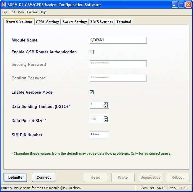
605M-D1 GPRS Modem                                                                                 User Manual

Thank you for your selection of the ELPRO 605M-D1 GPRS Modem. We trust it will give you many years of valuable
service.

                                                      ATTENTION!
                                        Incorrect termination of supply wires may
                                      cause internal damage and will void warranty.
                                       To ensure your 605M-D1 enjoys a long life,
                                        double check ALL your connections with
                                                   the user’s manual
                                              before turning the power on.

All equipment must be properly grounded for safe operations. All equipment should be serviced only by a qualified
technician.

man_605M-D1_1.5.doc                                                                                        Page 2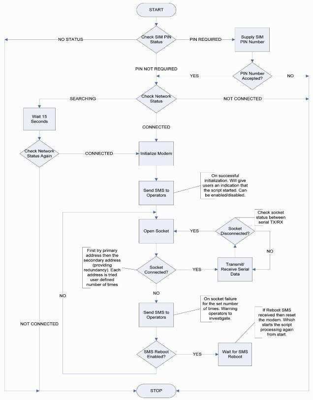
Chapter One                                                                                                     Introduction

Important Notice
ELPRO products are designed to be used in industrial environments, by experienced industrial engineering personnel
with adequate knowledge of safety design considerations.
ELPRO products are designed to operate in the presence of noise and interference, however in an extreme case, noise
and interference could cause product operation delays or operation failure. Like all industrial electronic products, ELPRO
products can fail in a variety of modes due to misuse, age, or malfunction. We recommend that users and designers
design systems using design techniques intended to prevent personal injury or damage during product operation, and
provide failure tolerant systems to prevent personal injury or damage in the event of product failure. Designers must warn
users of the equipment or systems if adequate protection against failure has not been included in the system design.
Designers must include this Important Notice in operating procedures and system manuals.
These products should not be used in non-industrial applications, or life-support systems, without consulting ELPRO
Technologies first.
As a license free, quad band capable product, the 605M-D1 GSM/GPRS modem must used in accordance with local
regulatory and communications authority guidelines. This includes the use of antenna and other radio communications
accessories which form part of the communications between points in the network.
To avoid the risk of electrocution, The antenna, coaxial, and serial cables and all terminals of the 605M-D1 module should
be electrically protected. To provide maximum surge protection, the module should be connected to a suitable earth and
the module should be installed as recommended in the Installation Guide.
To avoid accidents during maintenance or adjustment of remotely controlled equipment, all equipment should be first
disconnected from the 605M-D1 module during these adjustments. Equipment should carry clear markings to indicate
remote or automatic operation. E.g. "This equipment is remotely controlled and may start without warning. Isolate at the
switchboard before attempting adjustments."
The 605M-D1 module is not suitable for use in explosive environments without additional protection.
To minimise any implementation problems, prior to commissioning in the field it is strongly recommended that:
    • A check is performed to ensure reliable signal strength is available at the proposed installation site.
    • The configuration/operation of the modem is tested on a work bench.
Repairs to the 605M-D1 GSM/GPRS modem should only be attempted by ELPRO personnel or upon consultation with
ELPRO, its nominated representative and/or qualified technical personnel.

DO NOT:
    • Operate the equipment near electrical blasting caps or in an explosive atmosphere
    • Operate the transmitter when someone is within 20 cm (~ 8 inches) of the antenna.
    • Operate the transmitter unless all RF connectors are secure and any open connectors are correctly terminated.

Page 3                                                                                                      Dec 2009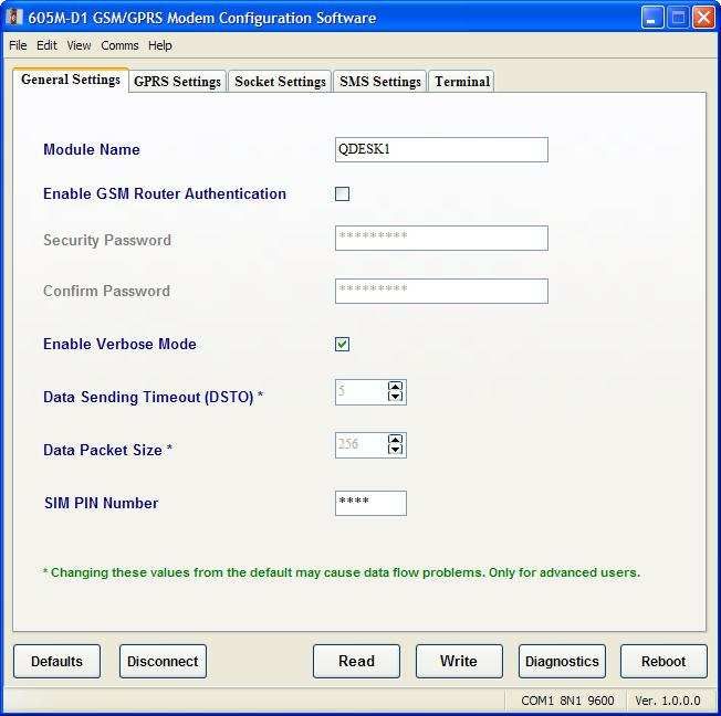
605M-D1 GPRS Modem                                                                                       User Manual

Limited Lifetime Warranty, Disclaimer and Limitation of Remedies
ELPRO products are warranted to be free from manufacturing defects for the “serviceable lifetime” of the product. The
“serviceable lifetime” is limited to the availability of electronic components. If the serviceable life is reached in less than
three years following the original purchase from ELPRO, ELPRO will replace the product with an equivalent product if an
equivalent product is available.
This warranty does not extend to:
    - failures caused by the operation of the equipment outside the particular product's specification, or
    - use of the module not in accordance with this User Manual, or
    - abuse, misuse, neglect or damage by external causes, or
    - repairs, alterations, or modifications undertaken other than by an authorized Service Agent.
ELPRO’s liability under this warranty is limited to the replacement or repair of the product. This warranty is in lieu of and
exclusive of all other warranties. This warranty does not indemnify the purchaser of products for any consequential claim
for damages or loss of operations or profits and ELPRO is not liable for any consequential damages or loss of operations
or profits resulting from the use of these products. ELPRO is not liable for damages, losses, costs, injury or harm incurred as
a consequence of any representations, warranties or conditions made by ELPRO or its representatives or by any other party,
except as expressed solely in this document.

man_605M-D1_1.5.doc                                                                                              Page 4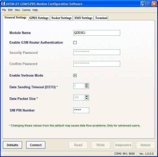
Chapter One                                                                                                                         Introduction

CONTENTS
CHAPTER ONE                        INTRODUCTION ............................................................................ 7

CHAPTER TWO                      INSTALLATION ............................................................................... 8
2.1       GENERAL ........................................................................................................................ 8
2.2       POWER SUPPLY ............................................................................................................... 8
2.3       RS-232 SERIAL PORT...................................................................................................... 9
2.4       ANTENNA PORT ............................................................................................................ 10
2.5       GROUND TERMINAL ...................................................................................................... 10
CHAPTER THREE                           OPERATION............................................................................. 11
3.1       OPERATING MODES...................................................................................................... 11
3.2       AUTOMATIC CONNECT MODE ....................................................................................... 11
3.3       AT COMMAND MODE ................................................................................................... 11
CHAPTER FOUR                         CONFIGURATION..................................................................... 12
4.1    CONFIGURATION USING CONFIGURATION UTILITY SOFTWARE ...................................... 12
  4.1.1 Installing Configuration Utility Software ................................................................ 12
  4.1.2 Startup and Connection............................................................................................ 15
  4.1.3 Configuration ........................................................................................................... 17
  4.1.4 Diagnostics Using Configuration Utility ................................................................. 23
  4.1.4 Configuration Utility Terminal ................................................................................ 25
4.2    CONFIGURATION USING AT COMMANDS....................................................................... 27
  4.2.1 FTP File Transfer..................................................................................................... 27
  4.2.2 SMS Messsaging...................................................................................................... 30
  4.2.3 Network Signal Survey ............................................................................................ 31
  4.2.4 Jamming Detection and Reporting .......................................................................... 31
  4.2.5 Configuring the GPRS Access................................................................................. 31
  4.2.6 EASY GPRS Outgoing Connection ........................................................................ 32
  4.2.7 Request the GPRS context to be Activated ............................................................. 33
  4.2.8 EASY GPRS Incoming Connection ........................................................................ 34
CHAPTER FIVE                      SPECIFICATIONS ......................................................................... 37
5.1       MODULE DIMENSIONS .................................................................................................. 37
5.2       MODULE SPECIFICATIONS ............................................................................................. 38
APPENDIX A AT COMMAND SUMMARY .................................................................. 39

APPENDIX B GLOSSARY ............................................................................................... 49

APPENDIX C MOBILE NETWORK CODES ............................................................... 51

APPENDIX D AUTOMATED CONNECTION FLOW................................................. 55

Page 5                                                                                                                            Dec 2009
605M-D1 GPRS Modem                                                                         User Manual

APPENDIX E CONNECTION SCENARIOS ................................................................. 56

APPENDIX F WORLD GPRS SETTINGS ..................................................................... 58

man_605M-D1_1.5.doc                                                                                Page 6
Chapter One                                                                                      Introduction

Chapter One                                            INTRODUCTION
This user manual outlines the features, mounting, operating parameters, connection, safe use and
configuration of the 605M-D1 modem. When used in conjunction with the ELPRO 605M-R1 Router, the user
manual for the 605M-R1 must be consulted prior to configuration and commissioning. Failure to consult with
the 605M-R1 manual may result in the warranty being voided.
The ELPRO 605M-D1 is a GSM Mobile Stations (MS class B) device capable of using GSM Circuit Switched
Data (CSD), Fax and Short Message Services (SMS) communications and output. The 605M-D1 is a quad
band, GPRS device communicating at GSM-850 / EGSM-900 / DCS-1800 / PCS-1900 MHz, Class 10 GPRS
data packet transfer. It has an embedded TCP/IP stack and DNS query protocol supporting static and dynamic
IP address allocation, PPP, UDP and FTP functionality.
Programming of the 605M-D1 modem in use is either via the ELPRO provided configuration utility, or via AT
Commands (GSM 07.07 and 07.05) listed later in this user manual. Connection to the host controller (Data
Terminal Equipment DTE) is established through one RS232 standard port which also performs serial bi-
directional Data and Fax transfer. Use of the 605M-D1 will require third party products and/or services such as
telecommunications access.
The 605M-D1 AT command set listed later in this manual also features:
Network quality Detection - allowing scanning of all GSM (without SIM) channels to ascertain which provider
has the best signal, most channels and/or transceiver base stations in optimizing service provision.
Jam Detect and Reporting - reporting attempts at interfering with the GSM radio signal (reported as an
unsolicited message on the RS232 port).

Page 7                                                                                          Dec 2009
605M-D1 GPRS Modem                                                                                  User Manual

Chapter Two                                                   INSTALLATION
2.1                                                                                              General
The 605M-D1 module is housed in an rugged aluminium case, suitable for DIN-rail mounting..
All connections to the module must be SELV. Normal 110-250V mains supply should not be connected to any
terminal of the 605M-R1 module. Refer to Section 2.2 Power Supply.
Before installing a new system, it is preferable to bench test the complete system. Configuration problems are
easier to recognize when the system units are adjacent.
The foldout sheet 605M-D1 Installation Guide provides an installation drawing appropriate to most applications.
Further information is detailed below.
Each 605M-D1 module should be effectively earthed via the "GND" terminal on the 605M-D1 module - this is to
ensure that the surge protection circuits inside the 605M-R1 module are effective.

2.2                                                                                  Power Supply
The 605M-R1 module can be powered from a 12 - 24VDC power supply. The positive side of the supply must not be
connected to earth. The supply negative is connected to the unit case internally. The DC supply may be a floating
supply or negatively grounded.
The power requirements of the 605M-R1 unit are 1200mA @ 12V or 900mA @
24VDC.
Power connection is made by the included cable. Connect the Green “GND” and
Black “GND / A” wires to the supply negative, and connect the Red “POWER+”
to the supply positive.
The white “SENSE / B” wire is available for sensing modem connection status,
but is not required for power supply connection.

                                                                                       GND/A       GND

                                                                                      SENSE/B      PWR+

                                                                               Power connector Pin assignment

                 Supplied Power Cable

man_605M-D1_1.5.doc                                                                                         Page 8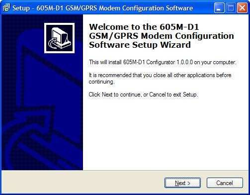
Chapter Two                                                                                      Installation

2.3                                                                       RS-232 Serial Port

The serial port is a 9 pin DB9 female and provides for
connection to a host device as well as a laptop computer
for configuration, field testing and for factory testing.
Communication is via standard RS232 signals. The 605M-
D1 is configured as DCE equipment with the pinouts
detailed below.

DB9 Connector Pinouts

Pin    Name     Direction      Function
1      DCD      Out            Data carrier detect –

2      RD       Out            Transmit Data – Serial Data Output
3      TD       In             Receive Data – Serial Data Input
4      DTR      In             Data Terminal Ready -
5      SG                      Signal Ground

6      DSR      Out            Data Set Ready - always high when unit is powered on.
7      RTS      In             Request to Send -
8      CTS      Out            Clear to send -
9      RI       Out            Ring indicator -

                              2           2                       2       2
                        RD                    RD            RD                RD
                              3           3                       3       3
                         TD                    TD            TD                TD
                              5           5                 SG    5       5   SG
                        SG                    SG
                              7           7                       7       7
                        RTS                   RTS           RTS               RTS
                              8           8                       8       8
                        CTS                   CTS           CTS               CTS
                              6           6                       6       6
                        DSR                   DSR           DSR               DSR
                              4           4                       4       4
                        DTR                   DTR           DTR               DTR
                              1           1                       1       1
                        DCD                   DCD           DCD               DCD
                      MODEM               DCE HOST      MODEM             DCE HOST
                        DB9                  DB9          DB9               DB9
                       MALE                FEMALE        MALE              MALE

Hardware handshaking using the CTS/RTS lines or using XON/XOFF protocol is provided.
Example cable drawings for connection to a DTE host (a PC) or another DCE hosts (or modem) are detailed above.
When operating In Automatic Connect mode, the DCD signal goes high when the modem has established a
connection to the remote device.

Page 9                                                                                              Dec 2009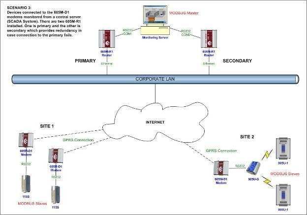
605M-D1 GPRS Modem                                                                                   User Manual

2.4                                                                                    Antenna Port
The ELPRO 605M-D1includes a SMA bulkhead female, class 4 (2W)
co-axial connector for the external antenna.
NOTE: BEFORE connecting the ELPRO 605M-D1 to a Power Supply
source, a suitable Antenna shall be connected and properly installed.
The antenna has to be installed with care in order to avoid any
interference with other electronic devices and has to guarantee a
minimum distance from persons (20 cm). In case this requirement
cannot be satisfied, the system integrator has to assess the final
product against applicable SAR regulations.
For good efficiency of the antenna and minimum interference with other electronic systems, a space of min. 40 cm
around the radiating part should be free, at least of electrically conducting materials (except the ground plane on
which it is attached).
Less distance and less obstacles there are between the antenna connected to the ELPRO 605M-D1and the antenna
of the GSM/GPRS network base station, the less power is radiated by the Terminal under normal conditions and the
higher is the safety margin in case of disturbances.
A check of eventual interferences can be made when the ELPRO 605M-D1transmits at maximum power level to
register to a GSM 900 network (see frequency channel numbers), immediately after being switched on.

Antenna Type
For best performance, ensure the antenna is of the correct type.
Frequency range Standard Dual Band GSM/DCS frequency range or Standard Quad Band GSM/DCS/PCS
frequency range if used for all four bands
ELPRO provides the CFD890-EL antenna for this application.

2.5                                                                            Ground Terminal
A Ground Terminal is provided on the back of the
module. This Terminal should be connected to the
Main Ground point of the installation in order to
provide efficient surge protection for the module
(refer to the Installation Diagram).

man_605M-D1_1.5.doc                                                                                        Page 10
Chapter 4                                                                                          Configuration

Chapter Three                                                         OPERATION
3.1                                                                        Operating Modes
The 605M-D1 operates in one of two modes, Automatic Connect Mode or AT Command Mode.
Automatic Connect Mode allows the modem to operate with host equipment that is not designed to operate with
modems. The modem makes a connection to a pre-configured TCP port and location, then transparently transfers
data over the configured connection.
AT Command Mode is used when the host equipment is designed to operate with a modem. The host equipment
needs to support AT commands to command the modem to make the required connections.

3.2                                                               Automatic Connect Mode
In this mode, the modem automatically make a connection between the onboard RS-232 serial port and a TCP
connection point (port) on a remote device which is connected to the internet. This socket may be either an internal
connection point (TCP port) on a 605M-R1 Device Server, to a virtual serial port on a PC, or any other TCP socket
with access to the internet.
Automatic Connect mode is configured with the supplied 605M-D1 Configuration utility. Refer to the Configuration
Manual (man_605M-D1-Config) for detail on how to use the configuration utility to test, diagnose, and configure the
modem.
At power-up, the modem waits 10 seconds to allow access by the configuration utility. If the modem receives any
configuration commands during this time, it will abort the start up sequence and wait for further commands.
Note: Because of this behavior, it is important to ensure that any host equipment does not send any data containing
the sequence “AT” within 10 seconds of power-on. The RS-232 DCD pin will be low until the modem makes a
connection to the remote TCP device. The “SENSE” wire on the power connector will go active low when the modem
makes a connection to the remote TCP device.
After 10 seconds, the modem attempts to connect to the cellular network. On connection, the modem optionally
sends an SMS message to report that it has connected. Once it is connected to the cellular network, it attempts to
connect to a TCP port on a remote device. If the connection is lost, or if the connection cannot be made, the modem
may be configured to attempt to connect to a redundant secondary socket location. If both the primary and
redundant secondary socket are unavailable, the modem can be configured to send an alarm message via SMS. At
this stage, the modem may be configured to either wait for an SMS message commanding it to restart, or can be
configured to re-try the connection to the primary and secondary connection locations.

3.3                                                               AT Command Mode
In this mode, the modem waits for AT Commands from the host device. The host device must be able to issue the
appropriate AT commands to force the modem to perform the required behavior. This mode provides full access to
all of the features of the modem, including SMS, TCP-IP connection, and FAX data.
At power up, the modem issues the prompt “OK”, and then waits for commands from the host. At this point the host
can issue AT commands to:
    • Send an SMS Message
    • Make a TCP-IP connection to a remote device
    • Make a serial data connection to a remote device
    • Transfer data to a remote FTP server
    • Refer to Appendix A for a full list of supported AT commands.

Page 11                                                                                                   Dec 2009
605M-D1 GPRS Modem User Manual
Chapter Four CONFIGURATION
Configuration of the 605M-D1 modem is performed using the AT Command set. ELPRO provides a configuration
utility to simplify the configuration of modems operating in Automatic Connect mode.. A simple and intuitive interface
allows easy selection of the required functionality, then the configuration utility sends the AT commands to the
modem to set up the requested configuration.
4.1 Configuration using Configuration Utility Software
The configuration utility allows you to
configure the modem for operation in
Automatic Connect mode. The
configuration utility is available on the CD
supplied with your modem, or the latest
version may be downloaded from ELPRO’s
web-Site (www.elprotech.com). To install,
download the file “inst_605M-D1_v1-0.exe”
and run this file.
The following sections describe how to use
the configuration utility.
The configuration software allows for the
easy setup and configuration of ELPRO’s
605M-D1. It is Microsoft Windows based
software that lets a user easily configure the
modem without the need to remember
complex AT command sequences.
The configuration software also enables a
user to save/read configuration data to a file
which can be used for quick backup or mass
deployment of the 605M-D1 modem settings.
Another handy feature of the configuration
software is that it comes with a built-in
terminal emulator which eliminates the need
to use external terminal software. It is
especially useful for people who want to use advanced AT command set for configuring the modem and provides a
unified compact solution.
The configuration software allows for redundant connection setup where the 605M-D1 modems can connect to a
secondary address in case the primary becomes unavailable. This feature is especially useful in high availability
scenarios.
In addition to the easy to use GUI for configuring the 605M-D1 modems, the configuration software also enables the
user to get advanced diagnostics information like signal strength, available providers, IMEI number, SIM PIN status
etc.
4.1.1 Installing Configuration Utility Software
System Requirements,
OS: Windows 98/2000/XP/Vista (Although it’s been tested to work with older windows operating systems. It is
designed to work best with XP and over.)
• CPU 1 GHz or over (P4 2 GHz or more recommended)
• 128 Mb RAM (at least 256 Mb recommended)
• 10 Mb free disk space
• 800 x 600 screen resolution (recommended 1024 x 768 or more)
• 1 RS-232 serial port
man_605M-D1_1.5.doc Page 12Chapter 4 Configuration
Double click on the “inst_605M-D1.exe” file to start the
installation
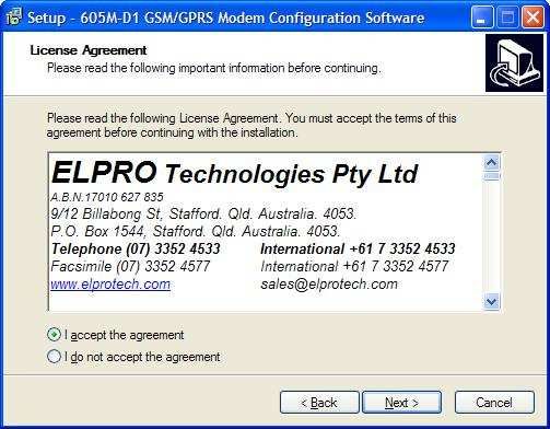
Click Next to see the License Agreement. Read it and
accept it if you wish to proceed.
Select a different location or click Next to proceed
Click Next to proceed
Page 13 Dec 2009605M-D1 GPRS Modem User Manual
Check “Create a desktop icon” if you wish to have a
desktop shortcut installed. Click Next to proceed
Click Install
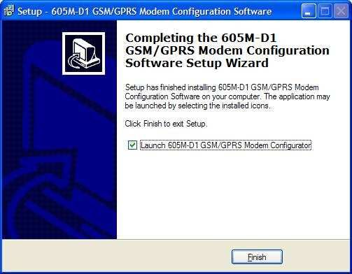
Click Finish to complete the installation. The
configuration software is now successfully installed
and ready to be used.
man_605M-D1_1.5.doc Page 14Chapter 4 Configuration
4.1.2 Startup and Connection
Launch the 605M-D1 GSM/GPRS Configuration Software by clicking on Start > Programs > 605M-D1 Config >
605M-D1 Configurator. If the configuration software is used for the first time it will display factory default values for all
the settings. On subsequent uses it will automatically load the most recent configuration data that was entered.
Command Menu Tabular Settings Page and Terminal Window
Easy Access Software Version
Context Sensitive Help Serial Port
Command Buttons Number
Messages Settings
Page 15 Dec 2009605M-D1 GPRS Modem User Manual
Serial Port Settings:
All 605M-D1 modems have a fixed factory default serial baud rate of 9600. Any
changes to this speed should be reflected in the serial port settings while
establishing the connection to the modem.
If a com port is not already selected then the serial port settings window is
automatically displayed when you hit the Connect button. Alternatively, it can be
displayed by clicking on the command menu, Comms > Serial Port Setup
The default comm. port settings for connecting to a 605M-D1 modem are,
Baud Rate : 9600
Data Bits : 8
Parity : None
Stop Bits : 1
Flow Control : None
As you may notice that these fields are disabled by default and don’t need to be
changed. However, if you do need to change these settings then you have to
select “Advanced Config” which is discussed later under the section Configuration
> Advanced Config.
NOTE: Setting the serial baud rate of the 605M-D1 modem to auto (AT+IPR=0) may cause problems while
performing diagnostics. Therefore, it is recommended to keep the serial baud rate to a fixed value.
Serial Connection:
Connect the 605M-D1 modem’s RS-232 port to the serial port of the host PC and power it up. Once the modem is
powered up it can go into two modes,
Automated Connection Mode: This is an ELPRO proprietary design and lets the 605M-D1 modems establish a
M2M connection in conjunction with the 605M-R1 GSM/GPRS Routers. The 605M-D1 modem is programmed to go
into the automated connection mode based on the stored configuration data if it does not receive an AT command
on its RS232 port within 10 seconds of power up (booting). Refer to Appendix D for the automated connection mode
flow diagram.
AT Command Mode: This is the mode we need to
be in for talking to the modem through the
configuration software. The easiest method is to
initiate connection from the configuration software
within 10 seconds of power up. The configuration
software automatically sends an AT and you should
get an OK back on successful connection. Failure to
get an OK reply means you don’t have the AT
command mode or there is some other problem in
communication with the modem (check serial
connection and/or power cycle the modem).
man_605M-D1_1.5.doc Page 16Chapter 4 Configuration Alternatively, you can remove the SIM card from the 605M-D1 modem on startup which aborts the automated connection and returns to the AT command mode. NOTE: Once the modem goes into the automated connection mode it takes control of the RS232 port and you are not able to communicate to it using AT commands. The modem will need to be power cycled to get back the AT command mode. 4.1.3 Configuration The configuration software lets users configure the automated connection mode for the ELPRO 605M-D1 modems through an easy to use graphical user interface. It eliminates the need for the user to remember complex AT commands. The configuration software can also be used to conveniently Save/Load configuration data To/From a file on a storage medium. This is very handy to quickly deploy a configuration profile to multiple modems or for backup purposes. We don’t actually need to be connected to the 605M-D1 modem while modifying the various configuration settings. The modem needs to be connected only while performing a modem Read/Write operation or while running diagnostics. Various configuration settings are required by the 605M-D1 modems to successfully enable the M2M automated connection mode. The different configuration settings and other features are discussed in detail in the following sections. Advanced Config: Some settings in the configuration software are disabled by default. These settings are generally not meant to be changed and are only for advanced users. Any such advanced settings are highlighted throughout this document. In case you need to enable these advanced settings, from the command menu click on View > Advanced Config or use the shortcut key Ctrl+F12. WARNING: Advanced settings are only meant for advanced users. Changing these from defaults may cause connection and data flow problems. Page 17 Dec 2009
605M-D1 GPRS Modem                                                                                  User Manual

General Settings:
Module Name: It is used to define a name for
the 605M-D1 modem (max. 20 chars). This
name is prepended to any outgoing SMS
messages from the modem. Please try to use a
name that is unique and easily identifiable by
the operators.
Enable GSM router Authentication: This
setting needs to be enabled only if you use
password authentication while connecting
through an ELPRO 605M-R1 router. It provides
an extra level of security on the 605M-R1 router
side to drop any unsolicited TCP connections.
The password fields (max 32 chars) are enabled
once this setting is enabled and the proper
password needs to be entered.
Enable Verbose Mode: Check this if you need
to see verbose messages in the terminal
window while the 605M-D1 modem is running in
the automated connection mode. This setting is
great for debugging any connection problems.
An operator has to just look at the terminal
window and identify the problem point.
However, it is advised to disable verbose mode
once the connection has been tested. This
prevents unnecessary recording of these debug
messages by the attached devices upon
deployment.
Data Sending Timeout (DSTO): This sets the
maximum time that the modem waits before sending
anyway a packet whose size is less than the one
defined by the Data Packet Size field. It is defined in
100ms units (10 = 1 sec). A value of 0 means that it
waits forever for the defined packet size to arrive. The
timeout starts when the beginning of the data packet
arrives at the modem
The default timeout value is 5 (500ms). This is an
advanced setting and does not need to be changed
for normal operations. The time out begins from the
time the first character in the data packet arrives at
the modem.
Data Packet Size: This is an advanced setting that
sets the packet size in bytes to be used by the TCP/IP
stack for sending data. The default value is 256 (max
value = 1500).
SIM PIN Number: This field is used to define the SIM
card PIN number (max 8 chars) in case SIM PIN
security is enabled on the 605M-D1 modem. It
provides a great level of security against SIM card
theft. If SIM PIN security is enabled then the modem
will try to automatically enter this PIN on startup. If the
PIN number is incorrect then it will immediately abort
any further process of the automated connection mode. Exercise care while using this setting. Please refer to the
section Diagnostics > PIN Code Request for more information.

man_605M-D1_1.5.doc                                                                                        Page 18
Chapter 4                                                                                           Configuration

GPRS Settings:
This defines the various settings for
successfully opening a GPRS connection.
GPRS settings differ between mobile service
providers around the world (refer to Appendix 3
for a non exhaustive list). Please consult your
service provider for the proper GPRS settings.
Access Point Name: This is the default GPRS
internet access point name of your mobile
service provider.
GPRS User ID: This is the User ID to be used
for the GPRS connection.
GPRS Password: This is the password to be
used for the GPRS connection.
IP Address: This can be used to define an IP
address for your GPRS connection. The default
value is 0.0.0.0 which indicates that the 605M-
D1 modem will get a dynamic IP from the
service provider. This is an advanced setting
and does not need to be changed. You will only
change this if you have a static public IP
assignment from your service provider.
Socket Settings:
These are the settings needed to successfully
establish a TCP socket connection with the end
device. The 605M-D1 is designed to work best
with a 605M-R1 GSM/GPRS Router. All the
605M-D1 modems connect to the TCP port of
605M-R1 router over the GPRS network, which is
then responsible for intelligently routing data
between the modems (Please refer to Appendix 2
for connection scenarios).
Primary Host Address: Enter the IP address or
domain name of the primary device the 605M-D1
modem will connect to.
Primary TCP Port Number: Enter the TCP port
number of the primary device the 605M-D1
modem will connect to.
Enable Secondary Address: Check this box if
you have a secondary device for the 605M-D1
modems to connect to incase the primary is
unavailable. This provides redundancy in high
availability scenario for continued operation.
Secondary Host Address: Similar to primary this
defines the secondary host IP address or domain
name when the secondary address is enabled.
Secondary TCP Port Number: Similar to primary this defines the secondary TCP port number when the secondary
address is enabled.
Primary/Secondary Address Retry: This defines the number of times the primary and secondary addresses will be
tried before the modem decides that something is wrong and sends out a warning SMS to operators. Default value is
3. You can increase this to a higher value. However, please note that no warning SMS will be sent out till it has tried
that number of times. A better option is to use a moderate value in conjunction with “Remote SMS Reboot”, and/or
“Total Number of SMS sent” discussed later.

Page 19                                                                                                    Dec 2009
605M-D1 GPRS Modem                                                                                    User Manual

Socket Retry Time: This is the time in seconds to wait between address retries to open a TCP socket connection.
The default value is 15 seconds. This gives the modem sufficient time to recover in case of signal drops or other
temporary connection problems.
Socket Inactivity Timeout: This is the time in seconds to retry socket connection in case of data inactivity over the
socket connection. The default value is 600 seconds = 10 minutes. You may want to modify it to a higher or lower
value according to the polling period of the attached device (maximum 18 hours). For example, if an attached slave
device is polled every 15 minutes by a master device then you need to set the socket inactivity timeout to a value
greater than that (say 910 seconds). To disable, set to Zero.
Note: Each time the inactivity timeout occurs, the modem will disconnect and re-connect the socket in an attempt to
recover the connection. This may incur a service charge from your operator, so it is important to ensure that you do
not leave the modem powered with no activity when the inactivity timeout is enabled.

SMS Settings:
This is where all messaging related setting like
phone numbers, short messages etc are
defined.
SMS on successful Initialization: Enable this
setting if an SMS is needed on the successful
initialization of the 605M-D1 modem when it
gets into the automated connection mode. The
text box can be used to modify the default
outgoing message. The module name is
automatically appended to the message for
easy identification by the operator. For
example, this setting is very useful when
“Remote SMS Reboot” is enabled to get an
indicative SMS that the modem has actually
rebooted and commenced automated
connection.
SMS on socket Failure: This setting is used to
enable/disable SMS warning after the set
number of socket connection retries have
failed. It is enabled by default (recommended).
If it is disabled then no SMS will be sent out to
the operators on connection failures. The text
box can be used to modify the default outgoing
message. The module name is automatically
appended to the message for easy
identification by the operator.
SMS Retry: The number of times the 605M-D1 modem will retry to send the messages in case of failures.
Total Number of SMS Sent: If Remote SMS Reboot is not enabled then the 605M-D1 modem is designed to
repeatedly retry connection after the failure SMS has been sent. This setting is used to set the maximum number of
SMS that will be sent out per phone number after which any further SMS sending is stopped. This avoids sending out
endless SMS messages to the operators on every repeated failed connection attempt and provides a SMS capping
mechanism for significant cost savings.
Phone Number 1: Enter the phone number of the operator that gets the enabled SMS messages. Please follow the
same numbering format as you would use to send SMS through any other GSM device (mobile) in that area.
Phone Number 2: Same as phone number 1 this setting can be enabled to send SMS to a second operator.
Phone Number 3: Same as phone number 1 this setting can be enabled to send SMS to a third operator.
Remote SMS Reboot: This setting can be used to enable/disable the remote rebooting of the 605M-D1 via an SMS
message. The text box can be used to modify the trigger string (case insensitive). When this setting is enabled, the
modem will wait for an SMS message containing the reboot trigger string indefinitely once the number of socket
connection retry has failed. If the SMS on Socket Failure is enabled then an indicative string “SMS reboot enabled” is
also appended to the outgoing SMS message. This is useful to remind operators on connection failures that the
605M-D1 modem can be rebooted by sending an SMS to it. As an example, this setting is especially useful in

man_605M-D1_1.5.doc                                                                                         Page 20
Chapter 4                                                                                         Configuration

planned downtime scenarios where the operators don’t want the modem to continuously retry connection but rather
wait for the reboot SMS to resume connection.

Default Settings:
Sometimes it may be required by the user to
quickly return all the settings in the
configuration software to their factory default
values. This can be easily done by clicking
on the “Defaults” easy access command
button.
WARNING: Using this button will clear all the
fields to default values. Please make sure
you save any custom configuration to avoid
entering it all again.

Write Configuration Data to Modem:
Any settings entered in the configuration software are not actually written to the 605M-D1 modem until you click on
the “Write” command button. Please make sure that the modem is connected and you have AT command mode
before doing this.
A progress bar is displayed indicating the amount of configuration data written to the modem. Once the transfer is
complete you should get a message indicating the successful completion of the process.

Page 21                                                                                                  Dec 2009
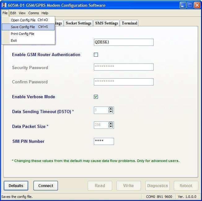
605M-D1 GPRS Modem                               User Manual

Read Configuration Data from Modem:
The configuration software settings
can be easily populated by reading
values from a pre configured modem.
This is very handy to replicate or
verify configuration data written on the
605M-D1 modem.
To read data from the modem click on
the “Read” command button.
The cursor changes into an hourglass
during the read operation. In case
there is no configuration data present
on the modem (fresh out of box) the
configuration software will indicate
that with an error message.
NOTE: The easiest way to verify read
operation is to set the configuration
software to default values and then
read from the modem. This should
repopulate all the fields with the
values as read from the modem.

Save Configuration Data to File:
Data from the configuration software can be
easily saved to a file on a storage medium.
This feature is very useful for making
backups of the configuration data.
To save configuration data to a file click on,
File > Save Config File from the command
menu. Alternatively you can also press the
shortcut key Ctrl+S.
Now browse to the desired path and choose
a suitable filename from the Save As popup
dialog box.

man_605M-D1_1.5.doc                                  Page 22
Chapter 4                                               Configuration

Load Configuration Data from File:
Saved configuration data files can be easily
loaded back into the configuration software for
quick restoration. This feature also greatly
reduces the time for mass deployment of 605M-
D1 modems with similar configuration settings.
To load configuration data from a file click on, File
> Open Config File from the command menu.
Alternatively you can also press the shortcut key
Ctrl+O.
Now browse to the path and choose the desired
configuration data file from the Open popup dialog
box.

4.1.4 Diagnostics Using Configuration Utility
The configuration software can be used to
easily get basic diagnostics information out of
the 605M-D1 modem. The diagnostics screen
can also be used to enable/disable SIM PIN
security.
Connect to the 605M-D1 modem and click on
the “Diagnostics” command button to get the
diagnostics screen.
The configuration software will prompt you to
make sure that the SIM card is inserted. The
SIM card needs to be inserted into the 605M-
D1 modem to successfully retrieve all the
diagnostics information.

Page 23                                                      Dec 2009
605M-D1 GPRS Modem                                                                                   User Manual

You will to get to the following diagnostics screen,
Click on the “Get Data” button to retrieve the diagnostics
information and populate the fields. More detailed
information about the each option is presented in the
following sections.
Signal Strength:
The green bar indicates the received signal strength by
the 605M-D1 modem. One bar indicates low signal
strength and all four bars indicate a very good signal
reception. For the advanced users the exact signal
strength value in dBm is also indicated.
There is also provision to automatically refresh the
signal strength at set repeated intervals in seconds. This
is especially useful to perform a site signal survey to find
the best installation location for the 605M-D1 modems.
IMEI Number:
This retrieves the International Mobile Equipment
Identity serial number. The IMEI number is used by
the GSM network to identify valid devices and
therefore can be used to stop a stolen device from
accessing the network. It is also a useful identifier for
maintaining an asset register.
SMS SCN:
This indicates the Service Center Number for sending
out SMS. Mobile service providers usually have
multiple service center numbers in case one has a
problem. In most cases this number does not need to
be changed.
However, if there ever is a need to change it to an
alternate number then you can click on the “Change
SCN” button to easily modify it.
WARNING: Entering the wrong SMS Service Center
Number will disable any outgoing message. Please
use caution while changing this number.
PIN Code Request:
This indicates if SIM PIN security is enabled or not. It can also
be used to actually turn on/off the SIM PIN code request on
startup. SIM PIN security is very useful if you want to protect
the SIM card from unauthorized use.
Once the PIN code request is turned ON the PIN number can
also be modified by clicking on the “Change PIN” button.
If the PIN code request is turned ON then we also need to
specify this SIM PIN number under the general settings of the
configuration software. Otherwise the 605M-D1 modem will fail
to enter the automated connection mode.

In most cases the default SIM PIN number is 0000. However,
please double check with your mobile service provider.

WARNING: Please exercise caution while using SIM PIN
security and changing the PIN number. Don’t forget to specify
the correct SIM PIN number under the general settings. Always remember the PIN number and if possible write it
down and store it in a safe place. Repeated failed attempts to enter the correct PIN number will lock the SIM card

man_605M-D1_1.5.doc                                                                                        Page 24
Chapter 4 Configuration
permanently. You will have to contact your mobile service provider to get it unlocked and in some cases it may even
by rendered useless and need to be replaced.
Available Providers:
The 605M-D1 modem scans and displays the name of all the mobile network operators servicing the area. It may
take a few seconds to display this information as the modem does a network scan. Operator names are displayed in
separate lines in the following format.
+COPS: (, ,””, )
Where Operator Availability,
0 = unknown
1 = available
2 = current
3 = forbidden
For Example,
+COPS: (2,”AUS OPTUS”,””,”50502”)
+COPS: (3,"AUS VODAFONE","","50503")
For more detailed information please refer to AT+COPS in the AT commands guide.
When the 605M-D1 modem starts up it automatically selects the service provider based on the SIM card. In case of
connection problems this information can be used to verify the mobile operator network the modem is actually
connected to. This information is also useful if a person needs to find any other alternate mobile network operators
servicing the area.
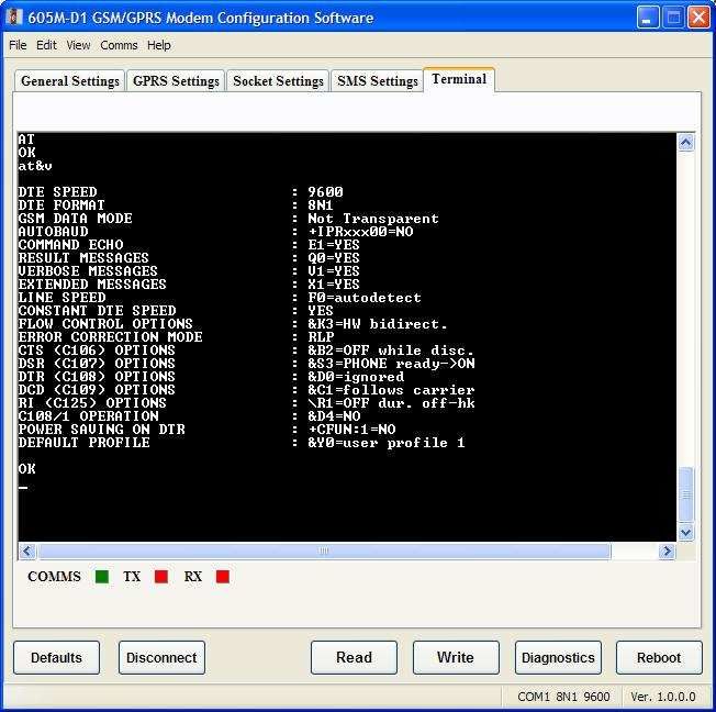
4.1.5 Configuration Utility Terminal
The configuration software comes built-in with a terminal emulator that can be used to interact with the 605M-D1
modems using AT commands. There is no need to have separate terminal software (like hyper terminal, procomm
etc) for basic usage and provides an easy unified solution.
Page 25 Dec 2009605M-D1 GPRS Modem User Manual
The Terminal window also has 3 status lights for easy visual inspection of the status of the serial connection.
COMMS: Green when connected to a modem. Red when disconnected.
TX: Green when data is being transmitted. Red when idle.
RX: Green when data is being received. Red when idle.
NOTE: The built-in terminal emulator is designed to work exclusively with ELPRO’s 605M-D1 GSM/GPRS modems.
Usage with any other product is not supported and may cause undesirable effects.
man_605M-D1_1.5.doc Page 26Chapter 4 Configuration
4.2 Configuration using AT Commands
Depending on the application, it may be necessary to access the full functionality of the 605M-D1 using the AT
Command set. A list of supported AT commands is provided in Appendix A of this manual. The following sections
describe how to:
• configure the modem for GPRS access
• connect via FTP
• send and receive SMS messages
• and how to check and monitor network status.
NOTE When using Host equipment that controls the modem using AT commands you may want to disable the
Automatic connection mode of operation. To do this, you need to enter the command
AT#ESCRIPT=””
This command only needs to be entered once to disable the automatic connection mode. If automatic connection
mode is not disabled, the host equipment must send AT commands to the modem within 10 seconds after power up
to ensure the modem doesn’t attempt to connect automatically.
4.2.1 FTP File Transfer
A set of AT commands is available to support the FTP activities.
Setting up the FTP Timeout
The first command is called #FTPTO (FTP Time-Out) which defines the time-out for FTP operations. The module has
already a factory default time defined that is 10s.
If it is needed to be modified, the syntax is:
AT#FTPTO[=]
Parameter:
- time-out in 100 ms units
100..5000 - hundreds of ms (factory default is 100)
NOTE: The parameter is not saved in NVM.
NOTE: if parameter is omitted the behavior of Set command is the same as Read command.
Example:
AT#FTPTO=1000 (set the timeout to 100sec)
OK
Opening and Closing an FTP Connection
With the command AT#FTPOPEN=,,, is possible to open the FTP
connection. The parameters are:
- string type, address and port of FTP server (factory default port 21).
- string type, authentication user identification string for FTP.
- string type, authentication password for FTP.
0 - active mode (default)
1 - passive mode
In order to close the FTP connection the AT command AT#FTPCLOSE should be used.
Page 27 Dec 2009605M-D1 GPRS Modem User Manual Setting the FTP Transfer Type With the command AT#FTPTYPE[=] is possible to configure the file transfer type. The command must be provided during an FTP connection. Parameter: - file transfer type: 0 - binary 1 - ASCII NOTE: The command causes an ERROR result code to be returned if no FTP connection has been opened yet. NOTE: If the parameter is omitted then the behaviour of Set command is the same of Read command. FTP File Transfer to the server With the command AT#FTPPUT= , to issued during an FTP connection, is possible to open a data connection and starts sending file to the FTP server. If the data connection succeeds, a CONNECT indication is sent, otherwise a NO CARRIER indication is sent. Parameter: - string type, name under which you choose to save the file on the server (must have the right extension: es. if the file you’re sending is .txt then the can be test.txt) NOTE: use the escape sequence +++ to close the data connection. NOTE: The command causes an ERROR result code to be returned if no FTP connection has been opened yet. Example of an FTP file transfer to the server: Define PDP contest: AT+CGDCONT=1,”IP”, "internet.wind.biz" OK GPRS Context Activation, as response gives IP of the module: AT#SGACT=1,1 #SGACT: 193.199.234.255 OK Opening of FTP connection: AT#FTPTO=1000 (FTP settings of time-out) OK AT#FTPOPEN=”199.188.25.77”,”user”,”pass”,0 OK In this case port of FTP server is not specified, which means that it has the default value: 21 AT#FTPTYPE=0 (FTP settings of file type) OK FTP file transfer to the server in the file named “file.txt”: AT#FTPPUT="file.txt" CONNECT (send the file) +++ (escape sequence +++ to close the data connection) man_605M-D1_1.5.doc Page 28
Chapter 4                                                                                          Configuration

NOCARRIER
AT#FTPCLOSE (closing FTP connection)
OK
Deactivation of GPRS context if required:
AT#SGACT=1,0
OK

FTP File download from the server
With the command AT#FTPGET= , to issued during an FTP connection, opens a data connection and
starts getting a file  from the FTP server.
If the data connection succeeds, a CONNECT indication is sent, otherwise a NO CARRIER indication is sent. The
file is received on the serial port.
Parameter:
 - file name, string type.
NOTE: The command causes an ERROR result code to be returned if no FTP connection has been opened yet.
Example of an FTP file download from the server:
Define PDP contest:
AT+CGDCONT=1,”IP”, "internet.wind.biz"
OK
GPRS Context Activation, as response gives IP of the module:
AT#SGACT=1,1
#SGACT: 193.199.234.255
OK
Opening of FTP connection:
AT#FTPTO=1000 (FTP settings of time-out)
OK
AT#FTPOPEN=”199.188.25.77”,”user”,”pass”,0
OK
In this case port of FTP server is not specified, which means that it has the default value: 21
AT#FTPTYPE=0 (FTP settings of file type)
OK
AT#FTPCWD="incoming" (change working directory if requiered)
OK
In order to get the list of files on the working directory from the server AT command AT#FTPLIST
should be used.
Downloading FTP file “file.txt” from the server:
AT#FTPGET="file.txt"
CONNECT
(receive the file)
Data connection will be closed automatically when the file sending is terminated:
NO CARRIER
AT#FTPCLOSE (closing FTP connection)

Page 29                                                                                                 Dec 2009
605M-D1 GPRS Modem                                                                                   User Manual

OK
Deactivation of GPRS context if required:
AT#SGACT=0
OK

4.2.2 SMS Messsaging
The Modem supports transmission and reception of SMS messaging. To use SMS messaging, you need to configure
a service center address (Phone number). This is done with the AT+CSCA command. To send SMS messages, use
the AT+CMGS command. To receive SMS messages, use the AT+CMGR command. To control the way the modem
reports the arrival of new SMS messages, us the AT+CNMI command.
Note: SMS Messaging is a highly configurable system in the 605M-D1. The following examples assume that all
settings are at their defaults, except for message format which is set to text mode. For more detail on how to use
SMS messaging, refer to ELPRO support for a detailed AT command summary.

Setting the message format
The following descriptions assume text mode for SMS messages. To set text mode, issue the following:
AT+CGMF=1

Setting the service center address
Set the service center address with the AT+CSCA command.
AT+CSCA=,129
Where  is the phone number for the service center. To specify the number in international format (leading
“+” for international numbers,
AT+CSCA=,145

Sending an SMS message.
Send an SMS message with the AT+CMGS command.
AT+CMGS=,129
Where  is the phone number to send the message to. To specify the number in international format
(leading “+” for international numbers,
AT+CMGS=,145.
at this stage, the modem will respond with a string requesting the text message to send. This is ,
, greater-than-symbol “>”, and a space “ “.
Enter the message to send, followed by Ctrl-Z (0x1A) to send the message.

Receiving an SMS message.
Receive SMS messages with the AT+CMGR command.
AT+CMGR=
 is set to 0 for the most recently received message.
If  refers to a valid message, output will be the string
+CMGR: ,,,[optional other parameters]
The  is one of “REC UNREAD” or “REC READ”
 is the sender’s phone number.
 is the time the message was received at the modem.
Refer to the detailed command reference for [optional other paramters].
 is the message data.

man_605M-D1_1.5.doc                                                                                         Page 30
Chapter 4                                                                                             Configuration

If there is no message available at this index, the output is the string
ERROR.

4.2.3 Network Signal Survey
As an aid to network planning, the 605M-D1 provides a feature to scan all available network channels, and report the
signal quality and network name of any detected signals.
To perform a network survey, Issue the command:
AT#CSURV
The modem will respond with the message:
Network Survey Started …
A short time later, the modem will list all detected stations, along with information about each station.
The important values reported are:
rxLev: - This is the received signal level in dBm. A smaller number (less negative) indicates a better signal.
mcc, mnc – These are the Mobile country code and mobile network code. These can be used to identify the network
that the detected base station is a part of.
Some useful country codes and network codes are listed in Appendix C.

4.2.4 Jamming Detection and Reporting
The Jamming Detect & Report feature allows a ELPRO 605M-D1to detect the presence of a disturbing device such
as a Communication Jammer and give indication to the user and/or send a report of that to the network.
This feature is accessed via the #JDR command.
This feature can be very important in alarm, security and safety applications that rely on the module for the
communications. In these applications, the presence of a Jammer device can compromise the whole system
reliability and functionality and therefore shall be recognized and reported either to the local system for
countermeasure actions or to the network providing remote actions.
When Jamming Detection is enabled, the modem will issue a message from it’s RS-232 serial port whenever a
jamming signal is detected. This message will be “#JDR JAMMED”. If the jamming signal is no longer detected, the
modem issues the message “#JDR OPERATIVE”. The modem may also be configured to report the status a
jamming signal on a regular (3 –second) time period.
To disable Jamming detection, issue the command “AT#JDR=0”
To enable Jamming detection with status reporting on change of status, “AT#JDR=2”
To enable Jamming detection with 3-second status reporting, “AT#JDR=4”

4.2.5 Configuring the GPRS Access
The GPRS access configuration is done by setting:
• the GPRS context number 1 parameters (see +CGDCONT command)
• the Authentication parameters: User Name and Password (see commands #USERID, #PASSW)

Configuring the Embedded TCP/IP Stack
The TCP/IP stack behaviour must be configured by setting:
• the packet default packet size (see command #PKTSZ)
• the data sending timeout (see command #DSTO)
• the socket inactivity timeout (see command #SKTTO)

Page 31                                                                                                     Dec 2009
605M-D1 GPRS Modem                                                                                   User Manual

Defining the Internet Peer to be Contacted
As last setting definition, the host to be contacted and on which port/protocol must be set:
• the socket definition (see command #SKTSET)
This command permits also to specify the host name instead of its IP address, if a host name is given to the set
command, then the module stores it as a host nick name. It is care of the module user to guarantee that the host
nick name provided corresponds to an existing internet peer.
If a host nick name has been given then, while opening the connection in response to the AT#SKTOP command, the
module will autonomously activate a GPRS connection and query its DNS to obtain the IP address relative to the
host nick name provided. This process of context activation and DNS query may require a bit more time and requires
that the GPRS network coverage is good enough to permit data transfers.

Open the Connection with the Internet Host
With the AT#SKTOP all the process required to connect with the internet host starts:
• ELPRO 605M-D1activates the first context
• ELPRO 605M-D1proceeds to the authentication
• Eventually does the DNS query to resolve the IP address of the host name internet peer
• ELPRO 605M-D1establishes a TCP/UDP (depending on the parameter request) connection with the given internet
host
• Once the connection is up the module reports the code: CONNECT
From this moment the data incoming in the serial port is packet and sent to the Internet host, while the data received
from the host is serialized and flushed to the Terminal Equipment.

Close the Socket and Deactivate the Context
The connection can be closed because of:
• remote host TCP connection close
• socket inactivity timeout
• Terminal Equipment by issuing the escape sequence "+++"
• Network deactivation
NOTE: if in the raw data to be sent there's an escape sequence, then the TE must work it out and sent it in a
different fashion to guarantee that the connection is not closed.
The pause time is defined in the parameter S12.
On the reception of an escape sequence the ELPRO 605M-D1closes the connection, deactivates the GPRS context
returning to command mode and issuing the NO CARRIER code.

4.2.6 EASY GPRS Outgoing Connection
The EASY GPRS feature provides a way to place outgoing TCP/UDP connections and keep the same IP address
after a connection, leaving the GPRS context active.
The steps that will be required open a socket and close it without closing the GRPS context are:
• configuring the GPRS Access
• configuring the embedded TCP/IP stack behaviour
• defining the Internet Peer to be contacted
• request the GPRS context to be activated
• request the socket connection to be opened
• exchange data
• close the TCP connection while keeping the GPRS active

man_605M-D1_1.5.doc                                                                                         Page 32
You can also read