VEGABAR 29 Two-wire 4 20 mA - Operating Instructions - Two-wire 4 20 mA
←
→
Page content transcription
If your browser does not render page correctly, please read the page content below
Operating Instructions
Pressure sensor with metallic measuring
cell

VEGABAR 29
Two-wire 4 … 20 mA

Document ID: 57087
Contents

Contents
1    About this document................................................................................................................ 4
     1.1 Function............................................................................................................................ 4
     1.2 Target group...................................................................................................................... 4
     1.3 Symbols used................................................................................................................... 4
2    For your safety.......................................................................................................................... 5
     2.1 Authorised personnel........................................................................................................ 5
     2.2 Appropriate use................................................................................................................. 5
     2.3 Warning about incorrect use.............................................................................................. 5
     2.4 General safety instructions................................................................................................ 5
     2.5 Installation and operation in the USA and Canada............................................................ 5
3    Product description.................................................................................................................. 7
     3.1 Configuration..................................................................................................................... 7
     3.2 Principle of operation........................................................................................................ 9
     3.3 Adjustment...................................................................................................................... 11
     3.4 Packaging, transport and storage.................................................................................... 11
     3.5 Accessories.................................................................................................................... 12
4    Mounting.................................................................................................................................. 13
     4.1 General instructions........................................................................................................ 13
     4.2 Process pressure measurement...................................................................................... 15
     4.3 Level measurement......................................................................................................... 16
5    Connecting to power supply.................................................................................................. 17
     5.1 Preparing the connection................................................................................................ 17
     5.2 Connection procedure..................................................................................................... 17
     5.3 Wiring plan...................................................................................................................... 20
     5.4 Switch-on phase............................................................................................................. 21
6    Access protection................................................................................................................... 22
     6.1 Bluetooth radio interface................................................................................................. 22
     6.2 Protection of the parameterization................................................................................... 22
     6.3 Storing the codes in myVEGA......................................................................................... 23
7    Setup with smartphone/tablet (Bluetooth)........................................................................... 24
     7.1 Preparations.................................................................................................................... 24
     7.2 Connecting...................................................................................................................... 24
     7.3 Sensor parameter adjustment......................................................................................... 25
8    Setup with PC/notebook (Bluetooth).................................................................................... 26
     8.1 Preparations.................................................................................................................... 26
     8.2 Connecting...................................................................................................................... 26
     8.3 Parameter adjustment..................................................................................................... 27
9    Menu overview........................................................................................................................ 28
     9.1 VEGA Tools app and DTM (Bluetooth)............................................................................ 28
                                                                                                                                                     57087-EN-210301

10 Diagnostics and servicing..................................................................................................... 30
   10.1 Maintenance................................................................................................................... 30
   10.2 Rectify faults.................................................................................................................... 30
   10.3 Diagnosis, fault messages.............................................................................................. 31
   10.4 Status messages according to NE 107........................................................................... 31

2                                                                                                 VEGABAR 29 • Two-wire 4 … 20 mA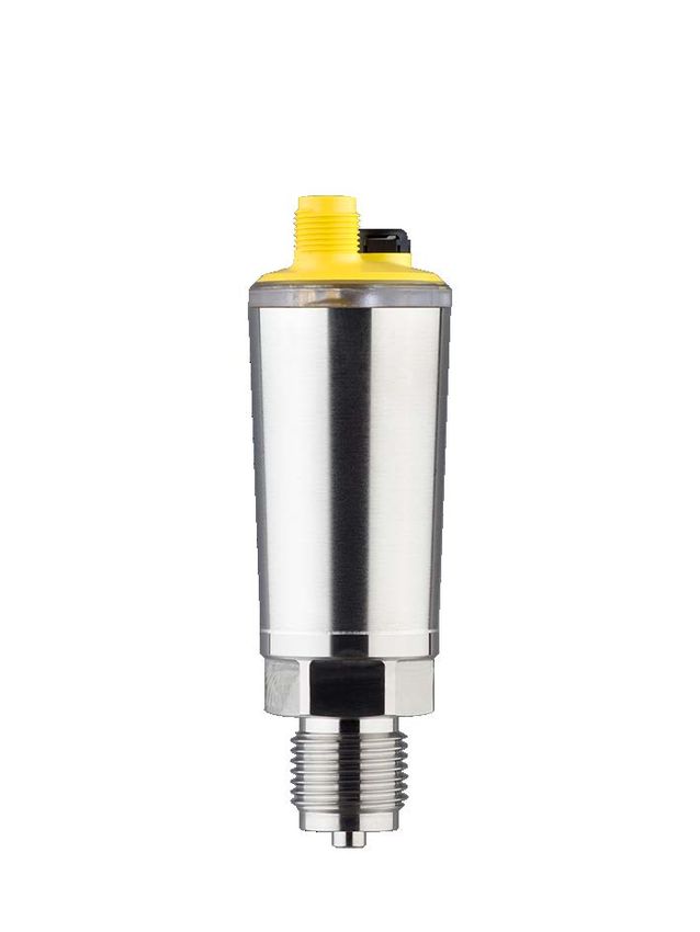
Contents

                       10.5 Software update.............................................................................................................. 33
                       10.6 How to proceed if a repair is necessary........................................................................... 34
                  11 Dismount................................................................................................................................. 35
                     11.1 Dismounting steps.......................................................................................................... 35
                     11.2 Disposal.......................................................................................................................... 35
                  12 Certificates and approvals..................................................................................................... 36
                     12.1 Radio licenses................................................................................................................. 36
                     12.2 Approvals for Ex areas.................................................................................................... 36
                     12.3 Approvals as overfill protection........................................................................................ 36
                     12.4 Food and pharmaceutical certificates.............................................................................. 36
                     12.5 EU conformity.................................................................................................................. 36
                     12.6 NAMUR recommendations............................................................................................. 36
                     12.7 Environment management system.................................................................................. 37
                  13 Supplement............................................................................................................................. 38
                     13.1 Technical data................................................................................................................. 38
                     13.2 Dimensions..................................................................................................................... 47
                     13.3 Industrial property rights.................................................................................................. 52
                     13.4 Licensing information for open source software.............................................................. 52
                     13.5 Trademark....................................................................................................................... 52
57087-EN-210301

                                                            Safety instructions for Ex areas
                                                            Take note of the Ex specific safety instructions for Ex applications.
                                                            These instructions are attached as documents to each instrument
                                                            with Ex approval and are part of the operating instructions.
                                                             Editing status: 2021-02-25

                  VEGABAR 29 • Two-wire 4 … 20 mA                                                                                                             3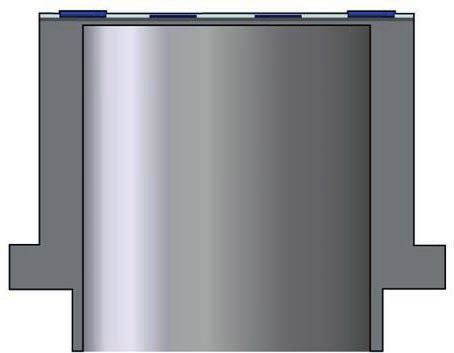
1 About this document

                            1     About this document
                            1.1    Function
                            This instruction provides all the information you need for mounting,
                            connection and setup as well as important instructions for mainte-
                            nance, fault rectification, the exchange of parts and the safety of the
                            user. Please read this information before putting the instrument into
                            operation and keep this manual accessible in the immediate vicinity
                            of the device.

                            1.2    Target group
                            This operating instructions manual is directed to trained personnel.
                            The contents of this manual must be made available to the qualified
                            personnel and implemented.

                            1.3    Symbols used
                            Document ID
                            This symbol on the front page of this instruction refers to the Docu-
                            ment ID. By entering the Document ID on www.vega.com you will
                            reach the document download.
                            Information, note, tip: This symbol indicates helpful additional infor-
                            mation and tips for successful work.
                            Note: This symbol indicates notes to prevent failures, malfunctions,
                            damage to devices or plants.
                            Caution: Non-observance of the information marked with this symbol
                            may result in personal injury.
                            Warning: Non-observance of the information marked with this symbol
                            may result in serious or fatal personal injury.
                            Danger: Non-observance of the information marked with this symbol
                            results in serious or fatal personal injury.
                            Ex applications
                            This symbol indicates special instructions for Ex applications.
                        •   List
                            The dot set in front indicates a list with no implied sequence.
                        1   Sequence of actions
                            Numbers set in front indicate successive steps in a procedure.
                            Battery disposal
                            This symbol indicates special information about the disposal of bat-
                            teries and accumulators.
                                                                                                      57087-EN-210301

4                                                                  VEGABAR 29 • Two-wire 4 … 20 mA
2 For your safety
2 For your safety
2.1 Authorised personnel
All operations described in this documentation must be carried out
only by trained, qualified personnel authorised by the plant operator.
During work on and with the device, the required personal protective
equipment must always be worn.
2.2 Appropriate use
The VEGABAR 29 is a pressure transmitter for process pressure and
hydrostatic level measurement.
You can find detailed information about the area of application in
chapter " Product description".
Operational reliability is ensured only if the instrument is properly
used according to the specifications in the operating instructions
manual as well as possible supplementary instructions.
2.3 Warning about incorrect use
Inappropriate or incorrect use of this product can give rise to applica-
tion-specific hazards, e.g. vessel overfill through incorrect mounting
or adjustment. Damage to property and persons or environmental
contamination can result. Also, the protective characteristics of the
instrument can be impaired.
2.4 General safety instructions
This is a state-of-the-art instrument complying with all prevailing
regulations and directives. The instrument must only be operated in a
technically flawless and reliable condition. The operator is responsi-
ble for the trouble-free operation of the instrument. When measuring
aggressive or corrosive media that can cause a dangerous situation
if the instrument malfunctions, the operator has to implement suitable
measures to make sure the instrument is functioning properly.
The safety instructions in this operating instructions manual, the na-
tional installation standards as well as the valid safety regulations and
accident prevention rules must be observed by the user.
For safety and warranty reasons, any invasive work on the device
beyond that described in the operating instructions manual may be
carried out only by personnel authorised by the manufacturer. Arbi-
trary conversions or modifications are explicitly forbidden. For safety
reasons, only the accessory specified by the manufacturer must be
used.
To avoid any danger, the safety approval markings and safety tips on
the device must also be observed.
57087-EN-210301
2.5 Installation and operation in the USA and
Canada
This information is only valid for USA and Canada. Hence the follow-
ing text is only available in the English language.
VEGABAR 29 • Two-wire 4 … 20 mA 52 For your safety
Installations in the US shall comply with the relevant requirements of
the National Electrical Code (ANSI/NFPA 70).
Installations in Canada shall comply with the relevant requirements of
the Canadian Electrical Code.
57087-EN-210301
6 VEGABAR 29 • Two-wire 4 … 20 mA3 Product description
3 Product description
3.1 Configuration
Scope of delivery The scope of delivery encompasses:
• VEGABAR 29 pressure transmitter
• Information sheet " Documents and software" with:
–– Instrument serial number
–– QR code with link for direct scanning
• Information sheet " PINs and Codes" (with Bluetooth versions)
with:
–– Bluetooth access code
• Information sheet " Access protection" (with Bluetooth versions)
with:
–– Bluetooth access code
–– Emergency Bluetooth unlock code
–– Emergency device code
The further scope of delivery encompasses:
• Documentation
–– Quick setup guide VEGABAR 29
–– Ex-specific " Safety instructions" (with Ex versions)
–– Radio approvals (versions with Bluetooth)
–– If necessary, further certificates
Note:
Optional instrument features are also described in this operating
instructions manual. The respective scope of delivery results from the
order specification.
Scope of this operating This operating instructions manual applies to the following instrument
instructions versions:
• Hardware version from 1.0.0
• Software version from 1.3.0
57087-EN-210301
VEGABAR 29 • Two-wire 4 … 20 mA 73 Product description
Constituent parts
5
4
3
2
1
Fig. 1: Components of VEGABAR 29
1 Process fitting
2 Electronics housing
3 LED illuminated ring
4 Ventilation/pressure compensation
5 Plug connector
Type label The type label contains the most important data for identification and
use of the instrument.
1 PP - 222 329 22B s/n 12345678
0044
2
12V...35V
4...20mA
IP66/IP67/69, TYPE 6P
3 MWP 33bar (3300kPa)
0...2,5bar (0...250kPa) rel
AL203, FKM, 316L
+
2019
2 1 www.vega.com
D-77761 SCHILTACH,
6
4 3 4
- Made in Germany
5 123456
Fig. 2: Layout of the type label (example)
1 Order/Serial number
2 Field for approvals
3 Technical data
4 Assignment
57087-EN-210301
5 Bluetooth access code
6 QR code for device documentation
Documents and software Move to " www.vega.com" and enter in the search field the serial
number of your instrument.
8 VEGABAR 29 • Two-wire 4 … 20 mA3 Product description
There you can find the following information about the instrument:
• Order data
• Documentation
• Software
Alternatively, you can find all via your smartphone:
• Scan the QR-code on the type label of the device or
• Enter serial number manually in the VEGA Tools app (available
free of charge in the respective stores)
3.2 Principle of operation
Application area VEGABAR 29 is suitable for applications in virtually all industries. It is
used for the measurement of the following pressure types.
• Gauge pressure
• Absolute pressure
• Vacuum
Measured products Measured products are gases, vapours and liquids.
The device is especially suitable for applications with higher tempera-
tures and high pressures.
Measured variables The VEGABAR 29 is suitable for the measurement of the following
process variables:
• Process pressure
• Level
Fig. 3: Process pressure measurement VEGABAR 29
Measuring system The process pressure acts on the sensor element via the process dia-
phragm. The process pressure causes a resistance change which is
converted into a corresponding output signal and output as measured
value.
57087-EN-210301
Piezoresistive sensor element
Measuring ranges up to 100 bar: piezoresistive sensor element with
internal transmission liquid is used.
VEGABAR 29 • Two-wire 4 … 20 mA 93 Product description
1 2
3 4
Fig. 4: Configuration of the measuring system with piezoresistive sensor ele-
ment
1 Sensor element
2 Base element
3 Transmission liquid
4 Process diaphragm
Strain gauge (DMS) sensor element
For measuring ranges above 250 bar, a strain gauge (DMS) sensor
element (dry system) is used.
1
2
3
Fig. 5: Configuration of the measuring system with strain gauge (DMS) sensor
element
1 Sensor element
2 Process diaphragm
3 Pressure cylinder
Pressure types Relative pressure: the measuring cell is open to the atmosphere.
The ambient pressure is detected in the measuring cell and compen-
sated. It thus has no influence on the measured value.
Absolute pressure: the measuring cell contains vacuum and is
encapsulated. The ambient pressure is not compensated and does
hence influence the measured value.
Seal concept The measuring system is completely welded and thus sealed against
the process.
The process fitting is sealed against the process by a suitable seal. It
must be provided by the customer, depending on the process fitting
57087-EN-210301
also included in the scope of delivery, see chapter " Technical data", "
Materials and weights".
10 VEGABAR 29 • Two-wire 4 … 20 mA3 Product description
3.3 Adjustment
Wireless adjustment Devices with integrated Bluetooth module can be adjusted wirelessly
via standard adjustment tools: 1)
• Smartphone/tablet (iOS or Android operating system)
• PC/notebook (Windows operating system)
2
1
3
Fig. 6: Wireless connection to standard adjustment tools with integrated
Bluetooth LE
1 Sensor
2 Smartphone/Tablet
3 Bluetooth USB adapter
3.4 Packaging, transport and storage
Packaging Your instrument was protected by packaging during transport. Its
capacity to handle normal loads during transport is assured by a test
based on ISO 4180.
The packaging consists of environment-friendly, recyclable card-
board. For special versions, PE foam or PE foil is also used. Dispose
of the packaging material via specialised recycling companies.
Transport Transport must be carried out in due consideration of the notes on the
transport packaging. Nonobservance of these instructions can cause
damage to the device.
Transport inspection The delivery must be checked for completeness and possible transit
damage immediately at receipt. Ascertained transit damage or con-
cealed defects must be appropriately dealt with.
Storage Up to the time of installation, the packages must be left closed and
stored according to the orientation and storage markings on the
outside.
57087-EN-210301
Unless otherwise indicated, the packages must be stored only under
the following conditions:
1)
Reduced effective range with M12 x 1 plug stainless steel (closed metal
housing), see chapter "Technical Data"
VEGABAR 29 • Two-wire 4 … 20 mA 113 Product description
• Not in the open
• Dry and dust free
• Not exposed to corrosive media
• Protected against solar radiation
• Avoiding mechanical shock and vibration
Storage and transport • Storage and transport temperature see chapter " Supplement -
temperature Technical data - Ambient conditions"
• Relative humidity 20 … 85 %
3.5 Accessories
The instructions for the listed accessories can be found in the down-
load area on our homepage.
Welded sockets and Welded sockets are used to connect the devices to the process.
adapters Threaded adapters enable simple adaptation of devices with stand-
ard threaded fittings, e.g. to process-side hygiene connections.
Mounting accessories The suitable mounting accessories for VEGABAR 29 includes si-
phons, blocking valves and measuring instrument holders.
57087-EN-210301
12 VEGABAR 29 • Two-wire 4 … 20 mA4 Mounting
4 Mounting
4.1 General instructions
Ambient conditions The instrument is suitable for standard and extended ambient condi-
tions acc. to DIN/EN/IEC/ANSI/ISA/UL/CSA 61010-1. It can be used
indoors as well as outdoors.
Process conditions Note:
For safety reasons, the instrument must only be operated within the
permissible process conditions. You can find detailed information on
the process conditions in chapter " Technical data" of the operating
instructions or on the type label.
Hence make sure before mounting that all parts of the instrument ex-
posed to the process are suitable for the existing process conditions.
These are mainly:
• Active measuring component
• Process fitting
• Process seal
Process conditions in particular are:
• Process pressure
• Process temperature
• Chemical properties of the medium
• Abrasion and mechanical influences
Permissible process The permissible process pressure range is specified by "MWP" (Maxi-
pressure (MWP) - Device mum Working Pressure) on the type label, see chapter " Structure".
The MWP takes the element of the measuring cell and processing
fitting combination with the weakest pressure into consideration and
may applied permanently. The specification refers to a reference
temperature of +20 °C (+68 °F). It also applies when a measuring cell
with a higher measuring range than the permissible pressure range of
the process fitting is installed order-related.
In order to prevent damage to the device, a test pressure may only
exceed the specified MWP briefly by 1.5 times at reference tempera-
ture. The pressure stage of the process fitting as well as the overload
resistance of the measuring cell are taken into consideration here
(see chapter " Technical Data").
In addition, a temperature derating of the process fitting, e. g. with
flanges, can limit the permissible process pressure range according
to the respective standard.
Protection against mois- Protect your instrument against moisture ingress through the following
ture measures:
• Use a suitable connection cable (see chapter " Connecting to
57087-EN-210301
power supply")
• Tighten the cable gland or plug connector
• Lead the connection cable downward in front of the cable entry or
plug connector
VEGABAR 29 • Two-wire 4 … 20 mA 134 Mounting
This applies mainly to outdoor installations, in areas where high
humidity is expected (e.g. through cleaning processes) and on cooled
or heated vessels.
Ventilation and pressure Ventilation and pressure compensation for VEGABAR 29 are provided
compensation by an air-permeable, moisture-blocking filter element.
1
Fig. 7: Position of the filter element
1 Filter element
For effective ventilation, the filter element must always be free of
buildup.
Screwing in Devices with threaded fitting are screwed into the process fitting with
a suitable wrench via the hexagon.
See chapter " Dimensions" for wrench size.
Warning:
The housing or the electrical connection may not be used for screw-
ing in! Depending on the device version, tightening can cause dam-
age, e. g. to the rotation mechanism of the housing.
Permissible process The permissible process pressure range is stated on the type label.
pressure (MWP) - Mount- The instrument should only be operated with these pressures if the
ing accessory mounting accessory used also fulfils these values. This should be en-
sured by suitable flanges, welded sockets, tension rings with Clamp
connections, sealings, etc.
Temperature limits Higher process temperatures often mean also higher ambient
temperatures. Make sure that the upper temperature limits stated in
chapter " Technical data" for the environment of the electronics hous-
ing and connection cable are not exceeded.
2
1
57087-EN-210301
Fig. 8: Temperature ranges
1 Process temperature
2 Ambient temperature
14 VEGABAR 29 • Two-wire 4 … 20 mA4 Mounting
4.2 Process pressure measurement
In gases Keep the following in mind when setting up the measuring system:
• Mount the instrument above the measuring point
Possible condensation can then drain off into the process line.
1
2
3
Fig. 9: Measurement setup for process pressure measurement of gases in
pipelines
1 VEGABAR 29
2 Blocking valve
3 Pipeline
In vapours Keep the following in mind when setting up the measuring system:
• Connect via a siphon
1 1
2 2
3 3
4 4
Fig. 10: Measurement setup for process pressure measurement of gases in
pipelines
57087-EN-210301
1 VEGABAR 29
2 Blocking valve
3 Siphon in U or circular form
4 Pipeline
VEGABAR 29 • Two-wire 4 … 20 mA 154 Mounting
A protective accumulation of water is formed through condensation
in the pipe bends. Even in applications with hot steam, a medium
temperature < 100 °C on the transmitter is ensured.
In liquids Keep the following in mind when setting up the measuring system:
• Mount the instrument below the measuring point
The effective pressure line is always filled with liquid and gas bubbles
can bubble up to the process line.
3
2
1
Fig. 11: Measurement setup for process pressure measurement of liquids in
pipelines
1 VEGABAR 29
2 Blocking valve
3 Pipeline
4.3 Level measurement
Measurement setup Keep the following in mind when setting up the measuring system:
• Mount the instrument below the min. level
• Do not mount the instrument close to the filling stream or emptying
area
• Mount the instrument so that it is protected against pressure
shocks from the stirrer
57087-EN-210301
Fig. 12: Measurement setup for level measurement
16 VEGABAR 29 • Two-wire 4 … 20 mA5 Connecting to power supply
5 Connecting to power supply
5.1 Preparing the connection
Safety instructions Always keep in mind the following safety instructions:
• Carry out electrical connection by trained, qualified personnel
authorised by the plant operator
• If overvoltage surges are expected, overvoltage arresters should
be installed
Warning:
Only connect or disconnect in de-energized state.
Voltage supply The data for power supply are specified in chapter " Technical data".
Note:
Power the instrument via an energy-limited circuit (power max. 100 W)
acc. to IEC 61010-1, e.g.
• Class 2 power supply unit (acc. to UL1310)
• SELV power supply unit (safety extra-low voltage) with suitable
internal or external limitation of the output current
Keep in mind the following additional factors that influence the operat-
ing voltage:
• Lower output voltage of the power supply unit under nominal load
(e.g. with a sensor current of 20.5 mA or 22 mA in case of fault)
• Influence of additional instruments in the circuit (see load values in
chapter " Technical data")
Connection cable Use cable with round cross section. Depending on the plug connec-
tion, you have to select the outer diameter of the cable respectively so
that the seal effect of the cable gland is ensured.
Depending on the connection method or signal output, the device is
connected with standard two, three or four-wire cable without shield-
ing.
5.2 Connection procedure
M12 x 1 plug This plug connection requires a complete confectioned cable with
counter plug.
Plug according to Proceed as follows:
ISO 4400 1. Loosen the screw on the rear of the plug connector
2. Remove the plug connector and seal from VEGABAR 29
3. Remove the plug insert from the plug housing
57087-EN-210301
VEGABAR 29 • Two-wire 4 … 20 mA 175 Connecting to power supply
1
3
2
Fig. 13: Loosen the plug insert
1 Cable gland
2 Plug insert
3 Plug housing
4. Remove approx. 5 cm of the cable mantle, strip approx. 1 cm
insulation from the individual wires
5. Lead the cable through the cable gland into the plug housing
6. Connect the wire ends to the screw terminals according to the
wiring plan
2
1
3
4
Fig. 14: Connection to the screw terminals
1 Cable gland
2 Plug housing
3 Plug insert
4 Plug seal
7. Snap the plug insert into the plug housing and insert the sensor
seal
8. Plug the plug insert with seal to VEGABAR 29 and tighten the
screw
The electrical connection is finished.
ISO 4400 plug with Proceed as follows:
hinged cover 1. Loosen the screw in the cover of the plug connector
57087-EN-210301
2. Open the cover and remove it
3. Press the plug insert downwards
4. Loosen the screws of the strain relief and cable entry
18 VEGABAR 29 • Two-wire 4 … 20 mA5 Connecting to power supply
1 2 3
1
3
2
4
Fig. 15: Loosen the plug insert
1 Plug insert
2 Strain relief
3 Cable gland
4 Plug housing
5. Remove approx. 5 cm of the cable mantle, strip approx. 1 cm
insulation from the individual wires
6. Lead the cable through the cable gland into the plug housing
7. Connect the wire ends to the screw terminals according to the
wiring plan
2
1
3
4
5
Fig. 16: Connection to the screw terminals
1 Cable gland
2 Cover
3 Plug housing
4 Plug insert
5 Plug seal
8. Snap the plug insert into the plug housing and insert the sensor
seal
Information:
Note the correct arrangement, see illustration
9. Tighten the screws on the strain relief and cable entry
57087-EN-210301
10. Hook in the cover and push onto the plug connection, tighten
cover screw
11. Plug the plug insert with seal to VEGABAR 29 and tighten the
screw
VEGABAR 29 • Two-wire 4 … 20 mA 195 Connecting to power supply
The electrical connection is finished.
Plug according to For this plug version you can use standard cable with round wire
ISO 4400 with IDC cross-section. The inner conductors do not have to be stripped. The
method of termination plug connects the conductors automatically when screwing in. Cable
diameter 5.5 … 8 mm, protection IP67.
5
1 2 3 4
Fig. 17: Connection, valve plug ISO 4400 with IDC crimping technology
1 Compression nut
2 Cable
3 Seal ring
4 Terminal insert
5 Plug housing
5.3 Wiring plan
M12 x 1 plug
+
2 1
1
3 4
-
Fig. 18: Wiring plan - two-wire 4 … 20 mA - M12 x 1 plug
1 Voltage supply and signal output
Contact, plug connector Function/Polarity
1 Voltage supply, signal output/Plus
2 Voltage supply, signal output/Minus
3 Voltage supply, signal output/Minus
4 Free
Note:
57087-EN-210301
Contacts 2 and 3 are internally bridged from delivery status approx.
week 17/2021. The negative supply can thus be made either on
contact 2 or 3.
20 VEGABAR 29 • Two-wire 4 … 20 mA5 Connecting to power supply
Plug according to
ISO 4400 +
1 2 1
3
-
Fig. 19: Wiring plan - two-wire 4 … 20 mA - plug according to ISO 4400
1 Voltage supply and signal output
Contact, plug connector Function/Polarity
1 Voltage supply, signal output/+
2 Voltage supply, signal output/-
3 Free
Electrically connected with metal housing
Direct cable outlet
2
1
Fig. 20: Wiring plan - Two-wire 4 … 20 mA - direct cable outlet
1 Voltage supply, signal output
2 Ventilation
Wire colour Function/Polarity
Brown Voltage supply, signal output/Plus
Blue Voltage supply, signal output/Minus
5.4 Switch-on phase
After switching on, the device first carries out a self-check:
• Internal check of the electronics
• The output signal jumps to the set fault current
The current measured value is then output on the signal cable.
57087-EN-210301
VEGABAR 29 • Two-wire 4 … 20 mA 216 Access protection
6 Access protection
6.1 Bluetooth radio interface
Devices with a Bluetooth radio interface are protected against un-
wanted access from outside. This means that only authorized persons
can receive measured and status values and change device settings
via this interface.
Bluetooth access code A Bluetooth access code is required to establish Bluetooth com-
munication via the adjustment tool (smartphone/tablet/notebook).
This code must be entered once when Bluetooth communication is
established for the first time in the adjustment tool. It is then stored in
the adjustment tool and does not have to be entered again.
The Bluetooth access code is individual for each device. It is printed
on the device housing and is also supplied with the device in the infor-
mation sheet " PINs and Codes". It can be changed by the user after
the first connection has been established. If the Bluetooth access
code has not been entered correctly, a new entry can only be made
after a waiting period has elapsed. The waiting time increases with
each additional incorrect entry.
Emergency Bluetooth The emergency Bluetooth access code enables Bluetooth communi-
unlock code cation to be established in the event that the Bluetooth access code
is no longer known. It can't be changed. The emergency Bluetooth
access code can be found in information sheet " Access protection".
If this document is lost, the emergency Bluetooth access code can
be retrieved from your personal contact person after legitimation.
The storage and transmission of Bluetooth access codes is always
encrypted (SHA 256 algorithm).
6.2 Protection of the parameterization
The settings (parameters) of the device can be protected against un-
wanted changes. The parameter protection is deactivated on delivery,
all settings can be made.
Device code To protect the parameterization, the device can be locked by the user
with the aid of a freely selectable device code. The settings (param-
eters) can then only be read out, but not changed. The device code
is also stored in the adjustment tool. However, unlike the Bluetooth
access code, it must be re-entered for each unlock. When using the
adjustment app or DTM, the stored device code is then suggested to
the user for unlocking.
Emergency device code The emergency device code allows unlocking the device in case the
device code is no longer known. It can't be changed. The emergency
device code can also be found on the supplied information sheet " Ac-
57087-EN-210301
cess protection". If this document is lost, the emergency device code
can be retrieved from your personal contact person after legitimation.
The storage and transmission of the device codes is always encrypt-
ed (SHA 256 algorithm).
22 VEGABAR 29 • Two-wire 4 … 20 mA6 Access protection
6.3 Storing the codes in myVEGA
If the user has a " myVEGA" account, then the Bluetooth access code
as well as the device code are additionally stored in his account under
" PINs and Codes". This greatly simplifies the use of additional adjust-
ment tools, as all Bluetooth access and device codes are automati-
cally synchronized when connected to the " myVEGA" account
57087-EN-210301
VEGABAR 29 • Two-wire 4 … 20 mA 237 Setup with smartphone/tablet (Bluetooth)
7 Setup with smartphone/tablet (Bluetooth)
7.1 Preparations
System requirements Make sure that your smartphone/tablet meets the following system
requirements:
• Operating system: iOS 8 or newer
• Operating system: Android 5.1 or newer
• Bluetooth 4.0 LE or newer
Download the VEGA Tools app from the " Apple App Store", " Goog-
le Play Store" or " Baidu Store" to your smartphone or tablet.
7.2 Connecting
Connecting Start the adjustment app and select the function " Setup". The smart-
phone/tablet searches automatically for Bluetooth-capable instru-
ments in the area.
The message " Connecting …" is displayed.
The devices found are listed and the search is automatically contin-
ued.
Select the requested instrument in the device list.
As soon as the Bluetooth connection to a device is established, the
LED display of the device in question flashes blue 4 times.
Authenticate When establishing the connection for the first time, the operating tool
and the sensor must authenticate each other. After the first correct
authentication, each subsequent connection is made without a new
authentication query.
Enter Bluetooth access For authentication, enter the 6-digit Bluetooth access code in the
code next menu window. You can find the code on the outside of the device
housing and on the information sheet " Pins and Codes" in the device
packaging.
Fig. 21: Enter Bluetooth access code
Note:
If an incorrect code is entered, the code can only be entered again
after a delay time. This time gets longer after each incorrect entry.
57087-EN-210301
The message " Waiting for authentication" is displayed on the smart-
phone/tablet.
Connected After connection, the sensor adjustment menu is displayed on the
respective adjustment tool.
24 VEGABAR 29 • Two-wire 4 … 20 mA7 Setup with smartphone/tablet (Bluetooth)
If the Bluetooth connection is interrupted, e.g. due to a too large
distance between the two devices, this is displayed on the adjustment
tool. The message disappears when the connection is restored.
Change device code Parameter adjustment of the device is only possible if the parameter
protection is deactivated. When delivered, parameter protection is
deactivated by default and can be activated at any time.
It is recommended to enter a personal 6-digit device code. To do this,
go to menu " Extended functions", " Access protection", menu item "
Protection of the parameter adjustment".
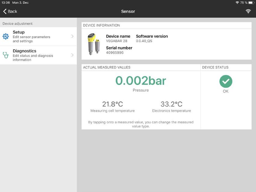
7.3 Sensor parameter adjustment
Enter parameters The sensor adjustment menu is divided into two halves:
On the left you'll find the navigation section with the menus " Setup", "
Display", " Diagnosis" and others.
The selected menu item, recognisable by the colour change, is dis-
played in the right half.
Fig. 22: Example of an app view - Setup measured values
57087-EN-210301
VEGABAR 29 • Two-wire 4 … 20 mA 258 Setup with PC/notebook (Bluetooth)
8 Setup with PC/notebook (Bluetooth)
8.1 Preparations
System requirements Make sure that your PC/notebook meets the following system require-
ments:
• Operating system Windows 10
• DTM Collection 10/2020 or newer
• Bluetooth 4.0 LE or newer
Activate Bluetooth con- Activate the Bluetooth connection via the project assistant.
nection
Note:
Older systems do not always have an integrated Bluetooth LE. In
these cases, a Bluetooth USB adapter is required. Activate the
Bluetooth USB adapter using the Project Wizard.
After activating the integrated Bluetooth or the Bluetooth USB adapt-
er, devices with Bluetooth are found and created in the project tree.
8.2 Connecting
Connecting Select the requested device for the online parameter adjustment in
the project tree.
As soon as the Bluetooth connection to a device is established, the
LED display of the device in question flashes blue 4 times.
Authenticate When establishing the connection for the first time, the operating tool
and the device must authenticate each other. After the first correct
authentication, each subsequent connection is made without a new
authentication query.
Enter Bluetooth access For authentication, enter in the next menu window the 6-digit
code Bluetooth access code:
57087-EN-210301
Fig. 23: Enter Bluetooth access code
26 VEGABAR 29 • Two-wire 4 … 20 mA8 Setup with PC/notebook (Bluetooth)
You can find the code on the outside of the device housing and on the
information sheet " PINs and Codes" in the device packaging.
Note:
If an incorrect code is entered, the code can only be entered again
after a delay time. This time gets longer after each incorrect entry.
The message " Waiting for authentication" is displayed on the PC/
notebook.
Connected After connection, the device DTM appears.
If the connection is interrupted, e.g. due to a too large distance be-
tween device and adjustment tool, this is displayed on the adjustment
tool. The message disappears when the connection is restored.
Change device code Parameter adjustment of the device is only possible if the parameter
protection is deactivated. When delivered, parameter protection is
deactivated by default and can be activated at any time.
It is recommended to enter a personal 6-digit device code. To do this,
go to menu " Extended functions", " Access protection", menu item "
Protection of the parameter adjustment".
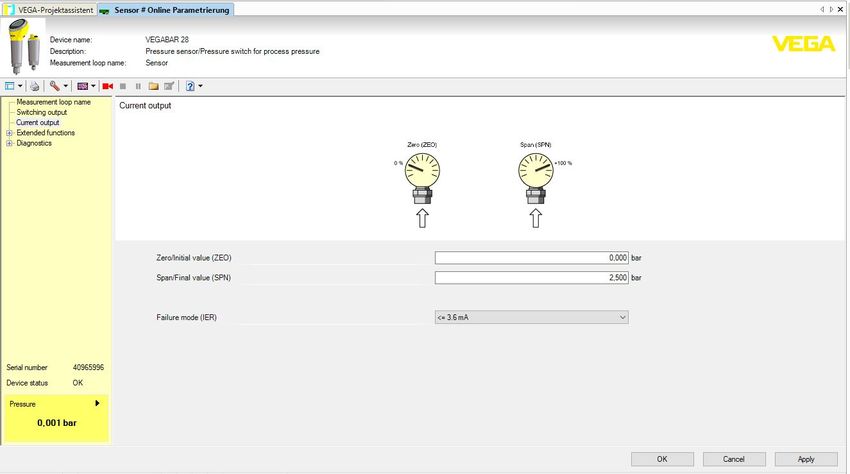
8.3 Parameter adjustment
Prerequisites For parameter adjustment of the instrument via a Windows PC, the
configuration software PACTware and a suitable instrument driver
(DTM) according to FDT standard are required. The latest PACTware
version as well as all available DTMs are compiled in a DTM Collec-
tion. The DTMs can also be integrated into other frame applications
according to FDT standard.
Fig. 24: Example of a DTM view - Adjustment current output
57087-EN-210301
VEGABAR 29 • Two-wire 4 … 20 mA 279 Menu overview
9 Menu overview
9.1 VEGA Tools app and DTM (Bluetooth)
Start image (app)
Menu item Device information Actual measured values Device status
Start image Device name, software ver- Pressure, output current, measur- OK, error indication
sion, serial number ing cell temperature, electronics
temperature, sensor TAG
Main menu
Menu item Parameter (code acc. to VD- Editing section Basic setting
MA 24574-1)
Measurement loop name Measurement loop name 19 alphanumeric characters/ Sensor
special characters
Current output Zero 4 mA (ZEO) Measuring
Measuring range begin … range begin
Span 20 mA (SPN) measuring range end Measuring
range end
Reaction in case of fault (FER) ≤ 3.6 mA, ≥ 21 mA ≤ 3.6 mA
360° status display (free Brightness (LED) 0 %, 10 %, 20 … 100 % 100 %
signalling)
Signalling Acc. to NAMUR NE 107, free Switching out-
signalling put
Fault Red, yellow …, individual colour Yellow
selection, no signalling
Flashing Yes, no No
Operating states Operating states 1, 2, 3, 4, 5 1
Upper limit Measuring range begin …
measuring range end
Colour selection Red, yellow …, individual colour Yellow
selection, no signalling
Flashing Yes, no No
Extended functions
Menu item Parameter (code acc. to VD- Editing section Basic setting
MA 24574-1)
Damping Damping (DAM) 0 … 9.999 s 0s
Activate thermo-shock sup- Yes, no No
pression
Offset correction Offset correction (OFS) Execute, automatic correction 0,000 bar
Adjustment with medium Apply min. pressure on the sen-
Accept 4 mA (LRV)
sor
57087-EN-210301
-
Apply max. pressure on the
Accept 20 mA (URV)
sensor
28 VEGABAR 29 • Two-wire 4 … 20 mA9 Menu overview
Menu item Parameter (code acc. to VD- Editing section Basic setting
MA 24574-1)
Units Pressure unit (UNI) mbar, bar, Pa, kPa, MPa, psi, bar
mmH2O, mmHg, inH2O, inHg
Temperature (TMP) °C, °F °C
Access protection Bluetooth access code Device-specific
access code
Protection of the parameteri- Deactivated
zation
Reset Reset -
Diagnostics
Menu item Parameter Indication
Status Device status, parameter change Actual values
counter
Peak value indicator Process pressure, measuring cell Acutal values, min. values, max.
temperature, electronics temper- values
ature
Measured values Measured values, output, additional Actual values pressure, current
measured values output, electronics temperature,
measuring cell temperature
Measured value memory (DTM) Trend curve Last values
Simulation Pressure, current output Simulated values
Sensor information Device name, serial number, hard-
ware version, software version,
factory calibration date, Device Re-
vision, measuring range begin,
measuring range end
Sensor features (DTM) Sensor characteristics Features of the instrument version
57087-EN-210301
VEGABAR 29 • Two-wire 4 … 20 mA 2910 Diagnostics and servicing
10 Diagnostics and servicing
10.1 Maintenance
Precaution measures In some applications, product buildup on the diaphragm can influence
against buildup the measuring result. Depending on the sensor and application, take
precautions to ensure that heavy buildup, and especially a hardening
thereof, is avoided.
Cleaning The cleaning helps that the type label and markings on the instrument
are visible.
Take note of the following:
• Use only cleaning agents which do not corrode the housings, type
label and seals
• Use only cleaning methods corresponding to the housing protec-
tion rating
10.2 Rectify faults
Reaction when malfunc- The operator of the system is responsible for taking suitable meas-
tion occurs ures to rectify faults.
Causes of malfunction The device offers maximum reliability. Nevertheless, faults can occur
during operation. These may be caused by the following, e.g.:
• Sensor
• Process
• Voltage supply
• Signal processing
Fault rectification The first measures are:
• Evaluation of fault messages
• Checking the output signal
• Treatment of measurement errors
A smartphone/tablet with the adjustment app or a PC/notebook with
the software PACTware and the suitable DTM offer you further com-
prehensive diagnostic possibilities. In many cases, the causes can be
determined in this way and the faults eliminated.
Reaction after fault recti- Depending on the reason for the fault and the measures taken, the
fication steps described in chapter " Setup" must be carried out again or must
be checked for plausibility and completeness.
24 hour service hotline Should these measures not be successful, please call in urgent cases
the VEGA service hotline under the phone no. +49 1805 858550.
The hotline is also available outside normal working hours, seven
days a week around the clock.
57087-EN-210301
Since we offer this service worldwide, the support is provided in
English. The service itself is free of charge, the only costs involved are
the normal call charges.
30 VEGABAR 29 • Two-wire 4 … 20 mA10 Diagnostics and servicing
10.3 Diagnosis, fault messages
4 … 20 mA signal Connect a multimeter in the suitable measuring range according to
the wiring plan. The following table describes possible errors in the
current signal and helps to eliminate them:
Error Cause Rectification
4 … 20 mA signal not stable Fluctuating measured value Set damping
4 … 20 mA signal missing Electrical connection faulty Check connection, correct, if necessary
Voltage supply missing Check cables for breaks; repair if nec-
essary
Operating voltage too low, load resist- Check, adapt if necessary
ance too high
Current signal greater than Sensor electronics defective Replace device or send in for repair de-
22 mA, less than 3.6 mA pending on device version
LED illuminated ring The LED illuminated ring on the device (see chapter " Configuration")
indicates the status of the device. This enables simple on-site diagno-
sis without the need for tools.
Note:
The LED illuminated ring is not available for device versions with
continuous stainless steel housing.
Colour 2) Permanent light Flashing
Green voltage supply on, operation without failure Message " Maintenance required" is dis-
played
Yellow voltage supply on, operation without failure -
Red voltage supply on, operation with failure Message acc. to to NE 107 " Function
check", " Out of specification" or " Simula-
tion state" is displayed
10.4 Status messages according to NE 107
The instrument features self-monitoring and diagnostics according
to NE 107 and VDI/VDE 2650. In addition to the status messages in
the following tables there are more detailed error messages available
under the menu item " Diagnostics" via the respective adjustment
module.
Status messages The status messages are divided into the following categories:
• Failure
• Function check
• Out of specification
• Maintenance required
and explained by pictographs:
57087-EN-210301
2)
Adjustable via VEGA Tools app or PACTware/DTM
VEGABAR 29 • Two-wire 4 … 20 mA 3110 Diagnostics and servicing
1 2 3 4
Fig. 25: Pictographs of the status messages
1 Failure - red
2 Out of specification - yellow
3 Function check - orange
4 Maintenance required - blue
Failure: Due to a malfunction in the instrument, a fault message is
output.
This status message is always active. It cannot be deactivated by the
user.
Function check: The instrument is being worked on, the measured
value is temporarily invalid (for example during simulation).
This status message is inactive by default.
Out of specification: The measured value is unreliable because an
instrument specification was exceeded (e.g. electronics temperature).
This status message is inactive by default.
Maintenance required: Due to external influences, the instrument
function is limited. The measurement is affected, but the measured
value is still valid. Plan in maintenance for the instrument because a
failure is expected in the near future (e.g. due to buildup).
This status message is inactive by default.
Failure
Code Cause Rectification
Text message
F013 Hardware error in the area of the meas- Send instrument for repair
no measured value available uring cell
F017 Adjustment not within specification Change adjustment
Adjustment span too small
F036 Failed or interrupted software update Repeat software update
no operable sensor software
F080 General software error Restart
General software error
F110 Selected switching points too close to- Increase the distance between the
Switching points too close to- gether switching points
gether
F111 Switching point 1 is smaller than switch- Select switching point 1 to greater than
57087-EN-210301
Switching points inter- ing point 2 switching point 2
changed
F260 Checksum error in the calibration val- Send instrument for repair
Error in the calibration ues
32 VEGABAR 29 • Two-wire 4 … 20 mA10 Diagnostics and servicing
Code Cause Rectification
Text message
F261 Checksum error in the configuration Carry out a reset
Error in the instrument set- values
tings
Function check
Code Cause Rectification
Text message
C700 A simulation is active Finish simulation
Simulation active Wait for the automatic end after
60 mins.
Out of specification
Code Cause Rectification
Text message
S600 Temperature of the electronics in the Check ambient temperature
Impermissible electronics non-specified range Insulate electronics
temperature
S604 Overload or short circuit at output 1 or 2 Electrical connection, check load re-
Switching output overloaded sistance
Maintenance
Code Cause Rectification
Text message
M504 Interference of the internal communica- Restart
Error at a device interface tion to Bluetooth Send instrument for repair
M510 Fault in internal communication with the Restart
No communication with the display Send instrument for repair
main controller
10.5 Software update
The device software is updated via Bluetooth.
The following components are required:
• Instrument
• Voltage supply
• PC/notebook with PACTware/DTM and Bluetooth USB adapter
• Current instrument software as file
You can find the current instrument software as well as detailed infor-
mation on the procedure in the download area of our homepage.
57087-EN-210301
Caution:
Instruments with approvals can be bound to certain software versions.
Therefore make sure that the approval is still effective after a software
update is carried out.
VEGABAR 29 • Two-wire 4 … 20 mA 3310 Diagnostics and servicing
You can find detailed information in the download area on our home-
page.
10.6 How to proceed if a repair is necessary
You can find an instrument return form as well as detailed information
about the procedure in the download area of our homepage. By doing
this you help us carry out the repair quickly and without having to call
back for needed information.
In case of repair, proceed as follows:
• Print and fill out one form per instrument
• Clean the instrument and pack it damage-proof
• Attach the completed form and, if need be, also a safety data
sheet outside on the packaging
• Ask the agency serving you to get the address for the return ship-
ment. You can find the agency on our homepage.
57087-EN-210301
34 VEGABAR 29 • Two-wire 4 … 20 mA11 Dismount
11 Dismount
11.1 Dismounting steps
Warning:
Before dismounting, be aware of dangerous process conditions such
as e.g. pressure in the vessel or pipeline, high temperatures, cor-
rosive or toxic media etc.
Take note of chapters " Mounting" and " Connecting to voltage sup-
ply" and carry out the listed steps in reverse order.
11.2 Disposal
The device is made of recyclable materials. For this reason, it should
be disposed of by a specialist recycling company. Observe the ap-
plicable national regulations.
57087-EN-210301
VEGABAR 29 • Two-wire 4 … 20 mA 3512 Certificates and approvals
12 Certificates and approvals
12.1 Radio licenses
Bluetooth
The Bluetooth radio module in the device has been tested and
approved according to the current edition of the applicable country-
specific norms or standards.
The confirmations as well as regulations for use can be found in the
document " Radio licenses" supplied or on our homepage.
12.2 Approvals for Ex areas
Approved versions for use in hazardous areas are available or in
preparation for the device series.
You can find the relevant documents on our homepage.
12.3 Approvals as overfill protection
Approved versions for use as part of an overfill protection system are
available or in preparation for this device series.
The corresponding approvals can be found on our homepage.
12.4 Food and pharmaceutical certificates
Versions for use in the food and pharmaceutical industries are avail-
able or in preparation.
The corresponding certificates can be found on our homepage.
12.5 EU conformity
The device fulfils the legal requirements of the applicable EU direc-
tives. By affixing the CE marking, we confirm the conformity of the
instrument with these directives.
The EU conformity declaration can be found on our homepage.
Due to the design of its process fittings, the device does not subject
of EU pressure device directive if it is operated at process pressures
≤ 200 bar. 3)
12.6 NAMUR recommendations
NAMUR is the automation technology user association in the process
industry in Germany. The published NAMUR recommendations are
accepted as the standard in field instrumentation.
The device fulfils the requirements of the following NAMUR recom-
mendations:
• NE 21 – Electromagnetic compatibility of equipment
•
57087-EN-210301
NE 43 – Signal level for fault information from measuring transduc-
ers
3)
Exception: Versions with measuring ranges from 250 bar. These are subject
of the EU Pressure Device Directive.
36 VEGABAR 29 • Two-wire 4 … 20 mA12 Certificates and approvals
• NE 53 – Compatibility of field devices and display/adjustment
components
• NE 107 – Self-monitoring and diagnosis of field devices
For further information see www.namur.de.
12.7 Environment management system
Protection of the environment is one of our most important duties.
That is why we have introduced an environment management system
with the goal of continuously improving company environmental pro-
tection. The environment management system is certified according
to DIN EN ISO 14001. Please help us fulfil this obligation by observ-
ing the environmental instructions in chapters " Packaging, transport
and storage", " Disposal" of these operating instructions.
57087-EN-210301
VEGABAR 29 • Two-wire 4 … 20 mA 37You can also read