VERY LARGE HADRON COLLIDER - PROGRESS TOWARD THE - March, 2000
←
→
Page content transcription
If your browser does not render page correctly, please read the page content below
PROGRESS TOWARD THE
VERY LARGE HADRON COLLIDER

          March, 2000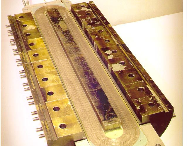
PROGRESS TOWARD THE
          VERY LARGE HADRON COLLIDER

                                     March, 2000

    “The LHC will be a great step on the energy frontier, but it will not be the last step.
Compelling questions surely lie beyond the physics reach of the LHC,” wrote the Drell
panel in 1994, adding, “The technology of the LHC does not exhaust the possibilities for
proton storage rings. Preliminary examination indicates that it may be technically feasible
to build a proton collider with beam energies up to ten times those of the LHC with
technology that could be developed during the next decade.” †
    The efforts of various researchers looking beyond the LHC came together at the 1996
Snowmass Workshop. At Snowmass, consistent parameter tables were worked out for
hadron colliders with 100 TeV center-of-mass energy and 1034 cm-2 s-1 luminosity, using
superconducting magnets in low (2 T), high (9.5 T), or very high (12.5 T) regimes. The
R&D, workshops, and other studies accomplished since Snowmass-96 support the
preliminary conclusion that a Very Large Hadron Collider of order 100 TeV in the
center-of-mass is clearly realizable with technology that is at hand, or nearly so. In most
areas it appears that the accelerator physics issues are understood, thanks to the
tremendous amount of work done for the SSC and LHC. The challenge is to make
technological advances that will significantly reduce the “expected cost” of such a
collider, where the “expected cost” is arrived at by simple extrapolation of SSC or LHC
estimates.
    In 1997 the HEPAP Subpanel report, “Planning for the Future of U.S. High-Energy
Physics” recommended “ … an expanded program of R&D on cost reduction strategies,
enabling technologies, and accelerator physics issues for a VLHC. These efforts should
be coordinated across laboratory and university groups with the aim of identifying design
concepts for an economically and technically viable facility.” ‡ The 1997 Subpanel also
called for a report on the progress of the coordination, organization and R&D in roughly
two years time. This paper is that progress report.
   In response to the Subpanel recommendation the directors of Brookhaven, Fermilab,
Berkeley Lab and Cornell University, and more recently the Stanford Linear Accelerator
Center, established a VLHC steering committee and charged it to facilitate the R&D
work at the various DOE laboratories, at universities, and in industry. The steering

†
 HEPAP Subpanel Report on a New Vision for U.S. High-Energy Physics, 1994 (Drell
Report)
‡
 HEPAP Subpanel Report on Planning for the Future of U.S. High-Energy Physics,
February 1998 (Gilman Report)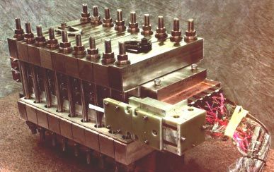
committee set up working groups in magnet technology, accelerator physics, and
accelerator technology. Each working group organized a workshop. An annual meeting
was held at Monterey, CA, June 28-30, attended by 55 interested and active participants.
The present membership of the Steering Committee and the working groups, and the
dates and locations of the workshops are listed in Table I.

                                         TABLE I.
                         A. Steering Committee Membership
William A. Barletta, LBNL; Alexander Chao, SLAC; Gerald Dugan, Cornell; Michael
Harrison, BNL; Peter Limon, FNAL; Ernest Malamud, FNAL; Stephen Peggs, BNL;
James L. Siegrist, LBNL.

                     B. Workshops and Working Group Convenors

Magnet Technology:           G. William Foster, FNAL; Ronald Scanlan, LBNL;
                             Peter Wanderer, BNL
   Workshop: Magnets for a Very Large Hadron Collider
             Port Jefferson, NY, November 16-18, 1998
             Peter Wanderer, Chair

Accelerator Technology:      Chris Leemann, TJNLF; John Marriner. FNAL;
                              Thomas Shea, BNL
   Workshop: VLHC Workshop on Accelerator Technology
             Thomas Jefferson national Laboratory Facility
             Newport News, VA February 8-11, 1999
             John Marriner, Chair

   Accelerator Physics:       Alan Jackson, LBNL; Shekhar Mishra, FNAL;
                              Michael Syphers, FNAL
   Workshop: VLHC Workshop on Accelerator Physics
             The Abbey, Fontana, WI, February 22-25, 1999
             Michael Syphers, Chair

    This document reports the activities of the VLHC working groups in the two years
since the Gilman Subpanel Report. Initial work has concentrated on magnet design, with
some effort on tunneling, accelerator physics and accelerator systems. Progress on
magnets includes development of innovative designs, some of which use new
superconducting materials. Progress in accelerator physics includes possible solutions for
transverse instability problems. Evaluations of tunneling costs and seismic effects have
begun for the Fermilab site. In the coming year, there will be continued progress in
magnet and material development, and more detailed information on Fermilab geology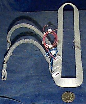
and tunneling issues. A select set of accelerator physics and technology problems will be
studied in depth at narrowly-targeted workshops.

    Although the VLHC Steering Committee is prepared to help coordinate the national
VLHC R&D effort by offering guidance to the participating institutions, such guidance
has not been necessary up to now. As the outlines of the different R&D programs show,
there is considerable cooperation among the participants and very little overlap in the
magnet designs. The steering committee has strongly supported a proposal for a national
materials R&D program in industry to improve the performance and decrease the cost of
Nb3Sn superconducting wire. The first coordinated effort in support of this effort came
out of the VLHC Magnet Technology Workshop of November, 1998, in Port Jefferson,
NY.

    A bibliography of papers and technical notes that describe in detail work referred to
in this report is attached. Many of these reports can be found at the VLHC web page,
http://vlhc.org.

Magnets
    Superconducting magnets are the most costly and technically challenging components
of a hadron collider, and they significantly constrain the design parameters of the VLHC.
Accordingly, they have been the subjects of vigorous R&D efforts. Diverse magnet
designs are being investigated. The major participants in the R&D have been Brookhaven
Lab, Fermilab, Berkeley Lab, and Texas A&M University. Coordinated work in
superconducting material R&D has been ongoing at Berkeley Lab, in industry and at a
few universities, most notably, the University of Wisconsin.

   An Overview of Candidate Magnet Technologies
   Four magnet configurations aimed specifically at a VLHC have emerged as leading
candidates for further work:

   1. The “Transmission Line” magnet: A superferric 2 T design (Fig. 1) in which a
      single superconducting cable carrying 100 kA energizes both apertures, the
      current returning by a separate conductor path. The magnet uses room-
      temperature iron and a room-temperature vacuum system. For a beam energy of
      50 TeV, the low field results in a very large ring. If the magnet and associated
      systems are inexpensive enough it may result in a collider that is least costly
      overall.
   2. A two-in-one cosine θ magnet: A “conventional” design, extending SSC and
      LHC technology to Nb3Sn (Fig. 2). This magnet is useful in its single-aperture
      configuration for many high-field applications. A cosine θ design is efficient in its
      use of steel and superconductor, and is a familiar technology used in all high-
      energy superconducting accelerators up to now.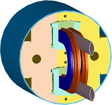
3. The “Common-Coil” magnet: A high-field design that uses simple, flat coils
(Fig. 3) to energize two gaps simultaneously. The large radius of curvature of the
windings is friendly to the use of brittle Nb3Sn and high-temperature
superconductor (HTS) and may permit small coil apertures and the use of
simplified react-before-winding techniques. Two designs, one for 10 T, another
for 15 T are being studied.
4. The “Stress Management” magnet: In this design (Fig. 4), block coils are
separated from each other by the support structure in such a way that the stress
generated in one section of the coil is not transferred to its neighbor. This
reduction in stress and advantageous block structure may allow higher magnetic
field strength.
Notable by their absence are any designs of intermediate field strength, from 2 T to 9
T. Whether such designs will be useful for a VLHC is not yet known, but it is clear that
extensive R&D in that regime is not needed at this time. Designs above 2 T to about 5 T
are already well-understood due to the extensive successful construction of magnets for
the Tevatron, HERA and RHIC. For field strengths above 5 T, we can rely on the
development for SSC and LHC. It appears that intermediate field strengths provide
neither the potential cost savings of the low-field design, nor the advantages of
synchrotron radiation damping, which significantly reduces the emittance of the beam,
offered by the high-field designs at 50 TeV beam energy. Intermediate-field magnets
could, however, offer us understood cost models for comparison studies, and might be the
appropriate choice for certain staging scenarios.
Any high-field magnets that use the familiar NbTi conductor operating in superfluid
helium cannot support the field strength that is the goal of the high-field R&D.
Furthermore, such magnets are high in cost because they use superconducting material at
the limit of its performance. Hence, Nb3Sn and Nb3Al, have been the focus of the R&D
effort. There has been some magnet R&D using high-temperature superconductor, but the
relative unavailability of high-current, compact geometry HTS cable has constrained
magnet development.
Low-Field Superferric Magnet: Design Considerations
The superferric magnet uses iron to shape the magnetic field, much as a conventional
magnet, but uses superconductor to carry the excitation current. The iron limits the
maximum field to about 2 T. There are many possible superferric designs. The one being
pursued for the VLHC is an elegant design called a “Transmission Line Magnet.” Two
apertures (Fig. 1) are arranged horizontally, with room-temperature iron carrying the flux
between them and excited by a single NbTi cable carrying 100 kA. The superconductor
and its cryostat are basically a transmission line, hence the name. The small mass of
material at cryogenic temperatures and the relatively simple construction may lead to
reduced cost per Tesla-meter.
The steel pole tips of the dipoles are shaped to produce a “combined function”
magnet (dipole and quadrupole together), eliminating the need for separate quadrupoles.
The return path for the current, and the supply and return for the helium, are contained in a
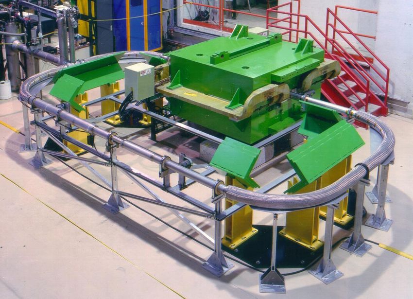
utility structure underneath the magnet. The conductor (Fig. 5) is an arrangement of
superconducting cable and Invar support pipes clamped at the magnet ends. Invar is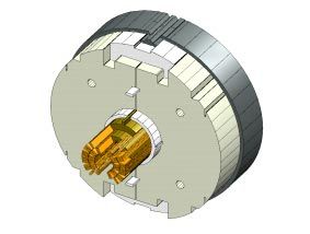
chosen because of its low temperature coefficient of expansion. The spiral arrangement
of the conductor permits it to contract independently of the Invar. The simplified design
allows the magnets to be made quite long, perhaps over 100 m, reducing the number of
magnet interconnections.
   Low-Field Superferric Magnets: R&D Progress
    In 1998, a small cryogenic test loop was built and a first one-meter model was tested.
In 1999, an extension of this test loop, 17 m in circumference, was built at Fermilab (Fig.
5) and energized to over 100 kA using a conventional magnet as the primary and the
superconducting loop as the secondary of a DC transformer. This was recently used to
test a sample of transmission line that meets all design requirements for the final
machine. The NbTi and Invar sample carried the full 100kA current at 7.1K, substantially
above the 6.5 K maximum temperature of the low-field VLHC cryogenic system design.
In the next few months, this loop will be used to test several alternative conductor
designs.
    Optimization of the 2-D iron cross section continues, using the room-temperature test
stand commissioned in 1999. The work focuses on saturation control techniques to ensure
adequate field quality up to about 2.2 T (the practical limit for field strength given a
100kA drive current). A successful proof-of-principle of the “crenelation” technique was
demonstrated last year, and a second technique based on judiciously placed holes in the
pole tips is being built. A precision 20-element Hall probe array has been delivered and
will be used for field shape measurements in the 2 cm magnet gap.
   Superconducting Materials
    Niobium-titanium, the superconductor that has been used in all superconducting
accelerator magnets up to now, will not be able to reach fields above 10 T, even in
superfluid helium. At this time Nb3Sn is the best near-term candidate for high-field
magnets. Its current-carrying capacity was significantly improved during the International
Thermonuclear Experimental Reactor R&D program (ITER), but is still below what is
desired for VLHC magnets. In the absence of other large customers, orders from high-
energy physics are essential to keep the existing technology alive and improving.
    New challenges arise when using Nb3Sn for a magnet. This material is extremely
brittle after the high-temperature reaction that forms the stochiometric compound that
becomes superconducting at liquid helium temperature. Hence, coils with small-radius
bends, such as the saddle coils of a cosine θ magnet, must be wound before the cable is
reacted. This requires electrical insulation that can withstand the high-temperature
reactions, usually glass or ceramic fibers followed by vacuum impregnation after
reaction. Coils with gentle bends, such as the “Common-Coil” design might be able to be
built from pre-reacted cable, a significant fabrication simplification. Another low-
temperature superconductor, Nb3Al, is similar to Nb3Sn but has more tolerance for strain.
Some R&D on this material is being sponsored through SBIRs.
    Most of the processes used for making Nb3Sn and Nb3Al lead to large effective
filament sizes and, hence, poor field quality at low field. This is exacerbated by magnet
designs that have large amounts of superconductor and small coil diameters. Although
some of these problems can be relieved by judicious design, such as the use of steel
shims, it will take a significant R&D investment in superconducting materials to
completely solve the magnetization issue. The “powder-in-tube” method of making
Nb3Sn conductor holds promise of yielding high current density and small effective
filament size, but the technique is relatively new and needs further development.
For accelerator magnet applications, HTS entails high technical risk but has the
potential for high reward. The materials of interest are BSCCO and YBCO. The current
density of BSCCO is presently insufficient for a high field accelerator magnet but is
increasing each year and present indications are that it will continue to increase. BSCCO
development continues to attract large investments from the private and government
sectors, including DOE funding of about $30M a year. Much of this investment is
directed toward obtaining more efficient electrical transmission lines and motors. The
results of these efforts are likely to help create better conductor for magnets, as well.
Superconducting Materials: R&D Progress
A consortium of DOE laboratories and universities has proposed an R&D program
for Nb3Sn and Nb3Al to be carried out in industry over the next five to ten years to
encourage continued improvement in performance and cost reduction. The DOE has
agreed to fund this effort at $500,000 for the first year, starting in January, 2000. A
Steering Committee comprising laboratory and university membership has written a
Request for Proposals, the responses to which will soon be evaluated.
A facility for reacting and testing superconducting strand has been set up and
commissioned at Fermilab. It is capable of operating up to 17 T, and from 1.8 K to 100
K. LBNL and Fermilab have collaborated with the National High Magnetic Field
Laboratory (NHMFL) in Tallahassee, FL, in the use of their cable-testing facility, which
has the capability of putting strain on the cable during testing, which is an important
parameter for Nb3Sn.
A few hundred kilograms of excess ITER Nb3Sn that belongs to DOE has been drawn
down to useful sizes from 0.3 mm to 1.0 mm for use in mechanical models of high-field
magnets. This material is not good enough to make high-field magnets but its mechanical
properties are typical of Nb3Sn, permitting early, accurate and inexpensive studies of the
fabrication techniques and mechanical properties of these magnets.
In the low-field R&D, Nb3Al strand has been used to manufacture four 4 m long
transmission line test sections for use in the 100 kA inductive test loop. The advantages
of Nb3Al include a higher current density than NbTi, and the cryogenic cost savings from
running at temperatures as high as 11 K, while retaining the flexibility and ductility
required for a reliable field splice.
High Field Magnets: General Considerations
At high fields, high-energy proton beams emit significant amounts of synchrotron
radiation. This is both good and bad. Radiation damping is beneficial as it reduces the
emittance (size) of the beam, thus increasing the integrated luminosity. It may also make
the beam less sensitive to the deleterious effects of field distortions, power supply and RF
noise, and ground motion. However, the radiation presents an increased heat load to the
cryogenic system and causes desorption of gas molecules from the beam tube, both of
which require a beam-tube liner, which complicates the cryogenic, vacuum andmechanical system of the magnets. Much progress in understanding the effect of
synchrotron radiation on proton collider operation has been made since the SSC first
started investigating it in 1984. Nevertheless, it remains one of the most challenging
issues of high-energy, high-field colliders.
High-field magnets necessarily have a large amount of superconductor, and Nb3Sn
has a very high critical current density and relatively large filament diameters, resulting
in large magnetization currents at injection field. Investigators have made progress in
designs that use steel shims on the beam tube or behind the coils to partially cancel the
injection field errors. At high field the steel shims are completely saturated and have no
influence. This is a promising technique that will be pursued further.
High-Field Cosine Θ Magnet Design Considerations
An effort underway at Fermilab in a collaboration with LBNL and KEK focuses on
obtaining the maximum performance from Nb3Sn in a two-layer, cosine θ coil. This
wind-and-react coil is designed to take advantage of numerous advances in materials and
tooling; it is insulated with ceramic cloth, allowing a higher temperature reaction; the
cloth has a ceramic binder that can be partially cured at moderate temperature, binding
the coil together for easy handling, but which leaves no carbon residue after coil reaction;
the tooling is designed to allow the coils to be wound, cured and reacted as a complete
unit, shortening and simplifying the fabrication.
This design combines the high-field capability of Nb3Sn with the large body of
experience building NbTi cosine θ magnets for the Tevatron, HERA, RHIC, and the
LHC. The magnet design is intended to produce an 11 T operating field with a 45 mm
coil aperture. Work has included comparisons with other designs (e.g., the common-coil),
field quality optimization of the coil straight section and ends, and calculations of the
electromechanical forces. Ovens large enough to react Nb3Sn conductor in the form of a
coil have been installed, a facility for measuring the critical currents of Nb3Sn wires has
been brought into operation, and measurements of material properties have been made.
The initial R&D models have a single aperture, but the design of a two-in-one version
was completed in December, and will be fabricated in 2001.
High-Field Cosine Θ Magnets: R&D Progress
Most of the tooling infrastructure for making shell-type magnets is in hand because of
Fermilab’s long tradition of making magnets of this kind, and because of the recent LHC
R&D program. Additional infrastructure specific to Nb3Sn magnets is in place and is
being used, including small ovens for sample preparation and a large oven for reacting
model magnets up to one meter in length. The goal of the Fermilab cos θ program is to
build and test a working single-aperture magnet in fiscal year 2000. The magnetic and
engineering design are complete and most of the tooling is in hand or has been ordered.
Oxford Superconducting Technologies, Inc. has made and delivered high-performance
strand to Fermilab for the first model. IGC Advanced Superconductors, Inc. and Shape
Metal Innovation, BV (The Netherlands) are making superconducting strand for future
models. Coil samples for the mechanical models (Fig. 6) are being wound, cured, and
reacted from spare ITER cable using ceramic insulation made by Composite Technology
Development, Inc. Two mechanical/electrical models will be made from ITER cable inFebruary and March, followed by fabrication of a magnet from high-performance cable
made at LBNL. Investigators expect tests of the first high-field model in August.
High-Field Common-Coil Magnet Design Considerations
A common-coil dipole uses flat racetrack coils, arranged to produce uniform dipole
fields in two apertures in a single magnet. (Fig. 3). Racetrack coils, in contrast to saddle
coils, bend the conductor in only one plane. Furthermore, in the common-coil design, the
radius of the bends is of the order of the aperture spacing rather than the size of the
aperture. Thus these coils are “conductor friendly” and more suitable to the brittle A15 or
HTS materials required for high field.
Brookhaven, Fermilab and LBNL are all working on one or another variant of a
common-coil magnet. Brookhaven is pursuing the design with the intention of eventually
using high-temperature superconductor for very high field and low operating cost. The
goal at LBNL is to build a very high-field dipole (B>15 T) from Nb3Sn or Nb3Al,
possibly using react-and-wind techniques. Fermilab’s plan is similar, except that the goal
is a 10 T dipole with the inner coils made of Nb3Sn, the outer of NbTi. A major choice in
the design is whether to use “auxiliary coils,” that is, coils separate from the main coils,
to enhance the field. Such designs are more difficult to fabricate but are considerably
more efficient in their use of superconductor.
High-Field Common-Coil Magnet: R&D Progress
Two 1 m-long common-coil dipoles have been successfully tested in the last year, one
at Brookhaven, one at Berkeley Lab. Both models used existing superconductor to obtain
a relatively fast check of design and construction methods at moderate field. The LBNL
magnet (Fig. 7) performed well, reaching the 6 T limit of the ITER superconductor
without training. The LBNL group is now well along in its design of a common-coil
magnet able to reach 14 T. The LBNL and Fermilab staffs are working together on the
field quality aspects of this design.
The other common-coil dipole was built at BNL using NbTi left over from the SSC,
to generate a 6 T background field in a yoke designed for easy changing of additional test
coils. The intention is to use this magnet to test HTS coils, but in the absence of available
HTS materials, test coils were made from industry-donated pre-reacted Nb3Sn tape,
which has strain characteristics similar to Nb3Sn. The quench performance of both the
NbTi and the Nb3Sn coils was satisfactory. The coil manufacturing and assembly
techniques used for the Nb3Sn coils are now being used to build coils made from pre-
reacted BSCCO HTS. The BNL staff also made a successful short (30-cm) common-coil
magnet coil using BSSCO tape. (Fig. 8)
Small purchases of BSSCO material have been made by BNL, LBNL and Cornell in
order to provide manufacturers with feedback about its use in high field magnets. In
1998, HTS coils were ordered jointly by BNL, Cornell and Fermilab from two vendors,
Intermagnetics General Corporation (IGC) and Applied Superconductivity Company
(ASC). Meanwhile, a quadrupole suitable for the Cornell Electron Storage Ring was
designed. Using a winding mandrel made at Fermilab, ASC wound two quarter-coils
(Fig. 9), which tested successfully at their facility and at BNL. Late in 1999, IGC also
completed two quarter-coils, which are currently under test at BNL.The magnetic design of the Fermilab common-coil magnet is complete, and finite
element analysis and tooling design is proceeding. Since the goal is to make a Nb3Sn
react-and-wind magnet, investigators are paying considerable attention to the cable
design. Cables with strand diameters of 0.3 mm, 0.5 mm and 0.7 mm are being made at
LBNL with and without a central stainless steel core. This core prevents the strands from
welding during reaction, and also decreases the AC losses. The cables are being reacted
at Fermilab for strain tolerance tests. Tooling is being procured, and magnet coil winding
will follow quickly on the heels of the cosine θ coils. Fermilab expects to test a magnet in
early 2001.
High-Field Stress-Management Design Considerations
In this approach (Fig. 4), the magnet is designed so that the large electromagnetic
forces produced by high fields do not accumulate in a coil and degrade the performance
of the brittle superconductor. Instead, the coil is constructed of a series of blocks of
conductor supported by a system of Inconel ribs and plates. The stainless steel structure
carries the force on each coil block to an external support structure. At the magnet end,
the coil is wound over the beam pipe in a region of relatively low field.
The subdivision of blocks makes it natural to use a “graded conductor” design in
which the costly high-field materials are only used in the coil that is closest to the beam,
with cheaper materials such as NbTi in the low field regions. Also, the Cu-to-SC ratio
can be different in the different blocks. Stress-management designs for both 16- and 12-T
magnets have been developed. Electrically, there are three independent coils in each
magnet. Field quality is maintained through the ramp by varying the currents in each coil
as needed. The design of the magnet shields the beam from the magnetization currents at
injection field, increasing the range over which the magnet can be operated. Proper
support of the coil block under all conditions requires a novel spring to make up for
changes in the relative sizes of the coil block and its support structure. It also requires a
slip plane and electrical insulation between the coil and the support structure.
Accelerator Physics
The major work in the area of accelerator physics has focused on aperture and its
relationship to both single-particle dynamic aperture, particularly at injection, and
collective effects. This is appropriate at this stage of the VLHC studies because magnet
cost is strongly dependent on physical aperture. Other important issues have been
discussed at workshops, and have been left to future studies and experiments. These will
be discussed in the section on future work.
Single-Particle Effects—Dynamic Aperture
The design and development of the SSC and the LHC significantly advanced the
understanding of the dependence of beam lifetime and emittance growth on magnet field
quality, correction systems and cell length, and the dependence of field quality on magnet
physical aperture. They need to be revisited for the VLHC because technological and
theoretical advances and anticipated design changes, such as the use of Nb3Sn magnets,and the influence of synchrotron radiation damping, have changed some of the
underlying assumptions.
Magnet field quality and aperture
For superconducting magnets, decreasing the inner coil radius can lower the cost. On the
other hand, single-particle stability and collective effects suggest that the coil radius and
the beam pipe radius be as large as possible. The choice of optimal single-particle
aperture depends on injection energy, injection errors, orbit distortions, lattice
mismatches, power-supply ripple, correction schemes and half-cell length in the arcs. It is
important in setting the aperture of the magnets that we understand the expected
distribution of systematic and random field errors in the arc magnets.
For conductor-dominated (high-field) magnets, single-particle considerations at
injection usually set the lower bound on coil aperture, where magnetization effects and
large beam size conspire to make the effects most damaging. For superferric magnets, the
field quality at injection is not likely to be a concern since the field is shaped by iron pole
tips and the magnet is insensitive to persistent currents in the superconductor. The field-
quality challenges for the low field magnet occur at peak field, when the iron enters
saturation. At peak field, however, the dynamic aperture requirements have dropped by a
large factor due to the adiabatic damping of the beam size. Thus the minimum workable
aperture of superferric magnets will likely be set by other considerations
During the design of the SSC magnets it was expected that random errors would be
larger than systematic errors. Experience with RHIC dipoles, as well as with the last SSC
dipoles built, has shown that random errors were much smaller than expected. Some of
this overestimate may have been due to simplifications of the initial mechanical model,
but most of the improvement was achieved by better tooling, better control of
manufacturing processes, and reduction of measurement errors. Systematic errors have
also been reduced by improvements in the design of NbTi magnets, but magnets with
Nb3Sn coils will probably have much worse magnetization effects at injection. Some of
this can be moderated by the judicious use of steel shims and by aggressive R&D to
reduce conductor filament diameter. Even with good results in those areas a complete set
of correctors and the right choice for cell length and injection energy will be necessary to
optimize the injection aperture and the cost of the collider.
Optimum cell length
One of the key cost drivers is the cell length. Longer cell length implies fewer
quadrupoles, sextupoles and other correctors, but it also increases the beam size and
makes the beam more sensitive to field errors. How the transverse and longitudinal beam
parameters scale with cell length depends on the distribution of field errors and how they
affect the dynamic aperture. Where the dynamic aperture is dominated by chromaticity
correction sextupoles, longer cell lengths are favored, as this reduces the required
sextupole strengths. In other circumstances—either when systematic errors are large or
when random errors are dominant—shorter cell lengths would lead to a larger dynamic
aperture.Collective Effects
The strongest instabilities expected in the VLHC are the single-bunch transverse
mode coupling instability (TMCI—sometimes called the “fast head-tail instability”), and
a low frequency transverse multi-bunch instability. Both effects are most severe at
injection energy. The multi-bunch instability is driven primarily by the resistive wall
impedance; the TMCI instability is driven primarily by the resistive wall impedance in
the low field case, and by the broadband impedance in the high field case. Thus, the low-
field design, with its much larger circumference and room-temperature vacuum chamber,
has the lowest threshold for the single bunch TMCI and the most rapid growth rates for
the multi-bunch instability.
Transverse Mode Coupling Instability (TMCI)
The frequencies of coherent bunch motion (mode 0) and head-tail motion (mode -1)
are shifted towards each other by the transverse impedance. At some threshold current,
the mode frequencies become equal, and the bunch becomes unstable, with a very rapid
growth time (on the order of the synchrotron period). As noted above, this is particularly
an issue for the low-field design because of its large impedance. The situation is clouded
by the fact that this instability has only been observed in electron machines (which have
much shorter bunch lengths) and has never been seen in proton machines. Nonetheless, if
the instability formulae are valid and if no further measures are taken, this instability has
the potential for limiting the achievable luminosity.
Calculations up to now indicate that the TMCI does not limit the luminosity below
1034 cm-2s-1, but this is still controversial. Several methods of raising the beam-current
limit due to the TMCI in the low-field design have been proposed to avoid the
straightforward but costly solutions of raising the injection energy or increasing the beam
tube diameter. These include rf quadrupoles or coalescing beam at higher energy than
injection to reduce bunch intensity at low energy. Some of the proposed methods are
unproven, requiring further R&D. Of the various schemes, conventional feedback
systems have been shown to increase the instability threshold in the electron machines
PEP and VEPP-4M and may work in the VLHC, although that is controversial at this
time. Nevertheless it is worth studying the different schemes in some detail to see which
leads to the lowest-cost solution and increases the instability threshold.
Transverse multi-bunch instability
The multi-bunch instability is most severe at injection energy; the growth time is
proportional to the total beam current. It is driven by the low-frequency transverse
impedance resulting from the finite conductivity of the beam pipe walls. At 3 TeV, the
instability growth time in the low-field VLHC varies from 0.4 to 4 turns (depending on
lattice parameters), and is about 300 turns in the high-field case. The instability can be
damped with use of a distributed feedback system. This system senses the beam position
error and generates an amplified kick 90 degrees in phase advance from the pickup. Of
course, the kick is slightly out of phase with the error, due to electronic propagation
delays, but the correction works anyway due to the slow nature of the change in position
error. Spacing a number of such systems around the ring will decrease the damping time
considerably. It is estimated that ten such feedback systems in the ring would besufficient to create a damping time of less than a third of a turn and eliminate this as a
luminosity-limiting effect. This needs to be confirmed by detailed simulations.
Beam Loss and Energy Deposition
Stored energy in the beams is very high in the VLHC: about one gigajoule for the
high-field option and about 10 GJ for the low-field case, compared to 0.33 GJ in the
LHC. Measures must be taken to protect people, the environment, and the accelerator
from the consequences of beam loss. This is not a fundamental accelerator physics issue,
but it will require care to cope with both operational beam loss and accidental beam loss.
Operational loss refers to the relatively slow and steady loss resulting from halo
particles interacting with limiting apertures. It results in reduced luminosity lifetime,
potential vacuum problems, activation of components and other unpleasant
consequences. There exists a preliminary design of a two-stage collimation system to
deal with operational beam loss similar to one used at HERA and an LHC design.
Accidental losses might occur, for example, due to the misfire of one of the abort
kickers, resulting in a large amount of beam hitting part of the collider. The high stored
beam energy could destroy a magnet or a detector. A system of three appropriately placed
absorbers has been designed for the LHC to protect interaction-ring magnets from
unacceptably large increases in temperature as a result of these kicker misfires. A similar
design should also work for the VLHC, but alternative ideas could be more cost effective
over the long run.
Accelerator Technology
Civil Engineering
The construction of the collider enclosure is an important cost driver for the VLHC,
especially for the low-field version. Therefore, investigators are studying the
development of new tunneling technologies. Two important advantages to building the
VLHC at Fermilab are the existence of the injector chain and the excellent geology. At a
depth of 150 m, below the nearly flat Illinois surface lies a 50 m thick dolomite layer.
This relatively homogenous rock mass is ideal for siting the VLHC and its injector. It is
seismically stable and vibration free, with a very low rate of infiltration of groundwater.
The two main components in the tunnel construction are mining and muck removal.
The standard approach is to use tunnel-boring machines (TBM) for mining and a
conveyor belt for muck removal. The Kenny Construction Company has made a study of
a 34 km tunnel in the dolomite near Fermilab and has shown that a major cost driver is
the number of people underground. The mining industry is exploring new ideas and is
moving in the direction of more automation in tunnel construction.
Cryogenics
The cryogenic issues for every superconducting accelerator are threefold: operating
temperature, temperature gradients, and temperature stability. Since all of the high-field
magnets use Nb3Sn at the present time, in which Jc does not have much temperature
dependence below 4 K, the high-field magnets all operate at about 4.2 K. Therefore, thecryogenic systems for these magnets will closely resemble those of the SSC. One
significant difference comes from the increased synchrotron radiation power (several
watts per meter) deposited in the cryogenic beam screen. It is desirable to intercept this at
the highest possible temperature consistent with obtaining adequate beam vacuum and
RF impedance. This will require significant R&D in the coming years.
Of particular note is a cryogenic design for the low-field case that uses the fact that
the superconductor in the superferric magnet is in a low-field region, permitting the
coolant temperature to rise to the critical point or even higher. This may permit the use of
a cryogenic system that effectively uses the sensible heat of the cryogen, thereby
eliminating heat exchangers in the magnet system and greatly simplifying the controls.
Vacuum
The vacuum system of the low-field machine is not cryogenic, and is expected to
have a gas load from photo-desorption and outgassing similar to or less than LEP.
Although it will not be trivial, there is a demonstration that such a system will work. The
high-field machines all have beam tubes at cryogenic temperatures. Although no existing
collider actually has a beam-tube liner, all high-energy high-field collider designs (SSC,
LHC, VLHC) include a beam-tube liner inserted between the beam and beam-tube. This
liner operates at a higher temperature than the magnets, from 20 K to 80 K, and has holes
punched in it to allow desorbed gas (mostly hydrogen) to escape and stick to the beam-
tube wall. The higher-temperature liner reduces the cryogenic load, but the temperature
of the beam tube of VLHC (4.2 K), is not low enough to reduce the residual hydrogen
vapor pressure to acceptable levels. It is believed that this can be dealt with by coating
the wall with some form of adsorbant material to increase its effective surface area. This
problem has been studied at light sources in the U.S., France, and most recently and
extensively at Novosibirsk, Russia. This issue, which was one of the most troublesome
during the design phases of the SSC and the LHC, is still a thorn. Studies must continue.
Ground Motion
Ground motion can vibrate magnets, leading to emittance growth if the resulting
coherent motion is not corrected over its decoherence time. Measured ground vibrations
in deep Illinois dolomite tunnels are smaller than the tolerances for both the low- and the
high-field options. The “cultural” noise level (i.e., arising from human activities such as
nearby traffic) measured in the shallow Tevatron tunnel is several times above the VLHC
tolerances but small enough to be suppressed by the multi-bunch damper system
discussed above.
Plans for the Coming Year
Magnets
As in the past, most of the R&D effort for the VLHC nationwide will be devoted to
magnet development. Our extensive experience with existing or soon-to-be-existing
superconducting colliders indicates that eight to twelve years is a realistic estimate of the
time it will take to develop cost-effective and proven magnets for the VLHC. The present
level of effort produces no more than one short model magnet per year at each of the
laboratories. It will soon become necessary to make several short magnets per year tooptimize fundamental design features, to permit a systematic and scientific approach to
the R&D, and to allow each program to take some technical risks in its pursuit of the best
design. Thus, we envision that the budget will continue to have modest growth in the
coming three to five years. At a later stage, full-scale magnets will have to be built and
tested. This will require greater growth, and selection among the various designs to
concentrate our resources.
Each of the participating DOE Laboratories has a detailed plan for R&D that projects
one or two years. The goals of the individual laboratories’ programs and their approach to
the development challenges have surprisingly little overlap at this time. For example,
even though three laboratories are interested in developing the two-in-one common-coil
concept, the actual goals of each of the programs are so different that the resulting
designs have very little resemblance to each other. It is because of the promise of a less
costly VLHC that this particular concept has attracted so much attention.
In broad outline, the goals for 2000 are:
1. BNL—high-field, common-coil magnet: The first HTS coils designed for the
common-coil magnet will be tested using NbTi coils to provide a 6 T background
field. Since this will be the first time HTS coils are operated in this environment,
many basic measurements will have to be made to characterize their performance.
In addition, work will start on a second-generation HTS common-coil magnet,
which will be designed to operate at 12 T, and which will be used to investigate
issues such as field quality, magnetization, eddy currents.
2. Fermilab—superferric, transmission line magnet: Make and test a magnet on
the room-temperature facility using the second-generation cross section; make a
10 m magnet and test it using the induction loop at the transmission line test
facility; increase the capability of the induction loop to electrically and
cryogenically operate longer magnets; start the engineering design of a 50 m
magnet; make and test various support and superinsulation designs for the
transmission line; start to design tooling for welding, splicing, and other
installation operations; finish the design of 100 kA power leads.
3. Fermilab—high-field cosine θ magnet: Fabricate, possibly test, and dissect one
or two mechanical models; build and test the first one-meter, 11 T model using
high-performance superconductor; start to build the second model; order
superconductor for two more models to be built and tested in 2001. Start the
engineering and tooling designs for the first two-in-one models.
4. Fermilab—high-field common-coil magnet: Continue the investigation of strain
tolerance of various cables for react-and-wind technique, using spare ITER
conductor, and select a strand and cable design; complete the tooling design and
order tooling for delivery in mid-2000; react the selected ITER cable and make
and test practice coils using real tooling; assemble and test a mechanical model
using ITER cable; order high-performance strand for the first high-field (10 T)
magnet to be made in 2001.
5. LBNL—high-field common-coil magnet: Continue the current program based
on a high-field, Nb3Sn, common-coil design, paying particular attention tofabrication issues related to brittle conductor, especially cost-related issues. The
fabrication of this second-generation magnet has already begun. It is designed to
reach 14 T, limited by the performance of available superconductor. The outer
coils will be tested in the spring in a background field. The inner coils will be
assembled with the outer coils and tested in the fall.
Accelerator Physics
Fundamental limitations to ultimate hadron collider luminosity, such as the beam-
beam effect, intra-beam scattering, collective effects and instabilities, and synchrotron
radiation, will continue to be important in the VLHC parameter regime. In addition, the
magnet R&D program continues to need feedback from accelerator physics about
important issues such as field quality, aperture, and time-dependent effects.
Emittance damping from synchrotron radiation enhances the equilibrium beam
density by an order of magnitude compared to the nominal injection value. The dynamic
evolution to denser beams leads to stronger and more complex beam-beam interactions.
Although the damping times are long compared to those in electron machines, an
additional potential increase in luminosity comes from the flat beams that ensue if the
linear coupling terms are small enough. Since interaction region optics designs are
strongly influenced by the beam size and shape, it is important to understand this new
beam dynamics regime.
The VLHC will confront some or all of these fundamental physics limitations to its
ultimate luminosity, many of which are amenable to beam studies and experiments that
can be performed at the Tevatron and RHIC, and eventually at LHC. Such experiments,
that are actively being pursued, will be of benefit to all hadron colliders. In these efforts,
the VLHC Steering Committee can be useful in supplying a natural venue for organizing
and coordinating mini-workshops on topics of mutual interest within the hadron collider
accelerator physics community.
Three different accelerator physics mini-workshops are planned for the coming year,
on the topics of collective effect limitations on bore size, synchrotron radiation and flat
beams, and beam dynamics experiments.
Accelerator Technologies
Civil Engineering
Investigators are pursuing a number of avenues aimed at lowering the cost per meter
of collider tunnel. Greater automation of the tunneling machines will reduce the labor
component as well as increase the advance rate. A 17-ft TBM in operation on a 4000-ft
tunnel under Chicago (part of TARP) has been instrumented by Fermilab to understand
more quantitatively the factors governing the efficiency of TBM utilization. These data
are being collected in real time and being analyzed. In addition, the possibility is being
considered to write contracts with industry to study innovative concepts in tunneling and
muck removal.
A major effort in the coming year will be to understand more exactly the geology in
the Fermilab area. This work has already been started at Fermilab, with the formation of aSiting Study Group that is concerned with all siting aspects of possible new machines
located at or near Fermilab. A first step will be connecting with the Illinois Geologic
Survey to get detailed maps of the underground and surface conditions that will be
encountered by tunneling in northern Illinois. It might be necessary to make additional
surveys. A mini-workshop on the subject will be held in the next twelve months.
Seismic measurements to date cover three ranges: 2 x 10⁻³ to 1 Hz, important for
alignment; 1 - 100 Hz, important for orbit stability; and above 100 Hz, important for
emittance growth. Measurements are being extended this year to lower frequency, near
10-7 Hz, to understand if dynamic alignment will be necessary.
Workshops
Because of the amount of R&D, we will again have a rather large magnet workshop,
this year scheduled to be near Fermilab in the spring. Instead of two large workshops in
accelerator physics and accelerator technologies, we plan to organize a larger number of
smaller, more focused workshops on specific subjects, trying to bring together the most
interested and expert scientists in each area. Examples might be beam stability and
feedback; ground motion; simulation of dynamic aperture; and perhaps some focused
magnet workshops, as well, such as cancellation of magnetization effects with steel
shims.
Mini-Workshop on Beam Dynamics Experiments Feb., 2000 BNL
Workshop on Superconducting Accelerator Magnets May, 2000 Fermilab
Mini-Workshop on Limitation Due to Collective Effects
Mini-Workshop on Synchrotron Radiation Damping
Mini-Workshop on Fermilab Regional Geology
VLHC Annual Meeting Sept., 2000 BNL
Acknowledgements
This summary represents work done by many people from national laboratories and
universities. Their work and that of the Steering Committee has been supported
principally by the Office of High Energy Physics in the Office of Science at the U.S.
Department of Energy under contracts with these institutions.20 cm.
2-in-1 Warm-Iron
“Double-C” Magnet
Flux Return
Extruded Aluminum
Beam Pipes with side
pumping chamber
LHe
100 kA Superconducting
Transmission Line Alternating-Gradient
Í
Pole Tips (no Quadrupoles)
structure is continuous
in long lengths
Helium
Return Structural Support Tube/
Line CryoLineVacuum Jacket
Cryopipes for Ring-
Wide Distribution of
Single-Phase Helium
Supply
Line
Current Return
Figure 1. A cross-section of a “transmission-line” magnet. Current Figure 2. A single-aperture version of a “cosine θ” design.
flowing down the central conductor excites a magnetic field in the The Roman arch coil configuration results in mechanical
surrounding iron and the two gaps. The maximum field attainable is stability without internal support, and is similar to all high-
approximately two Tesla. The simplicity of the design may result in low- energy collider superconducting magnets used until now.
cost magnets and accelerator systems. This design is for R&D. The collider magnet will have a
double aperture, and can sustain fields up to about 13 T.400 mm
50 mm
30 mm
Figure 3. The “Common-coil” magnet has simple, flat coils with Figure 4. A concept for a “stress-management” magnet, in which the
gentle radii of curvature friendly to brittle conductors such as pre- outward forces from the inner coils are transferred directly to the yoke
reacted Nb3Sn and high-temperature superconductor. The coils without acting through the other coils, reducing stress on the
require internal support for mechanical stability, but their superconductor. Block configurations of this type may be necessary to
simplicity suggests a less-costly high-field magnet. Attainable field attain very high magnetic fields, greater than 15 T.Figure 5. The Fermilab Transmission-Line Test Facility. The conventional magnet is configured as a DC transformer; the secondary is a superconducting loop. This facility has been energized to over 100 kA, and has a four meter long replaceable section used to test various conductor and splice configurations.
Figure 6. Coils for a mechanical model of the cosine θ magnet. The Nb3Sn cable is insulated in ceramic cloth (left) sized with a material that
binds the coil when cured at moderate temperature (right), but which leaves no carbon residue when reacted. This greatly simplifies assembly.
Figure 7. Apparatus used at BNL for testing HTS coils in a common-coil configuration and in a background field. The background field is
supplied by outer NbTi coils (right), and the inner coils are various HTS coils (left). This easily modifiable setup allows fast turn-around in
testing different materials and geometries at high field.
Figure 8. The first example of the LBNL common-coil magnet. This            Figure 9. These HTS coils from IGC Advanced Superconductors, Inc. are
magnet was easily and quickly assembled, and attained its moderate short-   two of four made in industry for Cornell University to verify the concept
sample limit without training. The field strength was limited by the poor   of a moderate-gradient quadrupole that can operate at 30 K and which
quality of the available conductor, but the ease of assembly suggest        takes little space. Two other coils have been successfully made by the
possible cost-reduction capability of this concept.                         American Superconductor Corporation.
You can also read