VGS FACILITY INSTALLATION STANDARDS - March 2021, Rev. 0 - Vermont Gas
←
→
Page content transcription
If your browser does not render page correctly, please read the page content below
VGS FACILITY INSTALLATION
       STANDARDS
       March 2021, Rev. 0
PAGE INTENTIONALLY LEFT BLANK
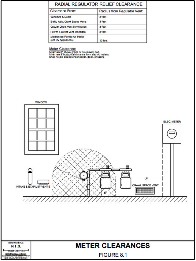
TABLE OF CONTENTS
Table of Contents
 REVISION LOG .................................................................................................................................... iii
 SECTION 1: Introduction..................................................................................................................... 1
    1.1 Purpose ......................................................................................................................................... 1
    1.2 Service Territory .......................................................................................................................... 1
    1.3 Contact Information ..................................................................................................................... 1
    1.4 Abbreviations ............................................................................................................................... 2
    1.5 Definitions .................................................................................................................................... 2
 Section 2: Pipeline Facilities Overview & VGS Programs ................................................................. 5
    2.1 Overview ...................................................................................................................................... 5
    2.2 VGS Programs.............................................................................................................................. 5
 SECTION 3: DigSafe® & Cross Bores ................................................................................................ 7
    3.1 DigSafe® ...................................................................................................................................... 7
    3.2 Cross Bores .................................................................................................................................. 7
 SECTION 4: Legislation & Governing Codes ..................................................................................... 9
    4.1 Federal .......................................................................................................................................... 9
    4.2 State .............................................................................................................................................. 9
    4.3 City & County .............................................................................................................................. 9
 SECTION 5: Right-of-Way Agreements, Land Use & Encroachments .......................................... 10
    5.1 Right-of-Way Agreements ......................................................................................................... 10
    5.2 Land Use Information ................................................................................................................ 10
    5.3 Encroachments ........................................................................................................................... 11
 SECTION 6: General Requirements for Developers, Contractors & Builders: ............................. 13
    6.1 General Application and Scheduling Requirements .................................................................. 13
    6.2 Site Plans and Site Preparation................................................................................................... 13
 SECTION 7: Gas Mains & Service Lines .......................................................................................... 16
    7.1 Gas Mains................................................................................................................................... 16
    7.2 Gas Service Lines ....................................................................................................................... 16
 SECTION 8: Regulators, Meters, Piping & Barricades ................................................................... 19
    8.1 Regulators: ................................................................................................................................. 19
    8.2 Meters:........................................................................................................................................ 20
    8.3 Piping ......................................................................................................................................... 20
    8.4 Barricades/Barriers:.................................................................................................................... 33
    8.5 Gas Meter Recess ....................................................................................................................... 35

                                                                             i
TABLE OF CONTENTS
8.6 Gas Meter Enclosures................................................................................................................. 37
SECTION 9: Working in the Vicinity of Gas Lines .......................................................................... 39
9.1 Damages to VGS piping system: ............................................................................................... 39
Section 10: Infill Services & Natural Gas Service Line Installation ................................................ 41
10.1 Infill Services.......................................................................................................................... 41
10.2 Natural Gas Service Line Installation..................................................................................... 41
Section 11: Fuel Lines, Pool Heaters & Underground Piping .......................................................... 43
11.1 Getting Started ........................................................................................................................ 43
11.2 Next Steps - Customer and contractor will be responsible for the following: ....................... 43
11.3 Final Steps .............................................................................................................................. 44
Section 12: Natural Gas Service to Mobile Homes and Mobile Home Parks.................................. 45
12.1 Feasibility ............................................................................................................................... 45
12.2 Natural Gas Distribution Main ............................................................................................... 45
12.3 Natural Gas Service Lines ...................................................................................................... 45
12.4 Conversion of Appliances ...................................................................................................... 46
Section 13: Customer Dig Guidelines ................................................................................................. 48
13.1 Permits .................................................................................................................................... 48
13.2 Easements ............................................................................................................................... 48
13.3 Digging within a Public Right of Way ................................................................................... 48
13.4 Dig Safe .................................................................................................................................. 49
13.5 Scheduling of Construction .................................................................................................... 49
13.6 Construction............................................................................................................................ 49
Page iiREVISION LOG
This plan will be reviewed and updated at least once each calendar year.
Revision Date Approver Changes
March 11, 2021 John St.Hilaire Added Exactix online ticket system link for Dig-Safe.
Updated definitions. Updated Energy Efficiency Programs
statement. Added functioning links to Section 4. Updated
section 8.1a to include meters. Updated 8.4a, removing
requirement to paint barricades yellow, and added general rule
to install barricades 4-feet from building exteriors, with 12-
inch clearance. In 13.3, removed “Menard & Sons” and
“Champlain Construction” from qualified excavation
contractor table.
May 18, 2020 John St.Hilaire Updated meter drawings to include measurements from
base of meter to outlet piping. Updated Section 13,
Customer Dig Guidelines to include trench length to be
available for inspection, deposit required when digging in
a public right of way and fees or rescheduling if VGS
downtime due to customer dig. Added distance between
exterior of building and barricades.
May 15, 2019 John St. Hilaire Added information related to PE review of all new gas
facilities up to outlet of meter.
Updated drawings 7.1, 8.2, 8.4 and 8.8.
June 1, 2018 7M Rotary meter manifold (Regulators, Meters, Piping &
Barricades)
March 23, 2018 Elevated pressure piping must be welded; requirements
for 2M/3M/5M rotary meters, and barricade painting
requirements (Meters, Regulators & Piping)
March 31, 2017 Administrative changes
Sept. 26, 2016 Gas meter recess and enclosures (Regulators, Meters,
Piping & Barricades.)
Gas meter on post with Flex-house (Natural Gas Service
to Mobile Homes & Mobile Home Parks)
Disclaimer for manual changes: Only significant changes and amendments have been
documented. Changes related to grammar or those which do not substantially modify response
operations are not documented.
Page iiiPAGE INTENTIONALLY LEFT BLANK
INTRODUCTION

SECTION 1: Introduction
1.1     Purpose
This handbook outlines the standards and procedures to be followed when working near or around
VGS(Vermont Gas Systems, Inc.) facilities or when requesting the installation of natural gas
facilities. The handbook is intended for use by city/state planners, engineers, land surveyors,
landowners, customers, developers, builders, and other private contractors. When installing new
natural gas facilities or working in the vicinity of facilities, project delays can be avoided, and safe
practices can be attained if VGS is included in the initial planning stages.
The handbook is designed to make you aware of the most common standards and procedures VGS
typically requires to install and protect its facilities. This handbook is intended to be a guideline
and is not a complete set of rules governing natural gas installations. Each proposed development,
project, or activity, however, may require a case specific evaluation by a qualified VGS
representative.
VGS feels that compliance with this manual will ensure a quality installation in a timely manner.
If you have further questions or need assistance, please contact the VGS office at (802) 863-4511
or toll free at 1-800-639-2112.

1.2     Service Territory
Maps showing our service territory are available at: https://vermontgas.com/help-center/coverage-
map/.

1.3     Contact Information
Gas Leaks and/or Odor Complaints:              1-800-639-8081 (DO NOT USE E-MAIL)
General Questions, Phone:                      1-800-639-2112
General Questions, E-mail:                     customerservice@vermontgas.com
Energy Efficiency, E-mail:                     efficiency@vermontgas.com
Company Web Address:                           www.vgsvt.com
Office Address:                                85 Swift Street
South Burlington, Vermont 05403
Dig-Safe® (“CALL BEFORE YOU DIG”):                       811
Dig-Safe® Web Address:         www.digsafe.com
To request a ticket online, visit https://exactix.digsafe.com/login. For answers to your questions
about installations call:

      New Line Requests:                                                   (802) 863-4511 ext. 336
      Customer Service:                                                    (802) 863-4511 ext. 250

                                                Page 1
INTRODUCTION
Right-of-Way, Easements: (802) 863-4511 ext. 368
Construction (sleeve designs, meter location, gas pipeline (802) 863-4511 ext. 335
design, customer dig, installations, scheduling):
1.4 Abbreviations
AGA American Gas Association
API American Petroleum Institute
ANSI American National Standards Institute
ASME American Society of Professional Engineers
ASTM American Society for Testing and Materials
BTU British Thermal Unit
BTUH British Thermal Unit per Hour
CCF Hundred Cubic Feet
CF Cubic Foot
CFH Cubic Foot per Hour
DOT Department of Transportation
EFV Excess Flow Valve
HDD Horizontal Directional Drill
IPS Inches per second
MBTUH Thousand British Thermal Unit per Hour
MCF Thousand Cubic Foot
MCFH Thousand Cubic Foot per Hour
MMBTUH One Million British Thermal Unit per Hour
OQ Operator Qualification
PHMSA Pipeline & Hazardous Materials Safety Administration
PSIG Pressure in Pounds per Square Inch Gauge
ROW Right-of-Way
WC Pressure in Inches of Water Column
1.5 De�initions
Appliance: Any device that utilizes natural gas as a fuel or raw material to produce light, heat,
power, steam, refrigeration or air conditioning.
British Thermal Unit (BTU): The quantity of heat required to raise the temperature of one pound
of water one degree Fahrenheit.
Building: Shall mean a structure that stands alone or is cut off from adjoining structures by
firewalls, as defined by the municipality or the authority having jurisdiction, with no openings or
penetrations and doorways to be protected by approved fire doors.
Casing: Steel conduit used to protect steel transmission lines and steel or plastic distribution mains
in certain situations. Casing requirements will be based on API recommended practice RP-1102
and the design must be approved by the VGS Engineering Department.
Page 2INTRODUCTION
Combustible Material: Any material such as wood, paper, sheet rock, fibers or other materials
that will smolder, ignite or burn when adjacent to or in contact with heat producing appliances,
vent connectors, gas vents, chimneys, or hot water pipes.
Combustion Air: Air supplied to an appliance specifically for the combustion of fuel.
Cubic Foot of Gas: The amount of gas that occupies one cubic foot of space when at a temperature
of 60 degrees Fahrenheit, and under pressure equivalent to that of 29.92 inches of mercury.
Curb Valve: A shut-off valve in a gas service line, usually located between the curb and a
customer’s property.
Customer Dig: Upon VGS approval, the customer may be permitted, at their expense, to trench
and backfill within the exact specifications provided by VGS.
Customer Owned Piping: The piping that is installed after the company’s meter set that connects
the customer’s appliances and equipment to the gas supply. Customer Owned Fuel lines are the
responsibility of the customer.
Department of Transportation (DOT): The federal regulatory agency that governs gas pipeline
safety, transportation of hazardous materials, and administers regulations related to highway
rights-of-way.
Developer: Person or company that invests in and develops real estate, especially by subdividing
the land into home sites and building houses. In this document this also includes site contractors
and builders.
Dig-in: Damage caused to VGS pipelines and/or facilities by digging into them during excavation
activities, either by hand or mechanized equipment.
Easement: A document conveying legal interest to use land, from its owner to another party, for
a specified purpose. Easements provide VGS the legal right to access property, install, maintain,
replace, and abandon natural gas pipelines or facilities on privately owned lands that are outside
the public Right-of-Way.
Excess Flow Valve: An excess flow valve (sometimes called an EFV) is a device that is installed
in a natural gas piping system that restricts gas released in the event the pipe is severed downstream
of the EFV.
Gas Main or Distribution Main: The piping system owned by the company that is used for the
distribution of gas that is (a) located within the limits of any public highway or on a private right
of way or (b) is used to supply gas to two or more gas services.
Greenbelt: That area of a public street located between the roadway edge and the sidewalk, or, if
no sidewalk exists, between the roadway edge and the adjacent property line.
Infill Service: A service that is installed off a preexisting distribution main.
Input Rating: The gas burning capacity of an appliance in BTU/Hr. as specified by the
manufacturer.
Page 3INTRODUCTION
Loads-Connected: The sum of the rated BTU/Hr. input of all connected gas equipment. May also
be expressed in cubic feet per hour.
Locator Wire: A wire installed with all plastic pipe (including mains and services) to ensure being
able to readily locate the buried piping in the future.
Make Up Air: The volume of air, either outside or inside, that is supplied to a space to replace air
consumed by the gas burning appliances, exhausted or otherwise removed from the space.
Mechanical Exhaust Appliance: An appliance with a venting system designed to remove flue or
vent gases by mechanical means utilizing induced draft under non positive pressure or forced draft
under positive pressure.
Meter: An instrument installed by the company to measure the volume of Natural Gas delivered
to a customer.
Pipe: Any pipe or tubing used in the transportation of gas.
Primary Air: The combustion air that mixes with the gas before it reaches the burner.
Qualified Installer: An individual who is qualified by the company or an authority acceptable to
the company.
Regulator: Control valve in a pipe system that reduces and maintains a required gas pressure.
Right-of-Way (ROW): An agreement by which a property owner grants permission to another
party to use a portion of his or her land for a specific purpose.
Secondary Air: The air externally supplied to the flame at the point of combustion.
Service Line: A part of the pipeline distribution system that transports gas from the street main to
the individual customer.
Service Riser: A vertical pipe, adjacent to a customer’s facility that runs from the service line to
the customer’s meter.
Sleeve: Non-metallic conduit that may be installed prior to installation of gas pipe at road or ROW
crossings. Sleeves are not load bearing, have no pressure and shall only be used to insert gas
carrier pipe and/or locator wire.
Valve Box: A vertical tube that is capped at ground level and usually located near the street. Its
purpose is to protect the access point to the underground shut-off valves.
Page 4PIPELINE FACILITIES OVERVIEW & VERMONT GAS PROGRAMS
Section 2: Pipeline Facilities Overview & VGS Programs
2.1 Overview
VGS delivers clean, affordable natural gas to over 54,000 families and businesses in Chittenden,
Franklin and Addison counties. VGS owns and operates over 118 miles of transmission pipeline
with over 70 million cubic feet per day at peak capacity. The transmission line currently extends
from the Canadian Border in Highgate, VT to Middlebury, VT. The transmission operation
includes high-pressure steel pipeline ranging in diameter from two (2-inch) to sixteen (16-inch)
inches, meter and regulating stations or gate stations, odorization equipment, mainline valves,
cathodic protection equipment, and other related facilities. Gate stations reduce the pressure in the
transmission line and feed into the distribution main network.
VGS owns and operates over 864 miles of distribution main which consists of both high-density
polyethylene plastic (PE) pipe and cathodically protected steel ranging in diameter from 3⁄4-inch
to 10-inch. VGS services are both high density polyethylene plastic (PE) pipe and cathodically
protected steel and range in diameter from 1⁄2-inch to four (4-inch) inches. A service to a
residential home typically is 1⁄2-inch or 3⁄4-inch PE.
VGS does not just deliver gas. We are focused on innovative solutions to help our customers save
money and reduce their energy consumption. Our award-winning efficiency programs reduce
energy use and emissions and save our customers $14 million per year – that’s real money that can
be invested in jobs, education, health care, families and communities. We also offer a first-in-the-
nation renewable natural gas adder program that gives our customers another opportunity to further
make a difference.
Our dedicated team of over 130 Vermonters is committed to our customers, our communities, our
culture and our climate.
2.2 VGS Programs
Service Department
Should customers need service of their natural gas appliances, VGS has the tools needed to offer
customers peace of mind. Our highly qualified service team is ready to help in a pinch. We also
offer a 24/7 service plan for residential heating and hot water equipment. Most parts and labor are
covered under the plan. Our service technicians are on-call, any time, day or season. Just contact
us and we will dispatch one of our professional, certified technicians to fix the problem. The 24/7
Service Plan makes good financial sense. Appliance breakdowns can be expensive and
inconvenient. The service plan covers you for just a few dollars a month.
Energy Efficiency Programs
VGS is committed to a decarbonized energy future and energy efficiency is a key component to
helping the State achieve its energy goals. Our award-winning “Energy Efficiency” programs have
been available to both residential and commercial customers since 1992 and VGS was officially
designated an Energy Efficiency Utility (“EEU”) by the Public Utility Commission in 2016.
Page 5PIPELINE FACILITIES OVERVIEW & VERMONT GAS PROGRAMS
VGS has an expert energy efficiency team that offers residential and commercial rebates and
technical assistance. To help our customers invest in the installation of cost-effective high
efficiency equipment, insulation, and air sealing measures we also offer zero to low interest
financing in partnership with Green Mountain Credit Union
VGS is committed to serving all customers through its energy efficiency programs. All of
programs support cost effective projects and improve a home or building’s performance. The
benefits of saving energy are typically complemented by an increase in comfort levels, lower
carbon emissions, improved productivity, and save Vermonter’s money over the lifetime of the
measures.
Page 6DIGSAFE & CROSS BORES
SECTION 3: DigSafe® & Cross Bores
3.1 DigSafe®
Damage by outside force from a third party is one of the leading causes of pipeline failures.
Accidents involving dig-ins to underground facilities occur every year. They can damage
equipment, and more importantly, sometimes lead to serious injuries, even death. To help reduce
the number of accidents, VGS is part of a One-Call-System, called DigSafe®, designed to make it
safer for you to dig and work near underground facilities. It’s the Law! Call before you dig!
For your safety and protection, call 811 for details on the location of underground gas lines, electric
wires, and communication cables. Most water and sewer departments/companies do not belong to
DigSafe®. You may need to contact these parties directly for facility locating. Call 811 before you
start your project to prevent damage to underground equipment and avoid personal injury or an
unnecessary repair bill.
Remember to call DigSafe® before you start your job. A single toll-free telephone call can save
you plenty!
Dial 811 or visit Digsafe.com
1. VGS will not be responsible for underground utilities which have not been or cannot be located
and marked either by the respective utilities or the customer or developer desiring natural gas.
2. If VGS damages unmarked underground facilities, it will be the responsibility of the customer
or developer to pay for the cost of repair.
3. Unmarked private utilities will be the responsibility of the customer or developer.
4. IMPORTANT NOTICE: If you damage a gas line and it is leaking, state and federal law
requires you to call 911 first – then call VGS.
3.2 Cross Bores
Description
A Cross Bore occurs when a utility line intrudes into another utility line and is most commonly
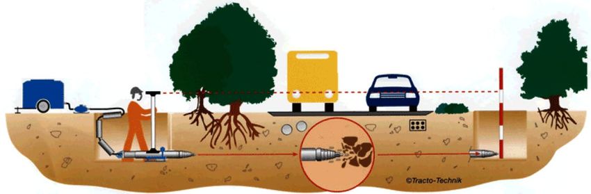
associated with utilities crossing sewer lines. Cross bores occur during the installation process of
a utility such as electric, cable/internet, water, and natural gas. Cross Bores primarily occur when
the utility is installed using boring techniques such as Horizontal Directional Drill (HDD) or
pneumatic drilling.
Danger
Cross Bores present serious risks to contractors, homeowners, and the community. Clearing sewer
blockages caused by Cross Bores can be especially dangerous. It is imperative to identify the cause
of a sewer blockage prior to clearing the blockage. There are documented instances of people
clearing cross bored sewer lines without prior inspection, rupturing a utility line and causing injury,
property damage, and even death.
Page 7DIGSAFE & CROSS BORES
Prevention
Contact Dig Safe® prior to any planned installations or digging. Dig Safe®, however, does not
identify the sewer line locations. When sewer line location and depth are unknown, open trenching
techniques will be utilized for gas installation. If all utilities cannot be located, installation should
be done using open trench methods of construction. Note: A sewer contractor can be contacted to
attempt to locate sewer lines prior to construction.
It is necessary to investigate any sewer blockages that occur prior to attempting to clear the
blockage. If unable to visually verify that the blockage has not been caused by a cross bored utility
Do Not attempt to clear the blockage with mechanical equipment. Call Dig Safe® and request an
emergency locate for utility lines. If it is shown that the gas utility crosses the known path of the
sewer line, contact VGS. A VGS technician will provide assistance to correct the problem.
Page 8LEGISLATION & GOVERNING CODES
SECTION 4: Legislation & Governing Codes
Applicable codes are listed below. If there is a conflict of rules, the company will make a final
decision applicable to the situation.
4.1 Federal
ANSI Z-223.1/NFPA 54 National Fuel Gas Code (applies to customer owned piping)
AGA Distribution Center
P.O. Box 79230
Baltimore, MD 21279-0230
https://www.nfpa.org/Codes-and-Standards/All-Codes-and-Standards/Free-access
Department of Transportation Title 49 CFR Part 192
Superintendent of Documents
U.S. Government Printing Office
Washington, DC 20402
49 CFR 192 - Transportation of Natural and Other Gas by Pipeline
4.2 State
Vermont Public Utility Commission Rules
Vermont Public Utility Commission
112 State Street
Montpelier, VT 05620-2701
https://puc.vermont.gov/about-us/statutes-and-rules/current-rules-and-general-orders
4.3 City & County
Local permit rules vary from town to town and city to city. Any questions about local excavation
permitting processes may be directed to the VGS Engineering and Construction Departments at
(802) 863-4511.
Page 9RIGHT-OF-WAY AGREEMENTS, LAND USE & ENCROACHMENTS
SECTION 5: Right-of-Way Agreements, Land Use, & Encroachments
5.1 Right-of-Way Agreements
A right-of-way agreement is an agreement by which a property owner grants permission to another
party to use a portion of his or her land for a specific purpose. VGS works with landowners to
secure a deed of easement, which outlines the rights of the parties and terms of the agreement. The
right-of-way gives VGS the right to construct, operate, and maintain its pipeline and related
facilities, which are necessary for the transmission, storage, and distribution of natural gas. VGS
also has the right of ingress and egress over the pipeline corridor. The right-of-way agreement or
easement grants VGS an interest in the property, and the easement is recorded in the appropriate
municipal land records. A deed of easement is a legal document. If the land is transferred, the
rights and responsibilities under the terms of the easement pass on to the new owner.
Most of VGS’s existing pipeline easements and rights were acquired through right-of-way
agreements granting VGS the right to construct, operate, maintain, repair, modify, alter, protect,
clear obstructions, change the size of, remove, replace, and access a pipeline, or pipelines, within
the easement area.
In cases of new installations, VGS may require an easement or right-of-way, which is needed prior
to installation of distribution mains and/or service lines. Our sales representative can supply you
with the required forms to initiate the easement documentation. Please provide us with the name
of the current property owner as soon as possible. If you have any questions or concerns, please
contact our Right-of-Way Department at (802) 863-4511 or email rowcorridor@vermontgas.com.
5.2 Land Use Information
Under the deed of easement, the landowner may use their land as they wish provided it does not
interfere with the rights granted to VGS to maintain and operate our pipeline. For safety purposes,
we require all landowners to notify VGS prior to any work on the right-of-way. Certain work on
the premises may unduly interfere with the safety of our pipeline. VGS cannot permit such work.
We have summarized some of these situations below:
1. No trees shall be planted within the confines of the right-of-way. We consider trees as those
plants that grow to an excess of five (5-feet) feet in height at maturity. Taller trees inhibit
access to the pipeline and their roots can damage the pipeline. Shrubs or bushes less than
five (5-feet) feet in height may be located on VGS’s right-of-way provided they are not
planted within ten (10-feet) feet of the pipeline, or between the pipelines in a multiple line
situation. In either of these cases, VGS will be glad to locate its pipeline for you. No
permanent planting of any type within ten (10-feet) feet of the pipeline is allowed. Please
note under the terms of the right-of-way agreement, VGS still reserves the right to remove
any trees, shrubs or other obstructions, without compensation, that may interfere with the
operation and maintenance of its facilities.
2. No earth shall be removed from the surface of the right-of-way, for such removal can
expose the pipeline to damage. Small amounts of fill may be added with VGS’s prior
approval, provided it is clean fill, free of rocks, stumps, and debris. No water impoundment
is allowed within VGS’s right-of-way.
Page 10RIGHT-OF-WAY AGREEMENTS, LAND USE & ENCROACHMENTS
3. No structures shall be located on the right-of-way. This includes, but is not limited to
houses, utility sheds, garages, swimming pools, house trailers, wells, sewer systems, etc.
VGS must be able to access and maintain the pipeline at all times. Permanent fences may
be located across the right-of-way if provisions are made for VGS crews and equipment
to gain access through them by proper placement of suitable gates. If you install a lock on
the gate, VGS must have its own set of keys or the combination.
4. Underground utilities crossing VGS’s pipeline shall be installed below the pipeline, with
a minimum of 12 inches of vertical clearance and 36 inches of horizontal clearance so as
not to interfere with the pipeline. Utilities include sewers, drain lines, water pipes, gas
pipes, underground electric or telephone cables, etc. These facilities are not to be placed
parallel to our pipeline within VGS’s right-of-way. Septic systems shall not be built on
VGS’s right-of-way.
5. No heavy equipment is to be moved across the right-of-way prior to notifying VGS.
Construction plans that affect VGS’s rights-of-way, as outlined in paragraph four (4) and five (5)
above, should be submitted for review and approval prior to the start of any construction project.
Bringing us into the early planning stages of your project will help to avoid delays and additional
costs.
5.3 Encroachments
Specifications and Requirements
1. An encroachment agreement is required whenever a permanent installation (e.g., utility
lines, pipelines, road crossings, above and below ground structures, sheds, swimming
pools, trees, berm, shrubs, etc.) or intrusive temporary activity (e.g., construction, logging,
mining, blasting, excavating) is approved to encroach into the right-of-way area.
2. The encroachment agreement must be executed by the landowner or party seeking to
encroach and VGS prior to the proposed activity or installation.
3. All encroachment agreements covering permanent installations will be recorded in the
appropriate municipal land records.
4. The encroachment agreements covering temporary encroachments will be recorded in the
land records at the discretion of VGS.
5. All encroachments require prior approval by VGS and may be denied or approved based
on a case-by-case basis. Project scope and proximity to the pipeline will be considered in
accepting or rejecting any proposed encroachment.
6. All encroachment agreements will be tailored to the specific permanent or temporary
encroachment.
7. It is our desire and right to keep a clear right-of-way that can be used by our maintenance
personnel.
8. VGS must be able to access the pipeline, cathodic protection, and other facilities along and
within its rights-of-way across your property in order to properly maintain and operate our
facilities in accordance with the United States Department of Transportation regulations.
Page 11RIGHT-OF-WAY AGREEMENTS, LAND USE & ENCROACHMENTS
VGS understands its responsibilities and will exercise its rights with a minimum of
inconvenience to you. Your safety and the safety of the public are our first consideration
and top priority. We appreciate your cooperation.
*Remember to call DigSafe® at 811 prior to any digging, demolition, blasting or excavation
activity.
Page 12GENERAL REQUIREMENTS FOR DEVELOPERS, CONTRACTORS &
BUILDERS
SECTION 6: General Requirements for Developers, Contractors &
Builders:
6.1 General Application and Scheduling Requirements
1. Individual service applications should be submitted at least 60 days before the required
installation date. In some instances, the exact requested installation date may not be known
when submitting the original application. In these cases, the installation request must be
made to the VGS sales representative at least three (3) weeks in advance.
2. VGS will provide excavation work during its normal construction year, which typically
runs from May 1st to November 15th, weather permitting. Excavation work outside of these
dates is primarily limited to maintenance of our existing system. Any excavation work
outside of these dates, including road crossings, will need to be performed by your
excavating contractor (subject to local permitting). (See Section 13 for Customer Dig
Guidelines.)
3. Certain permits may affect the schedule and are not in the control of VGS.
6.2 Site Plans and Site Preparation
Plans
1. VGS will need a reproducible site plan along with other pertinent drawings, and a copy of
the CAD file (.DGN, .DWG or .DXF format) of the site plan and utility plan.
2. Prior to submitting your site and/or utilities plan to VGS, please contact the Engineering
Department. They will inform you as to the proper location of gas mains and service lines
to be shown on your drawings.
3. Section 8 contains sketches of typical single and multiple meter sets to help you properly
locate your customer-owned fuel lines. Proposed meter locations must be submitted with
your site drawings.
Ledge
1. VGS does not generally excavate ledge unless it has been pre-approved.
2. If ledge is encountered, the developer shall remove the ledge that prohibits VGS from
achieving proper depth.
3. In ledge area, a minimum of six inches (6-inch) of sand padding will be applied around the
pipe with twelve inches (12-inch) on top of the pipe.
4. Only VGS-approved backfill material can be placed above the twelve inches (12-inch) of
sand padding. SAND FOR PADDING MUST BE FURNISHED BY THE
DEVELOPER OR SITE CONTRACTOR.
Page 13GENERAL REQUIREMENTS FOR DEVELOPERS, CONTRACTORS &
BUILDERS
Sleeves
1. VGS requires that a sleeve be installed in specified locations for all distribution main and
service line road crossings. VGS will open cut and backfill with the same material as
unpaved gravel road base if you prefer.
2. VGS will supply the sleeve material and mark the desired locations on a site plan.
3. Developer is to install the sleeves outside of the driveway cut, favoring the side of the lot
where the service is to be installed. If the service location cannot be determined at the time
of the sleeve installation, sleeves should be installed near the center of the lot frontage away
from the driveway curb cut.
4. It is the responsibility of the developers/contractors to supply field identification of the
location of the sleeves.
5. If the sleeves are unusable or cannot be located, it will be the developers' responsibility to
install a new sleeve, dig a trench or have the service drilled (if scheduling allows) at the
developer’s cost.
6. Sleeves shall be installed at a depth of three feet (3-feet) minimum below finish grade not
to exceed a maximum of four feet (4-feet). Any deviation from these depths will need VGS’
Operations Department approval.
7. Sleeves shall not be installed within twenty (20-feet) feet of any building or structure.
8. A sketch of a typical sleeve installation is enclosed (See Figure 6.1).
Site Preparation
1. If site conditions do not make it obvious where the proposed gas main should be located,
it is the responsibility of the developer to stake out the proposed gas main locations in the
field. If the developer chooses not to do so all relocations will be at developers cost.
Stakes showing the centerline and final elevation of roads or streets shall be installed and
maintained until construction is complete.
2. Finished grade elevations shall also be provided to assure proper depth of burial.
3. Foundations should be backfilled to within six inches (6-inch) of finish grade and the
proposed service route should be free of obstructions and within six inches (6-inch) of
finish grade before a service line is constructed. If not at finish grade, a horizontal mark
must be made on the foundation showing the finished grade to allow for proper height of
the gas meter.
4. To prevent future corrosion to the meter, care must be taken during subsequent grading to
ensure the gas meter is not buried or in contact with the earth and the gas riser is not buried
above the bury line. If finish grade results in either of these situations, contact VGS.
5. The developer, contractor or builder is responsible for supplying the sand used for padding
the pipelines in "customer dig" applications.
6. Developers, contractors and builders must notify VGS when the site will be ready. A three
(3) week minimum lead-time is required for scheduling construction of distribution main
Page 14GENERAL REQUIREMENTS FOR DEVELOPERS, CONTRACTORS &
BUILDERS
or service lines. Please contact the VGS Engineering Manager, at
(802) 863-4511 ext. 329 to schedule installation of gas mains and/or services. Please be
sure you have submitted the application for service with the sales representative prior to
calling to schedule the installation.
Page 15GAS MAINS & SERVICE LINES
SECTION 7: Gas Mains & Service Lines
VGS has committed to have all new gas facilities up to the outlet of the meter be reviewed and
stamped by a licensed professional engineer. VGS completes this review prior to construction.
7.1 Gas Mains
General Information
1. The gas main pipe will be installed by VGS or a qualified VGS contractor.
2. No one other than a VGS employee or qualified VGS contractor shall ever work on or
alter any part of the natural gas distribution facilities.
3. Gas main typically will be installed on the front side of buildings/houses between the
edge of the road and the R.O.W./property line. Preferably the main will be in the
greenbelt. Gas main will be installed parallel to the road edge.
4. No gas mains are to be installed behind buildings/houses unless approved by the VGS
Operations Department.
Conditions for Installing Gas Facilities
1. For direct buried gas lines and all other methods of construction, VGS requires a minimum
three feet (3-feet) of horizontal separation from all other utilities as depicted on figure 7.1.
Other utilities may require as much as 10 feet (10-feet) of separation.
2. A minimum of twelve inches (12-inch) of vertical separation between gas lines and other
utilities must be maintained at all times.
3. Locator wire for plastic gas lines shall not be in contact with any utility or underground
structure.
4. VGS prefers that water mains, water laterals, sewers, and storm drains be installed prior to
the installation of the gas mains and service lines.
5. The area in which the gas facilities are to be located should be made easily accessible and
allow for safe working conditions.
7.2 Gas Service Lines
General Information
1. Gas services will be installed by VGS or a qualified VGS contractor.
2. No one other than a VGS employee or a qualified VGS contractor should ever work on or
alter any part of the natural gas distribution facilities.
3. Service lines should be installed perpendicular from the main to the meter location. Service
risers and meters will be located on either side or in front of a building/house. Except for
corner buildings, services will be installed off the gas main on the street for which the
address of the building/house is on.
Page 16GAS MAINS & SERVICE LINES
Back
House
Front
Acceptable
Service Locations
Driveway
Natural Gas Main
Street
4. Corner buildings may have a service coming off either street with preference to the street
which it is addressed on. The length of the service and whether a road crossing is required
should also be considered.
5. Gas will be supplied to each building through a single service line or customer-owned fuel
line unless otherwise approved by the VGS Operations Department.
6. For buildings with two (2) or more services, a Multiple Services sign will be installed at
each riser. A sign with the location of the service risers will also be required at each riser
on new service installations.
7. Service risers should be attached to the foundation with a support bracket where building
foundation conditions allow.
Page 17GAS MAINS & SERVICE LINES
Page 18REGULATORS, METERS, PIPING & BARRICADES
SECTION 8: Regulators, Meters, Piping & Barricades
8.1 Regulators
General Information
Gas pressure regulators will be set to deliver seven inches (7-inch) Water Column (W.C.)
downstream of the meter unless a request for elevated gas pressure is approved (see section below).
Regulators must be separated from ignition sources, air intakes, and vents to comply with federal
regulations.
a) A minimum of three feet (3-feet) of horizontal separation is required between the gas
pressure regulator or meter and electric meter or other source of ignition.
b) A minimum of three feet (3-feet) of radial separation is required between gas pressure
regulators and building openings, , air-conditioning condensing units, make-up air units,
exhaust vents from heaters, exhaust vents from water heaters, exhaust vents from dryers,
or from any source of excessive moisture.
c) A minimum ten feet (10-feet) of radial separation is required for gas pressure regulators
from forced air intakes unless equipped with full lockup over-pressure shut-off. See Figure
8.1 for a design depicting regulator location restrictions.
d) Refer to Figures 8.3 and 8.4 for designs of typical single and multiple meter sets on to help
you properly locate your fuel lines. Proposed meter locations must be submitted with your
site drawings.
Elevated Gas Pressure
Gas pressure greater than seven inches (7-inch) W.C. is considered elevated pressure. Elevated
pressure may be delivered downstream of the meter in the following situations, upon approval by
the VGS Operations Department:
a. Total customer volume requirement on a single meter exceeds three (3) MBTUs/hour
b. Temporary heat for construction
c. Special manufacturing loads
d. Elevated pressure requires a rotary meter instead of a traditional meter. The active level
of elevated pressure will determine the size of the rotary meter required. See Figures
8.5, 8.6, and 8.7 for the designs of a 5M, 2M/3M, and 7M Rotary Meter.
When a request for elevated pressure is approved, VGS will provide five (5) psig downstream of
the meter.
The customer is responsible for the following:
• Pressure reduction from five (5) psig or less to the equipment utilization pressure
• Provide and maintain the overpressure protection equipment
Elevated pressure piping must be welded and labeled according to ANSI/ASME A13.1 pipe
marking guide to indicate elevated pressure in piping.
Page 19REGULATORS, METERS, PIPING & BARRICADES
8.2 Meters
Speci�ications and Requirements:
a) Proposed meter locations shall avoid areas of potential snow and ice buildup. Avoid
locating meters under an eave of the building where snow or ice water might fall.
Avoid locating meters in areas where snowplows and snow blowers will cover the
meter with snow.
b) The VGS’s Operations Department shall have final approval of meter locations.
c) Proposed meter locations should avoid areas of vehicular traffic. If this cannot be
avoided, VGS will require the customer or builder to install barriers approved by VGS
to protect the service and meter set at the customer’s cost. See Section 8D.
d) If a customer or builder requests a location which requires meter set protection, they
shall bear the cost of the protection. No meters will be turned on until above
measures are satisfied.
e) VGS must have access to the meter, at all times, for the reasons of emergency response,
safety, meter reading, and maintenance concerns.
• Any installation which deviates from the above requirements must be approved
by the Operations Department. In the event it is deemed that all possible service
locations on the front or side of the structure have been exhausted, the
contractor, builder, or developer may be given the option to pay to have the
service installed in the rear of the structure. The current per foot charge will be
assessed, as measured from the nearest rear corner to the termination point, with
a specified minimum charge.
The cost of relocating services after installation will be passed on to the contractor, developer
or homeowner.
8.3 Piping
Speci�ications and Requirements
a) All customer owned piping, piping on the outlet side of the meter, must meet the NFPA 54
Natural Fuel Gas Code, as adopted by the State of Vermont, referenced in Section 4.
b) All VGS-owned piping (piping on the inlet side of the meter) must meet the Department
of Transportation Title 49 CFR Part 192, as adopted by the State of Vermont, referenced
in Section 4.
c) All piping exposed to the outside air must be protected from atmospheric corrosion. Two
common methods of protection are to use galvanized piping or to paint all exposed piping.
d) Piping installed above ground shall be securely supported and located where it will be
protected from physical damage.
e) Horizontal piping should be supported with an angle bracket. If an angle bracket cannot be
used than a split ring bracket can be used.
f) Call the VGS Service Department at (802) 863-4511 with any questions regarding the
support of above ground piping.
Page 20REGULATORS, METERS, PIPING & BARRICADES
Support of Piping
Steel Pipe, Nominal Size of Pipe (in.) Spacing of Supports (ft.)
½ 6
¾ or 1 8
1 ¼ or larger (horizontal) 10
1 ¼ or larger (vertical) Every floor level
For SI units: 1 ft. = 0.305 m.
Manifolds
Inches to service from
Manifolds
end of manifold
1 meter 14-inch
2 meter 34-inch
3 meter 50-inch
4 meter 66-inch
5 meter 82-inch
Gas Meter Sizing
Size Min. Flow Max. Flow
AC250 1 320
Sensus R-275 1 410
AL425 320 550
AL630 550 900
AL800 800 1,100
AL1000 1,000 1,500
D1000 800 1,500
2M 1,400 1,900
3M 1,900 2,900
5M 2,900 4,900
7M 4,900 6,900
Page 21REGULATORS, METERS, PIPING & BARRICADES
Regulators
Max. Flow Internal
Body Orifice Max. Flow scfh
Size O.P.S.O. scfh @ 25 Relief & or
(inch) (inch) @ 60 psi
psi OPSO
American 1213 B 3/4 1/8 No 475 700 Full
1/8 x
American SR 113 3/4 No 500 1100 Full
3/16
Itron B42R 3/4 1/8 x3/16 No 550 1150 Full
Itron B42R ¾x1¼ 1/8x 3/16 No 550 1150 Full
American 1813 C 1 1/8 x3/16 No 575 1100 Full
American 1843 partial w/
1 3/16 Yes 1,250 2,400
B2 OPSO
American 1883
1 3/16 Yes 1,250 2,400 OPSO
B2
American 1813 B 2 ¼ No 2,500 4,500 Full
partial w/
American 1843 2 ½ Yes 9,050 17,400
OPSO
American 1883 2 ½ Yes 9,050 17,400 OPSO
Page 22REGULATORS, METERS, PIPING & BARRICADES
Figure 8-1, Meter Clearances
Page 23REGULATORS, METERS, PIPING & BARRICADES
Figure 8.2, Typical Service
Page 24REGULATORS, METERS, PIPING & BARRICADES
Figure 8.3, AC-250 Single Meter Manifold Detail
Page 25REGULATORS, METERS, PIPING & BARRICADES
Figure 8.4, AC-250 Multiple Meter Manifold Detail
Page 26REGULATORS, METERS, PIPING & BARRICADES
Figure 8.5, D1000 Single Meter Manifold
Page 27REGULATORS, METERS, PIPING & BARRICADES
Figure 8.6, AC-250 Multiple Meter Manifold Detail
Page 28REGULATORS, METERS, PIPING & BARRICADES
Figure 8.7, AC-250-425-630 Multi Meter Manifold Detail
Page 29REGULATORS, METERS, PIPING & BARRICADES
Figure 8.8, 2M-3M Rotary Meter Manifold Detail
Page 30REGULATORS, METERS, PIPING & BARRICADES
Figure 8.9, 5M Rotary Meter Manifold Detail
Page 31REGULATORS, METERS, PIPING & BARRICADES
Figure 8.10, 7M Rotary Meter Manifold Detail
Page 32REGULATORS, METERS, PIPING & BARRICADES
8.4 Barricades/Barriers:
1. Typical barriers are set a minimum of four feet (4-feet) into the ground in concrete and standing
above the top level of the meter set, within three feet (3-feet) of a driveway, parking lot or
sidewalk. See Figure 8.11. As a general rule, install barricades approximately four feet (4-feet)
from the building’s exterior including a twelve-inch (12-inch) clearance from the front of the
meter.
• Residential: Two-inch (2-inch) Diameter SCH. 80 Steel Post. Minimum three feet (3-feet)
above grade. Concrete filled, painted, with a minimum ten-inch (10-inch) diameter
Sonotube® or concrete base.
• Small Commercial and Apartment Complexes: Four-inch (4-inch) Diameter SCH. 80
Steel Post. Minimum three feet (3-feet) above grade. Concrete filled, painted, with a
minimum twelve-inch (12-inch) diameter Sonotube® or concrete base.
• Large Commercial and Industrial: Six Inch (6-inch) Diameter SCH. 80 Steel Post.
Minimum four feet (4-feet) above grade. Concrete filled, painted, with a minimum twenty-
inch (20-inch) diameter Sonotube® or concrete base.
Note: Two (2) posts should be used when the maximum distance between posts are four feet
(4-feet) or less. A third post must be installed when greater than four feet (4-feet).
2. In areas of potential vandalism, the customer may be required to provide a secure six foot
(6-feet) tall chain link fence with a gate that can be locked. VGS will need a key or combination
for access.
3. For information on meter pads, barrier placement, installations not covered above and other
support methods contact the Operations Department at (802) 863-4511.
Page 33REGULATORS, METERS, PIPING & BARRICADES
Figure 8.11, Barricade Requirements
Page 34REGULATORS, METERS, PIPING & BARRICADES
8.5 Gas Meter Recess
1. All entrances/penetrations into building shall be sealed properly.
2. Depth of recess must be 24-inches.
3. A four-inch (4-inch) diameter sleeve is required if paving during construction.
4. For a detailed design of the proper recess for a gas meter, see Figure 8.12.
Page 35REGULATORS, METERS, PIPING & BARRICADES
Figure 8.12, Meter Recess
Page 36REGULATORS, METERS, PIPING & BARRICADES
8.6 Gas Meter Enclosures
1. All enclosure side against building shall be gas tight as to prevent gas migration into
building.
2. Provide a minimum of one hundred and twenty square inches (120 sq. in.) of free air space
at the top and bottom of enclosure (if free air space of louver is unknown, use 75% of
calculated surface area).
3. Enclosure shall be readily accessible for access and maintenance.
4. Either single or double door is allowed but must be no smaller than forty inches (40-inches)
wide by
thirty-six inches (36-inches high).
For a detailed design of a proper enclosure see Figure 8.13.Figure 8.13, Meter Enclosure
Page 37REGULATORS, METERS, PIPING & BARRICADES
Page 38WORKING IN THE VICINITY OF GAS LINES
SECTION 9: Working in the Vicinity of Gas Lines
9.1 Damages to VGS piping system:
1. If ANY VGS LINE IS DAMAGED AND LEAKING (OR POSSIBLY LEAKING),
CALL 911. After calling 911, notify VGS at 1-800-639-8081 or ((802) 863-4511 to report
the emergency. Do not attempt to contact individuals at VGS.
2. All other damage should be reported to VGS at 1-800-639-8081 or
(802) 863-4511.
3. All damages to VGS-owned facilities and gas lines shall be immediately reported to VGS.
The damages shall be repaired by VGS maintenance personnel prior to backfilling.
4. All coating damage to steel gas lines shall be reported immediately to VGS. Coating breaks
shall be repaired by either VGS maintenance personnel or by contractors with VGS
inspectors prior to backfilling.
5. All breaks and damages to tracer wire for plastic pipe shall be reported to VGS. The breaks
and damages shall be repaired by either VGS personnel or by contractors with VGS
inspector prior to backfilling.
6. All damages to VGS cathodic protection facilities and cathodic protection test facilities
shall be reported to VGS. The damages shall be repaired and tested by VGS personnel or
by contractors with VGS inspectors prior to backfilling.
7. All damages to VGS test, locator, and valve boxes shall be reported to VGS. Either VGS
personnel or contractors with VGS inspectors shall repair the damages. All VGS test,
locator, and valve boxes shall remain accessible after any grade changes. Contact VGS for
any boxes that need to be raised due to a grade change. No boxes shall be under cover.
Specifications and Requirements for All VGS Pipe
1. Contractors are to conform to VGS Requirements listed in Section 7A.
2. No concrete shall be in contact with gas lines.
3. Extra coating required for steel gas lines shall be done by VGS personnel or contractors
with VGS inspectors prior to backfilling.
4. All exposed gas lines shall be padded with six inches (6-inch) minimum of sand or a stone
free material prior to backfilling unless otherwise stated by VGS specifications or
drawings.
5. If blasting within one hundred foot (100-foot) radius of Gas Facilities, notify VGS prior to
and after blasting. VGS will work with the blasting contractor prior to and after blasting to
ensure the safety of the public and all parties involved. Proper arrangements shall be made
between the blasting contractor and VGS to coordinate schedules.
If the blasting vibrations will be at or above two inches (2-inch) per second (IPS) Peak Particle
Velocity and the two (2) IPS peak particle velocity is going to be seen at the pipelines, a site
meeting between the blasting contractor and a VGS Operations Manager or Supervisor will be
Page 39WORKING IN THE VICINITY OF GAS LINES
held to discuss the safety of VGS facilities.
If the blasting in the area is below the two (2) IPS peak particle velocity, VGS will leak survey
the area before and after the blasting.
Specifications and Requirements for VGS Transmission Pipe:
1. Notify VGS of any excavations within one hundred (100 feet) of a VGS Systems’
Transmission Pipeline.
2. Any areas of exposed transmission pipe should be reported to VGS.
Page 40INFILL SERVICES & NATURAL GAS SERVICE LINE INSTALLATION
Section 10: Infill Services & Natural Gas Service Line Installation
10.1 In�ill Services
The following are prerequisites of service which the applicant subscriber(s), or its duly authorized
officer/agent, agrees to meet:
1. The riser location chosen shall be no less than three feet (3-feet) from existing or planned
electrical panels or meters, and windows. Meters will not be installed under any drip
locations or areas exposed to vehicular traffic without proper protection. (See Figures 8.2
and 8.5).
2. Grade shall be within six inches (6-inch) of finished grade from street to building and
finished grade shall be marked on the foundation of the building with a horizontal line.
3. All materials shall be cleared from facilities location, including trees and bushes.
4. Meter protection and/or pad must be in place, if required.
5. No ledge removal is required. (Ledge removal will require a negotiated excess charge for
construction.)
6. No frost in the ground. (Frost in ground will require a negotiated excess charge for
construction.)
7. No other parallel utilities shall be within three feet (3-feet) horizontally or one foot (1-feet)
vertically of facilities location selected.
10.2 Natural Gas Service Line Installation
A. Prior to Construction
VGS personnel will pre-mark the construction area with white flags and/or paint. The One Call
Center, DigSafe® #811, will be called to locate and map underground facilities within the pre-
marked area. Privately owned sewer lines, water lines, irrigation lines, power, lighting and electric
dog fences may not be clearly identified which sometimes makes them difficult to locate. To help
identify sewer line locations, VGS personnel will attempt to document where the sewer line exits
the structure and any other relevant information that may be provided by the resident in regard to
underground utilities during a site visit. Locations having potential sewer line conflicts during the
pre-marking process may require further investigation. The more potential conflicts, the higher the
probability of that open trenching will be required.
B. Construction Methods
Open Trenching – This technique is the preferred method of installation when the locations of
underground utilities such as water or sewer are unknown. An excavator will open a trench roughly
one foot (1-feet) wide and three feet (3-feet) deep from the street up to your home or business in
which to install the gas line. Once the line is installed, the trench will be backfilled and tamped
(packed down).
Plowing – A technique that uses a machine that pulls along a sharp blade which slices through the
ground ahead of a metal chute which places the pipe at any desired depth. An expander behind the
Page 41You can also read