VISION 1000 CONFIGURATION TOOL - USER GUIDE - Document revision 1.17 Last revised: June 8, 2021 - Appareo
←
→
Page content transcription
If your browser does not render page correctly, please read the page content below

VISION 1000
CONFIGURATION TOOL

    USER GUIDE

      Document revision 1.17
     Last revised: June 8, 2021
Vision 1000 Configuration Tool User Guide
                                                                                   Revision 1.17
                                                                 Date Last Revised: June 8, 2021

                Vision 1000 Configuration Tool User Guide
                  © 2010 - 2021 Appareo Systems, LLC. All Rights Reserved.

Vision 1000 Configuration Tool User Guide. All content within is copyrighted by Appareo
Systems, LLC, and may not be reprinted without permission.

The content of this guide is furnished for information use only, is subject to change without
notice, and should not be construed as a commitment by Appareo Systems, LLC. Appareo
assumes no responsibility or liability for any errors or inaccuracies that may appear in the
information content contained in this overview document.

Appareo, Appareo Systems, the Appareo logo and Vision 1000 are either registered trademarks
or trademarks of Appareo Systems, LLC. All other trademarks and registered trademarks are
the sole property of their respective owners.

Appareo Systems, LLC, 1810 NDSU Research Circle North, Fargo, ND 58102 USA.

                            Visit us on the web at www.appareo.com.
                          Questions? E-mail us at support@appareo.com.

                                Technical Assistance
Visit appareo.com/vision1000-docs for the most recent versions of Vision 1000 documentation.

If you require support while installing or using the Vision 1000, please contact Appareo using
the information below.

E-mail:
support@appareo.com

Telephone:
+1 701 356 2200

Appareo support staff is available Monday through Friday, 8 a.m. to 5 p.m. U.S. Central Time
(CT). Appareo is closed during some U.S. federal holidays.

600890-000004                                                                            Page 2 of 22
Vision 1000 Configuration Tool User Guide
                                                                                                                   Revision 1.17
                                                                                                 Date Last Revised: June 8, 2021

                                                      Table of Contents
TECHNICAL ASSISTANCE ......................................................................................................................... 2
1     DEFINITIONS ....................................................................................................................................... 6
2     INTRODUCTION .................................................................................................................................. 7
3     INSTALL THE VISION 1000 CONFIGURATION TOOL ...................................................................... 8
4     CONNECT TO THE VISION 1000 ........................................................................................................ 9
    4.1      CONFIGURE THE NETWORK SETTINGS FOR CONNECTING TO THE VISION 1000 .................................... 9
    4.2      DISABLE NETWORK CONNECTIONS ................................................................................................. 10
    4.3      CONNECT TO THE VISION 1000 ...................................................................................................... 11
5     LOG IN TO THE VISION 1000 CONFIGURATION TOOL ................................................................ 12
6     VISION 1000 CONFIGURATION TOOL OVERVIEW ........................................................................ 13
    6.1      OVERVIEW TAB .............................................................................................................................. 13
    6.2      CONFIGURE TAB ............................................................................................................................ 15
    6.3      BUILT IN TEST TAB ......................................................................................................................... 16
    6.4      DOWNLOAD TAB ............................................................................................................................ 17
7     CONFIGURE THE VISION 1000 ........................................................................................................ 18
    7.1      ZOOM IN OR ZOOM OUT .................................................................................................................. 18
    7.2      CONFIGURE THE IMU ZERO POINT .................................................................................................. 19
    7.3      ENTER THE TAIL NUMBER (OPTIONAL) ............................................................................................. 21
    7.4      MUTE AMBIENT AND LINE-IN SOUND ................................................................................................ 21
8     UNDERSTANDING THE VISION 1000 LED STATUS LIGHT .......................................................... 22

600890-000004                                                                                                                              Page 3 of 22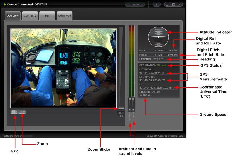
Vision 1000 Configuration Tool User Guide
                                                                                                       Revision 1.17
                                                                                     Date Last Revised: June 8, 2021

                                                 Table of Figures
Figure 1: Vision 1000 Configuration Tool Overview .................................................................... 7
Figure 2: Vision 1000 IP address configuration settings ............................................................. 9
Figure 3: The E1 Ethernet port on the back of the Vision 1000 .................................................11
Figure 4: Logging into the Configuration Tool ............................................................................12
Figure 5: Overview Tab .............................................................................................................13
Figure 6: The Grid overlaid on a frame capture .........................................................................14
Figure 7: Configure Tab ............................................................................................................15
Figure 8: Built in Test Tab Summary .........................................................................................16
Figure 9: Download Tab Summary ............................................................................................17
Figure 10: Zoom View Area.......................................................................................................18
Figure 11: IMU Zero Point Configuration ...................................................................................19
Figure 12: A helicopter with -20° roll (left) and with 20° roll (right) .............................................19
Figure 13: A helicopter with 20° pitch (up) and with -20° pitch (down) .......................................19
Figure 14: Configuring Yaw Offset Angle ..................................................................................20
Figure 15: IMU Zero Point Configuration Error ..........................................................................20
Figure 16: LED Status Light Location ........................................................................................22

NOTE: Graphics used in this document are for illustrative purposes only. Vision 1000 images
may vary depending on aircraft model and Vision 1000 version.

600890-000004                                                                                                           Page 4 of 22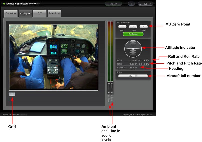
Vision 1000 Configuration Tool User Guide
                                                                                  Revision 1.17
                                                                Date Last Revised: June 8, 2021

                                Record of Revision
Revision                                                                  Revision     Inserted
                              Change Description
Number                                                                       Date         By
  1.0      Initial Release                                                1/18/2010      CJS
   1.1     Second release                                                 4/09/2010      CJS
   1.2     Third release                                                  4/29/2010      CJS
   1.3     Fourth release                                                 7/13/2010      CJS
   1.4     Fifth release                                                   9/9/2010      CJW
   1.5     Sixth release                                                  12/28/2010     CJW
           Added operating system category to the Minimum
   1.6                                                                    3/10/2011      CJW
           Systems Requirement table
           Edited instructions for how the Vision 1000 Configuration
   1.7     Tool password is received in the To Log In To the Vision       6/14/2011      CJW
           1000 Configuration Tool section
           Changed Figure 8 (Built in Test Tab Summary). Add
   1.8     cross-reference to Vision 1000 Configuration Overview          8/19/2011      CJW
           document
           Removed software version and serial numbers from all
   1.9     screenshots. Modified graphic displaying Vision 1000 E1        10/28/2011     CJW
           and P1 ports
           Added note to beginning of To configure the network
           settings for connecting to the Vision 1000 section to cross-
  1.10                                                                    2/23/2012      CJW
           reference for Configuration Overview document for
           Windows Vista and Windows 7 operating systems
  1.11     Revised roll, pitch, and yaw graphics                          2/29/2012      CJW
  1.12     Added Operator sign-in screen and instructions                 4/19/2012      CJW
           Added instructions for configuring portable computers with
  1.13     Windows Vista and Windows 7 operating systems. Made            7/30/2014      CJW
           minor formatting changes throughout. Changed logo.
           Revised “Install the Vision 1000 Configuration Tool”
  1.14                                                                     2/9/2015      CJW
           instructions. Expanded troubleshooting section.
           Fixed network configuration settings, added Windows 10
  1.15                                                                    2/14/2017      AAL
           information, removed obsolete doc reference
  1.16     Changed network settings instructions and IP address            9/08/17       AAL
  1.17     Added instructions to disable other network connections         6/08/21       AAL

600890-000004                                                                          Page 5 of 22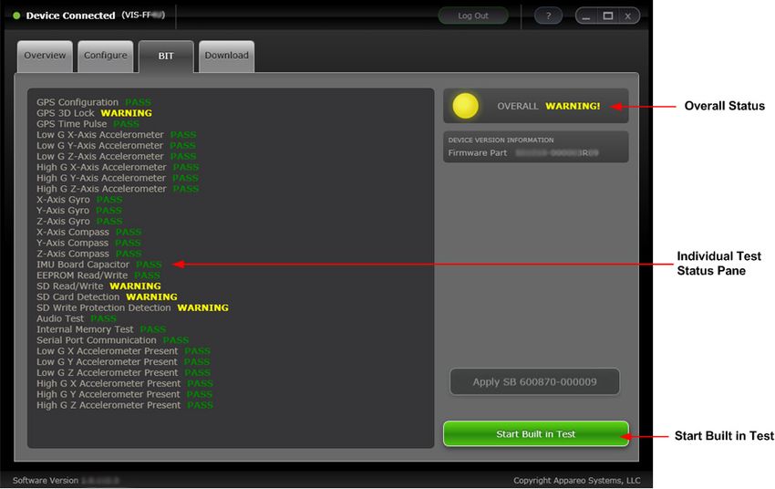
Vision 1000 Configuration Tool User Guide
                                                                               Revision 1.17
                                                             Date Last Revised: June 8, 2021

1 Definitions
Coordinated Universal Time (UTC) – A universal reference time based on International Atomic
Time. UTC is more accurate than Greenwich Mean Time, as it measures within a fraction of a
second.

Zoom View Area – A user-defined area of the main window that is magnified and displayed on
the right pane of the Overview Tab window.

                      Minimum System Requirements
         Category                       Minimum                     Recommended
                                 DirectX 9.0+ w/hardware        DirectX 9.0+ w/hardware
      Video capabilities
                                       acceleration                   acceleration
      Video capabilities              128+ MB RAM                    128+ MB RAM
   Central Processing Unit
                                    Pentium 4 3.2 GHz                  Core 2 Duo
            (CPU)
          Memory                           2 GB                           3 GB
    Available Disk Space                  25 GB                          25 GB
                                                              Windows XP, Windows Vista,
                                  Windows XP, Home or          Windows 7, Windows 8, or
     Operating System                  Professional                  Windows 10
                                 U.S. English version only       Home or Professional
                                                               U.S. English version only

600890-000004                                                                       Page 6 of 22
Vision 1000 Configuration Tool User Guide
                                                                                   Revision 1.17
                                                                 Date Last Revised: June 8, 2021

2 Introduction
The Vision 1000 Configuration Tool is a software application that allows users to quickly and
efficiently configure the Vision 1000. Use the Configuration Tool to adjust and configure the
Vision 1000, view Built in Test (BIT) results, and to download log files from the Vision 1000’s
internal memory. When a Configuration Tool user connects a portable computer (such as a
laptop) to the Vision 1000, he or she will see a real-time configuration display. This display
allows users to know exactly how the images recorded and saved to the Vision 1000’s memory
will display.

The Configuration Tool has four tabs for performing different actions: the Overview tab,
Configure tab, BIT tab, and Download tab. Each of these tabs is described later in the user
guide. The connection status between the Vision 1000 and the Vision 1000 Configuration Tool
is displayed at the top of the screen, along with the serial number of the Vision 1000 the device
is connected to.

                        Figure 1: Vision 1000 Configuration Tool Overview

600890-000004                                                                           Page 7 of 22
Vision 1000 Configuration Tool User Guide
                                                                                  Revision 1.17
                                                                Date Last Revised: June 8, 2021

3 Install the Vision 1000 Configuration Tool
NOTE: The Vision 1000 Configuration Tool must be installed while logged into an administrator
account on the computer.
   1. In an Internet web browser, navigate to www.appareo.com/account
   2. Type your Appareo web account user name and password in the appropriate fields and
      click Submit to sign in.
          i.  If you have not yet created a user account, click Click here to create a new
              account. Follow the on-screen instructions.
         ii.  If you have forgotten your username or password, click the Forgot your
              username or password link. Follow the on-screen instructions.
        iii.  If you continue to have problems signing in, click the contact us link and follow
              the on-screen instructions.
   3. Click the Add Product link.
   4. Select Vision 1000 Configuration Tool from the drop-down menu and type the product
      key. Click Submit. The Vision 1000 Configuration Tool will be added to the account’s
      product history, which is viewable on your account Home page.
          i.  The Configuration Tool product key was included in the Vision 1000 installation
              kit. If you did not receive the Configuration Tool product key or have misplaced,
              please contact Appareo for assistance.
   5. Click the Download link for the Vision 1000 Configuration Tool product on your account
      Home page. Follow the on-screen instructions to download the software file.
   6. By default, the program will install to C:\Program Files\Appareo\Vision 1000
      Configuration Tool. If you want to install the program in a different location on the
      computer, click Browse… and navigate to your desired installation location. Click Install
      when finished.
   7. Click Finish to close the Vision 1000 Configuration Tool Installation Wizard.

   To open the Configuration Tool after installation, double-click the    logo on the desktop,
   or click the Windows Start button on the lower left corner of your screen, click All
   Programs, point to Appareo, point to Vision 1000 Configuration Tool, and click
   Configuration.

NOTE: The Configuration Tool may be downloaded multiple times and may be installed on
multiple computers.

600890-000004                                                                         Page 8 of 22
Vision 1000 Configuration Tool User Guide
                                                                                   Revision 1.17
                                                                 Date Last Revised: June 8, 2021

4 Connect to the Vision 1000
To configure and maintain the device, you must connect the Vision 1000 to a portable computer
that is running the Configuration Tool.

4.1    Configure the network settings for connecting to the Vision 1000
As the Vision 1000 is configured with a static IP address, the portable computer will need to be
configured to a compatible IP address to allow the Configuration Tool to communicate with the
Vision 1000.

                     Figure 2: Vision 1000 IP address configuration settings

   1. Navigate to the network connections settings page.
      • Windows XP:
           a.    Click the Windows Start button on the lower left corner of the desktop.
           b.    Click Control Panel and click Network Connections.
      • Windows Vista:
           a.    Click the Windows Start button on the lower left corner of the desktop.
           b.    Click Control Panel and click Network & Sharing Center.
           c.    Click Manage network connections on the left side of the screen.
      • Windows 7:
           a.    Click the Windows Start button on the lower left corner of the desktop.

600890-000004                                                                           Page 9 of 22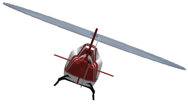
Vision 1000 Configuration Tool User Guide
                                                                                     Revision 1.17
                                                                   Date Last Revised: June 8, 2021

             b.      Type “Network Connections” into the search bar and click View Network
                     Connections.
        • Windows 8 and Windows 10:
               a.    Click the Windows Start button on the lower left corner of the computer’s
                     desktop.
                     NOTE: If you don’t have a Start button, move your cursor to the lower left
                     corner of the desktop and you should see the Start menu shortcut.
               b.    Click Settings or navigate to the Settings menu.
               c.    Click Network and internet.
               d.    Click Change adapter settings.
   2.   Right-click Ethernet (Windows 8, 10) or Local Area Connection and click Properties.
   3.   Click Internet Protocol Version 4 (TCP/IPx4) or Internet Protocol (TCP/IP) (Windows
        XP) and click Properties.
   4.   If there is an existing IP address listed, take note of it. Original settings will have to be
        restored after configuration has been completed.
   5.   Select Use the following IP address, and type the following information in the
        respective fields:
        • IP address: 192.168.16.200
        • Subnet mask: 255.255.255.0
        • Default gateway: 192.168.16.1
   6.   Click OK to save the network changes.
        NOTE: Remember to restore the portable computer’s original property settings once you
        have finished configuring the Vision 1000 (see Step 4).

4.2     Disable Network Connections
Disable network connections to make sure that the computer can connect to the flight data
recorder.
   1. Navigate to the network connections settings page.
       a.   Click the Windows Start button on the lower left corner of the computer’s desktop.
        NOTE: If you don’t have a Start button, move your cursor to the lower left corner of the
        desktop to see the Start menu shortcut.
      b.    Click Settings or navigate to the Settings menu.
      c.    Click Network & internet.
   2. Click Ethernet on the left navigation. Make sure that it says Not connected. If it shows
      an Ethernet connection, unplug the Ethernet cable from the computer.
   3. Click Wi-Fi on the left navigation. Disable the W-Fi switch at the top of the screen.

600890-000004                                                                             Page 10 of 22
Vision 1000 Configuration Tool User Guide
Revision 1.17
Date Last Revised: June 8, 2021
4.3 Connect to the Vision 1000
The Vision 1000 will need to be powered on during configuration. Given that the Vision 1000
draws its power from the aircraft, the aircraft must also be powered on or the Vision 1000 must
be connected a portable power source. While the Vision 1000 is starting up, a blue LED located
behind the SD card door will illuminate. After it has finished its startup, the LED will switch to
green. Once the LED has been green for approximately two minutes, you may connect to the
Vision 1000.
To connect a portable computer to a Vision 1000:
1. Insert the appropriate end of the Ethernet harness into the computer’s Ethernet port.
2. Connect the other end of the Ethernet harness to the Vision 1000’s E1 port, as shown in
Figure 3 below.
Figure 3: The E1 Ethernet port on the back of the Vision 1000
IMPORTANT: In order for the changes you make with the Configuration Tool to take effect, you
must “power cycle” the Vision 1000 once you have finished configuration. To power cycle the
Vision 1000:
1. Open the circuit breaker labeled Camera, located on the aircraft’s main circuit
breaker panel, to power off the Vision 1000.
2. Close the circuit breaker labeled Camera to power on the Vision 1000.
3. Observe the Vision 1000’s status LED light, located behind the SD card access door
a. While the Vision 1000 is starting up, the LED status light will be solid blue for
several minutes.
b. Once the Vision 1000 has properly booted up, the LED status light will be
solid green. This signifies that the Vision 1000 is ready to record flight data.
600890-000004 Page 11 of 22Vision 1000 Configuration Tool User Guide
Revision 1.17
Date Last Revised: June 8, 2021
5 Log in to the Vision 1000 Configuration Tool
Figure 4: Logging into the Configuration Tool
1. Ensure the Configuration Tool is connected to a Vision 1000 and the Vision 1000 is
powered on (the status LED will be solid green if the Vision 1000 is powered on).
2. Wait until the Vision 1000 status light is green and has the text “Device Connected.”
3. Ensure that Operator is selected from the role field.
4. Type the password in the Password field: h2StAste.
5. Click Login.
600890-000004 Page 12 of 22Vision 1000 Configuration Tool User Guide
Revision 1.17
Date Last Revised: June 8, 2021
6 Vision 1000 Configuration Tool Overview
6.1 Overview tab
The Overview Tab displays a live feed of images as they are collected from the Vision 1000. It
may be used to quickly determine if the Vision 1000 is correctly configured.
Figure 5: Overview Tab
Inertial Measurements – Displays the real-time data of the IMU
Attitude Indicator – Displays the current roll and pitch of the aircraft in an analog form.
Digital Roll and Roll Rate – Displays the current roll (in degrees) and roll rate (in
degrees per second) of the aircraft in digital form.
Digital Pitch and Pitch Rate – Displays the current pitch (in degrees) and pitch rate (in
degrees per second) of the aircraft in digital form.
Heading – Displays the current heading of the aircraft in degrees.
GPS Status – Indicates if the Vision 1000 GPS is in one of four modes: 3D Fix mode, 2D Fix
mode, Time Fix Only mode or No Fix mode. These modes are described below:
3D Fix mode – The GPS receiver is able to lock with multiple satellites and calculate the
aircraft’s current location (latitude and longitude) and provide Coordinated Universal
Time (UTC).
2D Fix mode – The GPS receiver is able to lock with only one satellite and calculate the
aircraft’s current location (latitude and longitude) and provide UTC. The latitude and
longitude of the aircraft’s current location may be less accurate than if the device were
able to receive signal from multiple satellites.
Time Fix Only mode – The GPS receiver is only able to provide UTC, but not location.
600890-000004 Page 13 of 22Vision 1000 Configuration Tool User Guide
Revision 1.17
Date Last Revised: June 8, 2021
No Fix mode – The GPS receiver is unable to lock with any satellites and is unable to
calculate the aircraft’s current location or provide UTC.
GPS Measurements – Displays the current latitude and longitude from the Vision 1000’s GPS
receiver in degrees, minutes, seconds and decimal seconds.
Coordinated Universal Time (UTC) – Displays current Coordinated Universal Time (UTC) from
the Vision 1000’s GPS receiver.
Ground Speed - Displays the aircraft’s current ground speed.
Ambient and Line In sound meters – Indicates the decibel level of Ambient and Line In sound,
with red being the loudest and green the quietest. If there is no sound, the entire meter will
appear dark.
NOTE: Click the icon below the sound level meters to mute either, or both, the Ambient and
Line In audio.
Zoom – Enables/disables the Zoom View Area. The Zoom View Area will be displayed in the
right pane of the window and replace the Attitude Indicator and GPS information, as shown in
Figure 10. This feature is ideal for validating the focus of the Vision 1000; however, it was not
designed to magnify gauges or other flight instruments.
NOTE: Zoom Level 1x is the native size of the image, i.e. the size of the image without
any scaling.
Zoom Slider – Move the Zoom Slider up to increase the magnification of the Zoom View Area
(up to 10x) or down to decrease the magnification of the Zoom View Area (down to 1x).
Alternatively, you may use the mouse scroll wheel to zoom in or out of the image. Changes are
observed only when the Zoom View Area is enabled.
Grid – Displays a 9 x 7 square grid across the image in the Configuration Tool window. Use the
grid tool to properly adjust the Vision 1000’s orientation during configuration.
Figure 6: The Grid overlaid on a frame capture
600890-000004 Page 14 of 22Vision 1000 Configuration Tool User Guide
Revision 1.17
Date Last Revised: June 8, 2021
6.2 Configure tab
The Configure Tab is used to enter values for multiple fields, including the roll, pitch and yaw of
the Vision 1000 during installation. Users may also enter an aircraft’s tail number.
Figure 7: Configure Tab
IMU Zero Point – Use to enter the pitch, roll, and yaw offsets as described in Section 7.2.
Attitude Indicator – Indicates the current pitch and roll of the aircraft at its current location.
Roll and Roll Rate – Indicates the digital measure of the aircraft’s roll in degrees and roll rate in
degrees per second. If aircraft is stationary, the roll rate will be at or near zero (0).
Pitch and Pitch Rate – Indicates the digital measure of the aircraft’s pitch in degrees and pitch
rate in degrees per second. If the aircraft is stationary, the pitch rate will be at or near zero (0).
Heading – Indicates the digital measure of the aircraft’s heading in degrees.
Aircraft Tail Number – Displays the aircraft tail number that is currently associated with the
Vision 1000. This field is editable. If no tail number is entered, this field will be blank.
600890-000004 Page 15 of 22Vision 1000 Configuration Tool User Guide
Revision 1.17
Date Last Revised: June 8, 2021
Ambient and Line In sound meters – Indicates the decibel level of Ambient and Line In sound,
with red being the loudest and green the quietest. If there is no sound, the entire meter will
appear dark.
Grid – Projects a 9x7 square on to the image of the Configuration Tool window. Use the Grid to
adjust the Vision 1000 during IMU Zero Point configuration.
6.3 Built in Test tab
Figure 8: Built in Test Tab Summary
Overall Status – Indicates if all the BITs have passed (displays a green orb with the text Pass).
If a field-serviceable BIT has failed (displayed a yellow orb with the text Warning!, as shown in
the Built in Test Tab summary graphic above) or if any of non-serviceable BITs have failed
(displays a red orb with the text Fail!,).
NOTE: Refer to appareo.com/faqs for instructions on how to field-service a Vision 1000 with a
Warning status (yellow LED).
Individual Status Pane – Indicates which individual BITs have passed or failed after the Start
Built in Test button has been clicked.
Start Built in Test – Click this button to start all BITs available for the Vision 1000.
600890-000004 Page 16 of 22Vision 1000 Configuration Tool User Guide
Revision 1.17
Date Last Revised: June 8, 2021
6.4 Download tab
Use the Download Tab to view log files that are currently located on the Vision 1000’s internal
memory and download those files to a designated storage location on the local computer. The
Download Tab displays the log file’s size and where the file is being stored. Appareo support
personnel may request to view log files to help identify the cause of a problem with the Vision
1000.
NOTE: Only internal log files, not flight files (such as those stored on the SDHC card) are shown
in the Download Tab. To access the flight data from internal memory, use the Appareo Memory
Access Utility for the Vision 1000.
Figure 9: Download Tab Summary
Transfer All Data Now – Click this button to download all log files on the Vision 1000’s internal
memory to the designated file storage location on the local computer.
Transfer Selected Files – Click this button to transfer only selected log files.
NOTE: This process may take several minutes, depending on how many files are on the Vision
1000’s internal memory.
Browse – Click this button to change where log files are stored on the local computer.
Current file storage location – Displays where log files are currently stored on the local
computer.
Total files found – Displays the total amount of log files found in the Vision 1000’s internal
memory.
600890-000004 Page 17 of 22Vision 1000 Configuration Tool User Guide
Revision 1.17
Date Last Revised: June 8, 2021
7 Configure the Vision 1000
7.1 Zoom in or zoom out
Click the Overview Tab and click the Zoom button located on the lower left side of the
Configuration Tool window. The Zoom View Area will now appear in the right pane of the
Configuration Tool window, as shown in Figure 10. To change the Zoom View Area, click the
Zoom Preview Window (a blue box outlined in yellow in the left pane on top of the image) and
drag to the desired view area. To increase magnification of the Zoom View Area, move the
Zoom Slider up. To decrease the magnification of the Zoom View Area, move the Zoom Slider
down. While pointed to the image, the mouse wheel may also be used to increase or decrease
magnification. To exit the Zoom View Area, click the Zoom button again.
NOTE: The Zoom View Area is a fixed size and cannot be modified.
Figure 10: Zoom View Area
600890-000004 Page 18 of 22Vision 1000 Configuration Tool User Guide
Revision 1.17
Date Last Revised: June 8, 2021
7.2 Configure the IMU zero point
Enter the roll and pitch of the aircraft as indicated by the aircraft’s attitude indicator gauge during
configuration of the Vision 1000 in the appropriate fields. Follow the instructions below to
calculate the yaw value.
Figure 11: IMU Zero Point Configuration
Roll refers to how the aircraft is situated
on an imaginary axis through the length of the aircraft. Roll can be measured between -90 and
90 degrees. Roll is positive when the aircraft is tilted to the right, negative when the aircraft is
tilted to the left and zero (0) when the aircraft is perfectly level. Roll is also referred to as bank,
or bank angle.
Figure 12: A helicopter with -20° roll (left) and with 20° roll (right)
Pitch refers to how the aircraft is situated on an imaginary horizontal axis, perpendicular to the
direction of flight. Like roll, pitch always measures between -90 and 90 degrees. Pitch is positive
when the aircraft’s nose is tilted up, negative when the nose points towards the ground and zero
(0) when the aircraft is perfectly level.
Figure 13: A helicopter with 20° pitch (up) and with -20° pitch (down)
600890-000004 Page 19 of 22Vision 1000 Configuration Tool User Guide
Revision 1.17
Date Last Revised: June 8, 2021
Yaw input is the angular offset of the Vision 1000 from the centerline of the airframe, e.g. if the
Vision 1000 is installed and pointed 25 degrees to the right of the centerline of the aircraft, the
input value would be 25. If the Vision 1000 is installed and pointed 25 degrees to the left of the
centerline of the aircraft, the input value would be -25 (as shown in Figure 14). Possible values
for yaw range between -180 and 180 degrees.
Figure 14: Configuring Yaw Offset Angle
If users enter a value outside of the possible range, the field will be outlined in red and an error
message similar to the one shown in Figure 15 will appear, displaying the correct possible value
range. The possible value ranges for roll and pitch are -90 to 90 degrees and between -180 and
180 degrees for yaw.
Figure 15: IMU Zero Point Configuration Error
Once users have entered the roll, pitch, and yaw, click Configure. If the Configure button is not
available (appear grayed out), an IMU Zero Point value is missing.
600890-000004 Page 20 of 22Vision 1000 Configuration Tool User Guide
Revision 1.17
Date Last Revised: June 8, 2021
7.3 Enter the tail number (optional)
Enter the tail number of the aircraft installed with the Vision 1000 in the Tail # field. By default,
this number is the serial number of the Vision 1000.
7.4 Mute ambient and Line-In sound
To mute either the ambient or Line In sound, simply click the icon below the sound level
you’d like to mute. To unmute the sound, click the icon again.
600890-000004 Page 21 of 22Vision 1000 Configuration Tool User Guide
Revision 1.17
Date Last Revised: June 8, 2021
8 Understanding the Vision 1000 LED status light
The Vision 1000 LED status light is located near the SD card access door (as shown below).
The LED status light indicates the health of the Vision 1000 and helps notifies users if there is a
problem with the Vision 1000.
Figure 16: LED Status Light Location
All of the possible LED statuses are listed in the table below.
LED Color Status indicated
Green solid Vision 1000 is receiving power and
recording flight data.
Green flashing Internal memory dump is in progress.
OR
Embedded update file is being
applied.
Yellow solid SD card, GPS signal, or
accelerometer issue. Refer to the
troubleshooting steps at
appareo.com/faqs.
Red solid A critical error has occurred. Contact
Appareo support.
Blue solid Vision 1000 is starting up.
OR
Embedded software update file is
being processed.
Blue flashing Memory dump complete.
Blue/green alternating Embedded software update is
complete.
Off Vision 1000 is not receiving power.
600890-000004 Page 22 of 22You can also read