3.1 Advanced Ignition Modelling for Pre-chamber Combustion
←
→
Page content transcription
If your browser does not render page correctly, please read the page content below
3 Simulation

3.1 Advanced Ignition Modelling for Pre-chamber Combustion
 in Lean Burn Gas Engines

 Evgeniy Shapiro, Irufan Ahmed and Nick Tiney

Abstract
Lean burn combustion systems present a viable route to emissions reductions. How-
ever, sustainable and conrolled combustion of lean mixtures can be challenging.
Scavenged pre-chamber ignition systems aim to address this challenge by creating
favourable ignition conditions close to stoichiometry in the spark region. The main lean
charge ignition is then delivered by flame jets propagating through the nozzles connec-
ting the pre-chamber to the cylinder.

Accurate and fast CFD modelling of the mixture formation and early flame kernel de-
velopment in the pre-chamber are essential for the design of such systems. The initial
stages of ignition in spark-ignited engines typically occur at time scales, temperatures
and length scales falling outside of the remit of conventional CFD techniques
prompting development of specialised ignition models.

A review of the models currently available highlighted a gap in the technology currently
available in commercial CFD codes. Simplistic models based on direct energy transfer
or fixed temperature kernel development are readily available but these models to not
provide an accurate representation of the spark growth. More complex models are also
available which are based on complex chemistry/turbulence interaction. While these
models can provide accurate solutions they require standalone chemistry solvers or
spatial temperature distribution calculations. These can be time consuming to solve,
making the models less than ideal for simulations in a production environment.

A novel spark model has been developed by Ricardo and implimented into the CFD
software VECTIS, allowing for an accurate specification of the spark-ignition process.
The model covers all stages of spark discharge from breakdown and the formation of
the initial kernel and includes a predictive model for the initial flame kernel size. The
flame kernel evolution is computed via a 1D variable temperature model incorporating
plasma physics with two-way coupling with 3D CFD. The detailed chemistry effects are
included through flame speed and mixture properties tabulation.

This paper illustrates the principles and applications of the developed model. The mo-
del is then applied to the analysis of a novel pre-chamber ignition system and the re-
sults are compared with measurement data. A study is performed to investigate the
sensitivity of the results to the input parameters within the spark ignition model.

104
3.1 Advanced Ignition Modelling for Pre-chamber Combustion in Lean Burn Gas Engines

1 Introduction
Road transport in Europe is required to be substantially more efficient by 2020+ with
the target of obtaining sustainable mobility, reducing global green-house gas (GHG)
emissions such as carbon dioxide (CO2) and reducing local impact emissions such as
soot, NOx and unburnt hydrocarbons.

Electrification is at the forefront of the carbon emissions reduction effort and while this
technology can provide vehicles which do not emit CO2 from the vehicle themselves,
there are other challenges such as battery range vs charging infrastructure/time to
contend with. In the short to medium term, a large amount of the targeted improved
efficiency will still need to come from the improvement of the energy efficiency of the
internal combustion engine.

One approach to reduce the CO2 emissions is to look at alternative low carbon fuels.
Natural gas and Compressed Natural Gas (CNG) can be used reduce the carbon emis-
sions compared to traditional gasoline engines but still provide comparable perfor-
mance.

CNG has several advantages. CNG reserves are greater than oil and on a like for like
comparison it is significantly less expensive than gasoline at today’s prices. Of all the
fossil-based fuels, CNG has the greatest potential for reducing GHG emissions [1]. It
is more resistant to knock which makes it ideal for boosting and downsizing. Higher
compression ratios can be used to improve efficiency and further reduce CO2 emis-
sions. Additionally, a renewable version of CNG, biogas or biomethane, can achieve
carbon neutral fuel classification if produced by biomass or liquid manure [2].

In addition to its natural tendency to reduce CO2 emissions, further efficiencies can be
gained when lean burn combustion is employed. By running the engine lean, significant
efficiency improvements can be achieved due to reduce heat losses, reduced exhaust
losses and a higher compression specific heat ratio.

However, there are also drawbacks to running the engine lean which must be over-
come. High cycle to cycle variations and high unburnt hydrocarbons can occur due to
the lean flammability limit. These problems have been shown to be functions of the
ignition system and combustion speed/duration. One method to avoid these issues is
to use a pre-chamber ignition system which can provide large ignition energy into the
main combustion chamber via distributed ignition points which ignite the main lean pre-
mixed charge more efficiently.

The pre-chamber approach allows for the generation of near stoichiometric conditions
and enables control over the turbulence generation close to the spark plug, improving
initial combustion and thus cycle to cycle variation. Once the spark ignites the pre-
chamber, the main combustion chamber is then ignited by the flame jets as they exit
the pre-chamber nozzles.

While there has been lots of research into pre-chamber design for large, heavy duty
applications, comparatively little has been done for smaller automotive applications at
high compression ratios.

 105
3.1 Advanced Ignition Modelling for Pre-chamber Combustion in Lean Burn Gas Engines

The research and development of such a system is one of the objectives of the Horizon
2020 GasOn project. The GasOn target is to extend the lean limit of operation in natural
gas engines to Diesel-like compression ratios [3]. The full GasOn project investigates
numerous pre-chamber designs and operating conditions but the initial requirement
was the development of a new ignition model to prediction of the initial spark ignition
and its growth and propagation through the pre-chamber. This paper looks at the mod-
elling of this spark ignition using the computation fluid dynamics software VECTIS and
investigates the sensitivity of the model implemented to modelling parameters.

Accurate modelling of the initial stages of spark ignition is essential for the overall ac-
curacy of the simulations. The Dynamic Discrete Particle Model (DDPIK) developed at
Ricardo [5,13] covers all stages of the spark from the point the power is supplied by
the ignition coil to the transition of the flame kernel supported by the discharge to a
fully developed turbulent flame.

The model for the spark discharge stage in isolation has been previously validated
against academic experiments [5]. The complete simulation methodology reported in
this paper combining the spark model and the RANS combustion model within Ricardo
VECTIS CFD solver has been validated against Rapid Expansion Compression Ma-
chine (RCEM) measurements [13] and Large Eddy Simulation combustion models
[14]. Furthermore, the complete model has demonstrated good accuracy when applied
to the pre-chamber lean operation natural gas engine development with high compres-
sion ratio within Horizon 2020 GasOn project [4, 6].

However, in the absence of a detailed spark characterisation under precise conditions
of interest and optical access measurements close to spark position, which in the case
of pre-chamber engine development remains quite challenging, a number of model
parameters remain uncertain. These uncertainties are not fully resolved by the extrap-
olation of information obtained from validation using stand-alone spark measurements
under low pressure quiescent conditions and optical access measurements in different
applications. In the present paper the modelling uncertainties are discussed and the
effects of the modelling parameters and discretisation approach onto predictions ob-
tained for flame propagation in a pre-chamber mounted on an RCEM are investigated
using a validated set-up reported in [13] as a starting point.

106
3.1 Advanced Ignition Modelling for Pre-chamber Combustion in Lean Burn Gas Engines

2 Validation case description
To validate the spark ignition model, experimental data has been obtained from an
optical Rapid Compression Expansion Machine (RCEM). This experiment and meth-
odology is fully described in [13]
This base engine geometry is used throughout, with a single pre-chamber design used
in the work presented here. The geometry has an 84mm bore with a stroke length of
249mm. An optical access piston is used with a top hat profile. The top hat shape has
a diameter of 52mm and a depth of 2.2mm.
The model of RCEM has then been constructed in VECTIS CFD. The geometry of the
RCEM is illustrated in Figure 1.

 Figure 1: RCEM Geometry

The pre-chamber investigated is shown in Figure 2. The geometry has an effective
volume of 1.7e-6. The effective volume is not including the volume of the nozzles but
just the volume of the chamber itself. It has 7 nozzles which join the pre-chamber at a
tangent. Each nozzle has a diameter of 1.5mm. The nozzle angle with respect to the
bore axis is 64.5deg. The shape has been developed at VW through numerical optimi-
sation focussing on mixture homogeneity and ignitability using VECTIS CFD tool within
the GasOn project [4,13].

 107
3.1 Advanced Ignition Modelling for Pre-chamber Combustion in Lean Burn Gas Engines

 Figure 2: Pre-chamber PC-A Geometry
The RCEM operation is assigned a nominal RPM of 600 which maps bottom dead
centre of the RCEM stroke to 540 degrees CA. The simulations are started from
quiescent flow conditions with pressure, temperature and composition initialised based
on the experimental data at 37 ms bTDC (-133.2 deg CA).

Four combinations of air-fuel mixing are simulated. For each case the mass of fuel
injected and the injection duration is varied. The fueling and spark timings of the si-
mulations are given in Table 1

 Table 1: Fueling and spark timing

 Case Mass Start of Injection Spark
 injection duration timing
 mg CA. deg.
 1 0.9 645.7 18.0 708.8
 2 1.2 646.5 23.4 708.8
 3 1.5 647.1 28.8 708.7
 4 1.7 647.3 34.2 708.7

Initial conditions for the simulations for temperature and pressure are also taken from
experiment. The initial conditions used are shown in Table 2.

108
3.1 Advanced Ignition Modelling for Pre-chamber Combustion in Lean Burn Gas Engines

 Table 2: Simulation initial conditions

 Case Temperature Pressure
 K Pa
 1 380.2 136978
 2 389.2 141551
 3 396.2 139407
 4 392.0 142369

The models and parameters used for combustion modelling in all cases are given in
Table 3.

 Table 3: Base Simulation models and parameters

 Model/parameter Value
 Combustion model G-equation/RTZF
 Laminar flame speed Metghachi & Keck modified
 Turbulent flame speed Herweg and Maly
 G-equation re-initialisation Geometric with smoothing

For the spark ignition, there are five base inputs which are listed in Table 4.

 Table 4: Spark model and parameters

 Model/parameter Value
 Spark model Dynamic DPIK
 Breakdown energy 0.1mJ
 Effective power 210W
 Kernel particles 20000
 Spark duration 1.8ms
 Burnout radius 1.1mm

The spark duration is defined based on measurement data and is fixed to 1.8ms based
on a study of similar spark [25]. The remaining spark parameters will be investigated
for model sensitivity.

3 Model formulation and investigated parameters
Accurate modelling of the initial stages of spark ignition is essential for the overall ac-
curacy of the simulation. The Dynamic Discrete Particle Model (DDPIK) developed at
Ricardo [5,13] covers all stages of the spark from the point the power is supplied by
the ignition coil to the transition of the flame kernel supported by the discharge to a
fully developed turbulent flame. To detail the uncertainties inherent in the modelling, it
is essential to consider the inputs required for every part of the model.

Firstly, consider the predictive model for the initial radius and temperature of the flame
kernel. The estimate of radius at the end of the breakdown of the spark discharge is
critical for the correct initial state of the energy balance.

 109

3.1 Advanced Ignition Modelling for Pre-chamber Combustion in Lean Burn Gas Engines

The model employed in DDPIK is an extension of the two-stage breakdown model
proposed in [7,8]. The breakdown occurs over the first ~10ns since the initiation of the
discharge. At this point a cylindrical plasma channel is formed between the electrodes
with the pressure ~20 30 and temperature corresponding to completely dis-
sociated and ionised plasma in a state approaching thermal equilibrium [8, 15, 11].
Due to the extremely rapid nature of this process, the approach proposed in [8] con-
siders that the breakdown energy is supplied instantaneously, followed by an ex-
pansion of the activated volume of the plasma to equilibrate the pressure with the sur-
rounding ambient in a shock wave process. Applying energy conservation over the two
stages of the breakdown process results in the following expression of the breakdown
radius [8,5]:

 1
 1

 /
 1 1

The above expression builds on the theory of [8] by including the chemical energy
released in the oxidation of fuel present in the activated volume through the lower
heating value (LHV) term. In this expression, the parameters of the ambient are the
result of a 3D CFD simulation with a low uncertainty level. The break-down tempera-
ture, , is well defined. It has been observed that it has the upper limit in the range
of ~60000 , due to the high energy barrier of the third ionisation level of nitrogen
[12], which does not change with the flow conditions or mixture composition as long as
nitrogen remains the dominant component. The definition of the breakdown energy is
more uncertain. This value depends on the ambient conditions and in practice it is not
known a-priori. Measurements reported by Rivin et. al. [9] indicate energy less than
1mJ with a spark plug gap of 0.8mm for premixed air/methane at 0.25MPa. The theo-
retical model of [7] points to breakdown energies
3.1 Advanced Ignition Modelling for Pre-chamber Combustion in Lean Burn Gas Engines

is the effective spark power and Sb is the cumulative burn rate comprising turbulent
flame speed S and the plasma expansion speed:

 S S 3
 4π ρ , ,

S is modified to account for curvature of the flame:

 2 ν
 S∗ S 0.28l u 4
 r Pr

where and are laminar Prandtl number and dynamic viscosity and is the turbu-
lent velocity. The flame brush thickness of the spark flame front l is approximated
based on the time since ignition and the local turbulent properties ( [5]).

The basic turbulent flame speed uses the expression proposed by [11]:

 1 1 1 5

Where /ϵ is the integral time scale and is the laminar flame speed.
The 1D model is coupled to 3D CFD using an approach similar to the one proposed in
[10] with the kernel front discretised using individual particles randomly distributed on
the surface of the spherical flame kernel which is allowed to move with local flow ve-
locity. The particle positions are used to sample the 3D solution for the unburnt quan-
tities required for the 1D model and at the same time particle density is used to distrib-
ute the reaction rate source to 3D computational cells.
It is important to note that the kernel radius and temperature are tightly coupled through
the system of Equations 2 and temperature must be appropriate for the radius of the
kernel. Models which do not take the variation of temperature with time into account
(e.g. [10, 20]) should select the kernel temperature carefully to avoid unphysical values
of the plasma velocity. For example, using adiabatic flame temperature as the kernel
temperature (e.g. [20]) in Equation 2, clearly results in plasma speed increasing away
from stoichiometry, where the adiabatic flame temperature decreases.
The 1D model is computed in a coupled manner until either the spark discharge com-
pletes, or the kernel reaches the sustainable flame length scale. The sustainability of
the kernel has two criteria. Firstly, its radius must exceed the integral length scale of
turbulence . Secondly, it should be self-sustained at this stage, i.e. the diffusion of
the turbulent flame front should not exceed the flame propagation speed at the kernel
surface. The latter criterion can be expressed [19] as:

 2 ν
 0.28l u 6
 S Pr

Some of the uncertainties in the 1D flame kernel model are familiar from other aspects
of modelling methodology for the internal combustion engine. For example, both the
turbulent flame speed and the flame brush thickness depend on the integral length

 111
3.1 Advanced Ignition Modelling for Pre-chamber Combustion in Lean Burn Gas Engines

scale, which can be challenging to predict in simulations using Reynolds-Averaged
Navier Stokes (RANS) turbulence modelling (e.g. [17]).

The expression for the turbulent flame speed in its fully turbulent form introduced sub-
stantial modelling assumptions (e.g. [18]). The main modelling parameters which are
a subject of uncertainty in Equation 2 are the effective spark power and the critical
radius of transition.
The power transferred to the plasma is a function of time and rapidly varies from O(105)
to O(10)W over the time interval between end of the breakdown stage and end of the
glow stage of the discharge. In the absence of detailed measurement data the effective
average spark power can be considered as a model tuning parameter.

Note, that there are in effect two critical parameters for the kernel radius. given by
Equation 6 corresponds to flame diffusion driven by turbulence generated by the flame
front itself. At the same time, the kernel is embedded in the external inhomogeneous
turbulent field. For the kernel to be sustainable, it’s size should exceed the integral
length scale of this turbulent field. This critical radius is subject to uncertainty in
terms of the turbulence modelling. Furthermore, the definition. ~ /ϵ provides
a correct functional dependence, but the uncertainty in the coefficient of proportionality
means that the actual value can be treated as a tuning parameter as well. For example,
Tan and Reitz suggest the following definition of the critical radius:
 . .
 C C k /ϵ 7

[10], with the tuning constant 1 5. The length scale definition used in the DDPIK
model corresponds to a constant 3.3 in the formulation of [10].
Errors in the solution can also be introduced by the discretisation of the 1D problem.
The implementation in VECTIS employs a 1st order accurate discretisation of Equation
2 based on the local Courant number. The space discretisation is given by the number
of particles used to sample the 3D solution.

The remaining parts of the CFD set-up follow VECTIS default approach. The realisable
k-e model [21] is used with a first order in time, second order in space pressure-cor-
rection solver. Based on a grid sensitivity study, a uniform mesh size of Δx=0.18mm
was used in the pre-chamber with 0.94mm mesh in the cylinder. The G-equation com-
bustion model is used with a constant A=2.75 in the fully turbulent form of Equation 5.

The baseline case employed 20000 particles with the first 0.2 degrees of the simulation
conducted with a Courant number of 0.1, increasing to 1 thereafter. The effective power
was set to 210W, with a break-down energy of 0.1mJ and a breakdown temperature
of 60000K [5, 13]. The transition radius was estimated a-priori to be 1.1mm based on
experience with previous simulations.

The range of the parameters which have been investigated are summarised in Table
5.

112
3.1 Advanced Ignition Modelling for Pre-chamber Combustion in Lean Burn Gas Engines

 Table 5: Simulated cases

 Parameter Minimal value Maximum value
 Effective Power (W) 1 210
 Number of particles 1000 20000
 Breakdown energy (mJ) 0.1 1
 Transition radius (mm) 0.8 1.4
 Courant number 0.1/1 0.1/4

To simplify the comparison of the RCEM set-up with engine cases, where appropriate
the timings of the RCEM operation have been converted to degrees of crank angle
using 600 rpm speed based on the RCEM compression cycle time. The averaging of
reported quantities is performed in the volume of the pre-chamber and the spark vo-
lume comprised of a sphere centred on the spark plug gap with a 3mm radius.

4 Results and discussion
Figure 3 illustrates the flow and turbulence quantities in the spark region for 0.9mg
injection, just before the ignition at -11.15deg. Here the length scale is evaluated using
 1 in Equation 7. The velocity and turbulent velocity distributions illustrate the flow
structure driven by the inclined nozzles of the pre-chamber which result in a wall-at-
tached spiral jet flow. The spark gap is shielded by the electrodes and features low
velocities and moderate turbulence levels creating conditions beneficial for ignition.
The local mixture is close to stoichiometry. Note that the turbulent length scale is very
close to the initial radius typically assumed in the models which do not cover break-
down conditions (e.g. 0.5mm in [10]).

 113
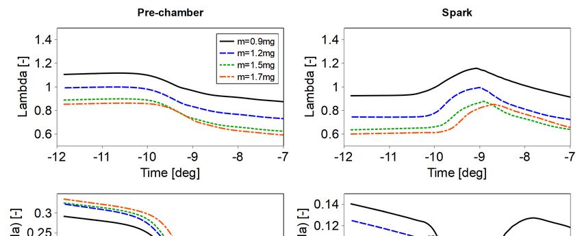
3.1 Advanced Ignition Modelling for Pre-chamber Combustion in Lean Burn Gas Engines

 Figure 3: Velocity, turbulent velocity, inverse equivalence ratio and turbulent length-
 scale near spark plug gap for m=0.9mg injection, at -11.15deg

 Figure 4: Pre-chamber and spark region mixture composition

Figure 4 illustrates the composition of mixture and its homogeneity in terms of the av-
erage values of λ within the pre-chamber and the spark volumes. As could be ex-
pected, an increase in the injection mass leads to an increase in the equivalence ratio
in both control volumes. Longer injection timings increase inhomogeneity levels in the
pre-chamber. However, the effect on the spark volume is opposite. The results indicate
that when controlling the total injected mass, it is beneficial to target values slightly
leaner (~10% in the investigated case) than estimated stoichiometry based on the pre-
chamber volume and density.

114
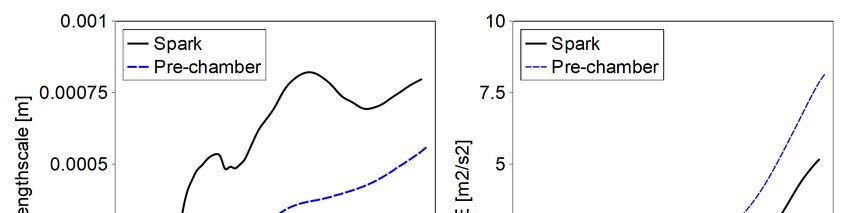
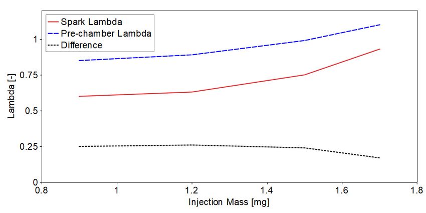
3.1 Advanced Ignition Modelling for Pre-chamber Combustion in Lean Burn Gas Engines

An interesting observation is that while the spark volume is always richer than the pre-
chamber on average, the actual difference of the average λ between the two volumes
at the point of ignition does not change significantly with the injected mass (Figure 5).

 Figure 5: Pre-chamber and spark region mixture composition at ignition point

The integral length scale and turbulence levels at the spark location and in the pre-
chamber up to the ignition time are illustrated in Figure 6 for a representative injection
case with baseline model parameters. The spark region is less turbulent due to the
sheltering by the spark body. The actual integral length-scale is lower than the a-priori
estimation.

 Figure 6: Integral lengthscale evolution (injected mass m=0.9mg, injection timing: -
 74.3- -56.3deg)

Figure 7 shows the evolution of the kernel radius, critical parameters and the kernel
temperature. As the kernel grows, the turbulent component of the flame speed be-
comes much greater than the laminar component and the turbulent flame brush thick-
ness l and the critical radius become identical. The kernel radius for this case
grows much faster than the flame brush thickness and as a result, no quenching is

 115
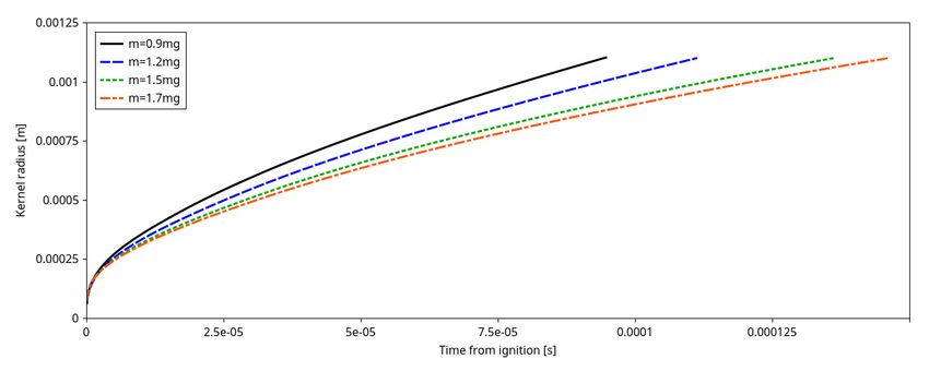
3.1 Advanced Ignition Modelling for Pre-chamber Combustion in Lean Burn Gas Engines

observed. The temperature relaxes over the first ~20µs and becomes close to the ad-
iabatic flame temperature, which is in line with the behavior reported in other studies
(e.g. [11]).
The kernel radius at this point is ~0.5mm, which is the appropriate initial kernel radius
for models neglecting the evolution of the kernel temperature. The final critical radius,
based on the flame front thickening , is much smaller than the critical radius based
on the turbulent length scale of the external turbulence , illustrated in Figures 3 and
6, indicating that the limiting factor for the quenching is the external turbulent field, and
not the turbulence generated by the flame front.

 Figure 7: Kernel evolution for the baseline model parameters, (injected mass
 m=0.9mg)

The speed of the flame kernel growth follows the composition of the mixture in the
spark region as shown in Figure 8.

 Figure 8: Kernel evolution for the baseline model parameters, (injected mass
 m=0.9mg)

The flame jet exit time obtained in the simulations and the comparison with the exper-
imental data are summarized in Table 6. The jet exit times were determined in the

116
3.1 Advanced Ignition Modelling for Pre-chamber Combustion in Lean Burn Gas Engines

simulation by calculating the time at which the concentration of the burnt fuel in the
mass flow rate through the outlets of pre-chamber nozzles reaches 4.5%.
The time was then averaged between the nozzles. Tests with various thresholds
showed low sensitivity to the threshold value (see [13] for more detail). Experimental
jet exit times are determined by the threshold in OH* chemiluminescence levels. It is
difficult to compare the two levels directly. However, the indication of the agreement is
the offset between the two values, which is constant apart from the outlier 1.5mg in-
jection, which also shows a local maximum in the standard deviation of the experi-
mental results.

 Table 6: Flame jet exit timings for baseline set-up

 Injected Experiment Simulation
 mass Flame jet exit Standard devi- Flame jet exit Difference vs
 (mg) time ation time experiment
 (ms) (%) (ms) (%)
 0.9 0.75 11.3 0.58 22.6
 1.2 0.81 12.5 0.60 23.5
 1.5 0.94 15.5 0.66 30.0
 1.7 0.88 9.8 0.68 22.7

The results reported in Table 6 show higher deviation from the experimental data than
the results reported in [22], where a different experimental set-up was considered with
a much shorter injection duration. Note that results reported in [22] were obtained with
the effective spark power of 180W and transition radius of 4mm, in effect delaying the
flame development.

Simulation of cases with varying number of particles demonstrated that the flame jet
exit times exhibit no sensitivity to kernel. For example, the variation of the maximum
of recorded flame jet exit time between the nozzles, when changing the number density
from 20000 to 1000 particles was equal to 0.06% for the baseline case with 0.9 injected
mass. The critical gas phase Courant number for the initial stage of the kernel growth
comprising the first ~20µs during which the temperature relaxes to adiabatic flame
temperature was found to be equal to 0.1. While the model would still converge, in-
creasing time step beyond this value resulted in a sharp unphysical decrease of the
kernel temperature. After this initial stage, the model was found to be stable with the
gas phase Courant number of up to 2.

The increase in the breakdown energy leads to the increase in the initial flame kernel
size, which results in faster cooling of the kernel due to a higher initial surface area.
The current implementation of the model explicitly restricts the contraction of the ker-
nel, hence this slower initial growth still leads to the same values of the kernel radius
at later times (Figure 9).

 117
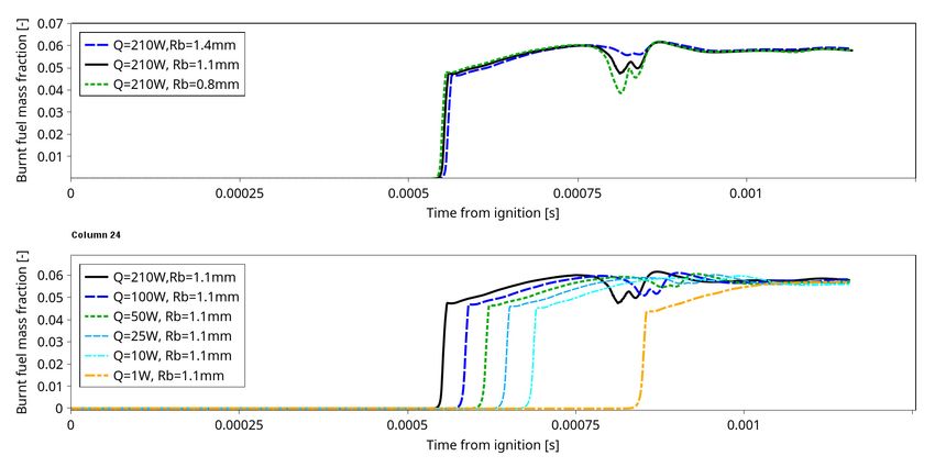
3.1 Advanced Ignition Modelling for Pre-chamber Combustion in Lean Burn Gas Engines

 Figure 9: Effect of the breakdown energy on the kernel growth (injected mass
 m=0.9mg)

Within the 1D model context, increase of the transition radius is equivalent to an ex-
tension of the duration of the 1D stage. Extended duration of the 1D model slows down
the development of the flame and increases the flame jet exit time. The decrease of
the effective power has the same effect; hence it is useful to consider the two together.
Figure 10 shows the burned fuel mass fraction in the mass flow rate through one of
pre-chamber nozzles (there was no substantial asymmetry observed between the noz-
zles). The variation of the transition radius for the same spark within the limits sug-
gested in [10] does not have a strong effect on the flame jet exit time. However, the
effective spark power change within the 210W-1W range changes the jet exit time by
0.31ms (1.1deg).

 Figure 10: Effect of the effective power and transition radius on flame propagation
 (injected mass m=0.9mg)

118
3.1 Advanced Ignition Modelling for Pre-chamber Combustion in Lean Burn Gas Engines

The effective spark power in the range 180-210W, has been shown to produce correct
results when compared with the experiments of Maly [15] ([5, 13]), with a different coil.
The same set-up also showed good results when compared with the measurements
done in the optical engine for a similar coil/spark combination [5]. While some variation
in the effective power depending on ambient pressure, density and spark coil proper-
ties can be expected, the values of the effective power ~5W required to close the gap
with the experimentally observed flame jet exit times are not realistic.

5 Conclusions
The Dynamic Discrete Particle Ignition Kernel has been designed and implemented
within the VECTIS software product as part of the Horizon 2020 GasOn project. This
model has been successfully validated against academic test cases in other published
works and here the model is used within a Rapid Expansion Compression Machine
environment.

The results have shown that there can be some variation between simulation results
and those from measurements when comparing the time taken for an ignition event to
travel from the spark through the pre-chamber and into the main combustion chamber.
The implemented ignition model has several input parameters which are subject to
uncertainty. Here these parameters have been investigated to examine the effect that
they have on this discrepancy between the flame jet timings.

The sensitivity to the number of particles used in the DDPIK model is slight, with a
reduction from 20000 to 1000 producing only a 0.06% change in the results. The re-
duction in the number of particles being tracked also results in a reduction in compu-
tational cost, improving the model for industrial applications and time frames. Variation
of the transition timing for the same spark energy also produces small variations and
does not produce as strong effect on the flame jet exit timing. The results are sensitive
to the effective spark power input parameter. However the variation of the effective
spark power input within reasonable limits does not allow closing the gap with the ex-
perimentally observed flame jet timings.

The dynamic discrete particle ignition model shows good robustness and accuracy
over a range of air-fuel ratios. The sensitivity analysis of model parameters conducted
here indicates that the uncertainties in the spark model alone cannot account for the
faster flame propagation apparently observed by comparison with the experiment. The
model is robust and can be used with the default settings established in [5.13].

The only remaining factor which can affect the flame jet exit time is the turbulent flame
speed closure used in the G-equation part of the combustion model. In particular, the
value of the coefficient A used in Equation 5 has been reported to be sensitive to flow
conditions and turbulence levels [13, 23, 24].

The effect of the turbulent flame speed on the simulations of the RCEM experiment
are explored in detail in the following publication [13].

 119
3.1 Advanced Ignition Modelling for Pre-chamber Combustion in Lean Burn Gas Engines

Acknowledgements

This work has been supported by the European Union’s Horizon 2020 GASON re-
search and innovation programme under grant agreement No 652816.

Bibliography

[1] Christof Schernus, RD., Knut Habermann, BGP. “Potentials of gas mobility in
 road transport”, BDEW-Fachkongress 2016. Berlin 2016-03-02
[2] Möhring, L., Andersen, J.: “CNG Mobility - Scalable, Affordable and Readily Avail-
 able Solution for Environmental and Climate Challenges” 38. Internationales Wie-
 ner Motorensymposium 2017
[3] Ferrera, M., “Gas-Only Internal Combustion Engines, H2020GV-3-2014 Future
 natural gas powertrains and components for cars and vans”. NGVA – Clean fu-
 ture with g-mobility. Paris. 25 May 2018,
[4] Lucas, G., Tallu, G. and Weißner, M., "CFD-based Development of an Ignition
 Chamber for a lean and highly efficient CNG Combustion", Proc. THIESEL 2018
 Conference on Thermo- and Fluid Dynamic Processes in Direct Injection En-
 gines, 2018.
[5] Tallu, G., Beck, L. M., Prouvier, M., Winkler, A. and Shapiro, E., “3D CFD Model-
 ling and Simulation of Spark Ignition Inclusive of Turbulence Effects and Detailed
 Chemical Kinetics”, Proc. 3rd International Conference on Ignition Systems for
 Gasoline Engines, November 3–4, 2016, Berlin
[6] Tallu G., Frambourg M., Prouvier M., Weißner M., Winkler A., "Numerical Inves-
 tigation of Spark Ignition Processes in Natural Gas Engines with the Advanced
 Spark Ignition Model", Proc. 4th International Conference on Ignition Systems for
 Gasoline Engines, Berlin, December 2018
[7] Sher, E., Ben-YaIsh, J. and Kravchik, T., “On the birth of spark channels”, Com-
 bustion and Flame, 89:168-194, 1992.
[8] Refael S. and Sher E., “A theoretical study of the ignition of a reactive medium
 by means of an electrical discharge”, Combustion and Flame, 59:17-30, 1985.
[9] Rivin B., Dulger M. and Sher E., “Extending Lean Misfire Limit of Methane-Air
 Mixtures by Means of an Enhanced Spark Discharge”, SAE - 1999-01-0573
[10] Tan, Z. and Reitz, R. “Modeling ignition and combustion in spark-ignition engines
 using a level set method”, SAE Technical Paper 2003-01-0722, 2003.
[11] Herweg R. and Maly, R. R. “A fundamental model for flame kernel formation in
 S.I. engines”. In SAE International, 922243, 1992.
[12] Maly R.R., “Spark Ignition, its Physics and Effect on the Internal Combustion Pro-
 cess”, in Fuel Economy: Road Vehicles Powered by Spark Ignition Engines, ed.
 by J.C. Hilliard, G.S. Springer, Plenum Press, New York 91–148 (1984).
[13] Shapiro E., Kyrtatos P., Kotzagianni M., Bolla M., Tiney N., Boulouchos K., "Ex-
 perimental and numerical analysis of pre-chamber combustion systems for lean

120
3.1 Advanced Ignition Modelling for Pre-chamber Combustion in Lean Burn Gas Engines

 burn gas engines", Submitted to SAE World Congress and Exhibition, Manuscript
 no: 19PFL-0579
[14] Bolla M., Shapiro E., Tiney N., Kyrtatos P., Kotzagianni M., Boulouchos K., "Nu-
 merical study of turbulence and fuel-air mixing within a scavenged pre-chamber
 using RANS and LES", Submitted to SAE World Congress and Exhibition, Man-
 uscript no: 19PFL-0664
[15] Maly, R. and Vogel, M., “Initiation and propagation of flame front in lean ch4-air
 mixture by the three modes of the ignition spark”, Proceedings of the 17th Sym-
 posium (international) on Combustion, The Combustion Institute, 17, pp. 821-
 831, 1978.
[16] Maly R.R., Herweg R. “Spark Ignition and Combustion in Four-Stroke Gasoline
 Engines”. In: Arcoumanis C., Kamimoto T. (eds) Flow and Combustion in Recip-
 rocating Engines. Experimental Fluid Mechanics. Springer, Berlin, Heidelberg,
 2008
[17] Miles P. C., RempelEwert B. H., Reitz R. D., “Experimental Assessment of Reyn-
 olds-Averaged Dissipation Modeling in Engine Flows”, SAE-2007-24-0046
[18] Lipatnikov, A.N. and Chomiak, J. "Turbulent Flame Speed and Thickness: Phe-
 nomenology, Evaluation, and Application in Multi-Dimensional Simulations", Pro-
 gress in Energy and Combustion Science, 28, No. 1, pp. 1-73, 2002
[19] Ewald, J. and Peters, N., “On unsteady premixed turbulent burning velocity pre-
 diction in internal combustion engines.”, Proceedings of the Combustion Institute,
 31:3051–3058, 2007.
[20] Stiesch G, Merker GP, “A Simplified Model for Description of Triple Flames in
 Stratified Charge Gasoline Engines”, in: Proc 12th Int. Multidim. Engine Modeling,
 Users Group Meeting, Detroit, MI, 2002.
[21] Przulj, V., Tiney, N., Shapiro, E., Penning, R. and Shala, M., “The time scale
 bounded k-e turbulence model and its assessment for automotive applications”,
 Proc. 7th Int. Symp. Turbulence, Heat and Mass Transfer, Palermo, Italy, 2012
[22] Hernández, I., Shapiro, E., Tiney, N., Kotzagianni, M., Kyrtatos, P. and Bou-
 louchos, K., “Flame-wall interaction modelling for pre-chamber combustion in
 lean burn gas engines”, Proceedings of 34th International CAE Conference and
 Exhibition, 2018, Vicenza, Italy
[23] Schmitt M., Hu, R., Wright, Y. M., Soltic P. and Boulouchos K. “Multiple Cycle
 LES Simulations of a Direct Injection Methane Engine,” Flow, Turbulence and
 Combustion (95):645–668, 2015
[24] Xu, G., Hanauer, C., Wright, Y., and Boulouchos, K., "CFD-Simulation of Ignition
 and Combustion in Lean Burn Gas Engines", SAE Technical Paper 2016-01-
 0800, 2016, doi:10.4271/2016-01-0800
[25] Kammermann T., Kreutner W., Trottmann M., Merotto L., Soltic P., Bleinera D.,
 "Spark-induced breakdown spectroscopy of methane/air and hydrogenenriched
 methane/air mixtures at engine relevant conditions", Spectrochimica Acta Part B
 148, pp. 52–164, 2018

 121
You can also read